
As an automotive technician specializing in hybrid electric vehicles, I recently encountered a challenging case involving a 2016 Hyundai Sonata hybrid electric vehicle. This incident highlights the critical importance of insulation integrity in high-voltage systems of hybrid electric vehicles. In this article, I will detail the diagnostic process, technical insights, and preventive measures, emphasizing the complexities of modern hybrid electric vehicle architectures. The goal is to provide a comprehensive resource for professionals dealing with similar issues in hybrid electric vehicles.
The customer reported an intermittent stalling issue during driving, followed by an inability to enter READY mode. This symptom is particularly concerning in a hybrid electric vehicle, as it directly impacts the vehicle’s ability to utilize its electric propulsion system. Upon initial inspection, I confirmed the fault: the vehicle would occasionally shut down unexpectedly, and the READY indicator failed to illuminate, indicating a disruption in the high-voltage system activation sequence. Such problems in a hybrid electric vehicle often point to underlying issues with the battery management system (BMS) or related components.
To begin the diagnosis, I connected a professional fault diagnostic scanner to the vehicle’s OBD-II port. The scanner retrieved a historical fault code from the Battery Management System (BMS): “POAA6 – Battery High Voltage System Insulation Deterioration.” This code is pivotal in hybrid electric vehicles, as it signals that the insulation resistance between the high-voltage circuit and the vehicle chassis has fallen below a safe threshold. The BMS in a hybrid electric vehicle continuously monitors this resistance to prevent electrical hazards, such as short circuits or leakage currents, which could compromise safety and performance. However, the BMS only flags the anomaly without specifying the exact location of the fault, necessitating a systematic investigative approach.
Insulation resistance is a fundamental parameter in any electrical system, especially in hybrid electric vehicles where voltages can exceed 300V DC. The resistance \( R_{ins} \) is defined by Ohm’s law applied to insulation: $$ R_{ins} = \frac{V}{I_{leak}} $$ where \( V \) is the system voltage and \( I_{leak} \) is the leakage current. For hybrid electric vehicles, manufacturers typically set a minimum threshold; in this case, the BMS triggers a fault when \( R_{ins} \) drops below 300 kΩ. This ensures that leakage currents remain within safe limits, preventing potential shocks or fire risks. The degradation of insulation can result from factors like moisture ingress, physical damage, component aging, or contamination—common challenges in the operational lifespan of a hybrid electric vehicle.
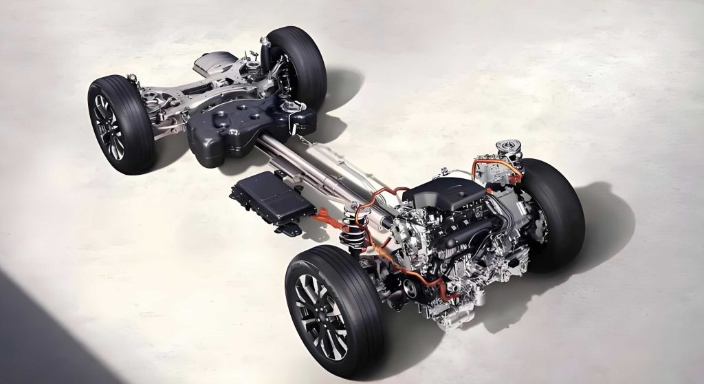
The high-voltage system in this hybrid electric vehicle comprises several key components, as outlined in the table below. Understanding this architecture is essential for effective troubleshooting.
| Component | Function | Typical Voltage Range |
|---|---|---|
| High-Voltage Battery Pack | Stores electrical energy for propulsion | 200-400V DC |
| Power Relay Assembly (PRA) | Controls high-voltage circuit engagement | System Voltage |
| Hybrid Power Inverter | Converts DC to AC for motor drive | System Voltage |
| Traction Motor | Provides propulsion torque | AC Variable |
| Starter-Generator | Assists engine start and regeneration | AC Variable |
| Electric Oil Pump | Lubricates transmission components | System Voltage |
| Electric A/C Compressor | Provides cabin cooling | System Voltage |
| High-Voltage Cabling | Interconnects all components | System Voltage |
Given the fault code, I hypothesized that the insulation failure could originate from any of these components or their associated wiring. In hybrid electric vehicles, insulation faults are often intermittent initially, making them elusive to diagnose. My first step was a visual and physical inspection of all high-voltage connectors and harnesses. I checked for signs of corrosion, deformation, contamination, or damage—common culprits in electrical systems of hybrid electric vehicles. However, no obvious anomalies were found, prompting a more in-depth electrical testing procedure.
To safely measure insulation resistance, I followed standard protocols for hybrid electric vehicles: turning off the ignition, disconnecting the low-voltage battery negative terminal, and using a certified megohmmeter (insulation resistance tester). The measurement points were selected at the Power Relay Assembly (PRA), which acts as a central hub for the high-voltage distribution. Referring to the vehicle’s wiring diagrams, I disconnected the high-voltage connector between the PRA and the hybrid inverter. Using the megohmmeter, I measured the resistance between each high-voltage terminal (B03-IP/1 and B03-IN/1) and the vehicle chassis ground. The results were consistent and alarming: both measurements showed approximately 150 kΩ, well below the 300 kΩ threshold. This confirmed an insulation fault in the hybrid electric vehicle’s high-voltage system.
The next challenge was isolating the faulty component. In hybrid electric vehicles, the high-voltage system is a parallel network, meaning that a single faulty component can drag down the overall insulation resistance. I employed a divide-and-conquer strategy by sequentially disconnecting each high-voltage component while monitoring the insulation resistance at the PRA. The process can be modeled using the formula for parallel resistances: $$ \frac{1}{R_{total}} = \frac{1}{R_1} + \frac{1}{R_2} + \cdots + \frac{1}{R_n} $$ where \( R_{total} \) is the overall insulation resistance measured, and \( R_1, R_2, \ldots, R_n \) represent the insulation resistances of individual components or branches. By disconnecting one component at a time, I effectively removed its contribution from the parallel network, allowing me to identify the culprit.
| Component Disconnected | Measured Insulation Resistance (PRA to Ground) | Inference |
|---|---|---|
| None (initial) | 150 kΩ | Fault present in system |
| Hybrid Inverter | 180 kΩ | Improvement but still faulty |
| Traction Motor | 200 kΩ | Improvement but still faulty |
| Starter-Generator | 220 kΩ | Improvement but still faulty |
| Electric Oil Pump | 250 kΩ | Improvement but still faulty |
| Electric A/C Compressor | >300 kΩ | Resistance normalizes, fault isolated |
As shown in the table, when I disconnected the electric A/C compressor’s high-voltage connector (C107-P), the insulation resistance immediately rose above 300 kΩ, indicating that this component was the source of the leakage. To further verify, I directly measured the insulation resistance at the compressor terminals. Using the megohmmeter, I tested between terminal C107-P/1 and ground, and between C107-P/2 and ground. Both readings were around 150 kΩ, confirming that the compressor itself had internal insulation breakdown. This is a critical finding, as the A/C compressor in a hybrid electric vehicle operates at high voltages and is susceptible to moisture accumulation or internal winding faults over time.
The physics behind insulation degradation in hybrid electric vehicle components often involves factors like dielectric strength loss. The dielectric strength \( E \) of an insulating material is given by: $$ E = \frac{V_{breakdown}}{d} $$ where \( V_{breakdown} \) is the voltage at which insulation fails, and \( d \) is the thickness of the insulation. In the A/C compressor, prolonged thermal cycling and vibrational stresses could have reduced \( d \) or compromised the material, lowering \( E \) and allowing leakage currents to flow. This leakage current \( I_{leak} \) can be estimated using: $$ I_{leak} = \frac{V}{R_{ins}} $$ For a system voltage of 300V and \( R_{ins} = 150 \text{ kΩ} \), \( I_{leak} \approx 2 \text{ mA} \), which, while small, exceeds the BMS threshold and can trigger protective shutdowns in a hybrid electric vehicle.
Replacing the faulty electric A/C compressor resolved the issue. After installation, I performed a comprehensive insulation resistance test on the entire high-voltage system, ensuring all values exceeded 300 kΩ. A road test confirmed that the hybrid electric vehicle no longer stalled and could consistently enter READY mode. This case underscores the importance of systematic diagnostics in hybrid electric vehicles, where insulation faults can mimic other issues. Preventive maintenance for hybrid electric vehicles should include periodic insulation checks, especially before seasonal changes when humidity fluctuations can exacerbate latent faults.
In conclusion, insulation integrity is paramount for the safety and reliability of hybrid electric vehicles. The diagnostic process highlights the need for specialized tools and knowledge when working on high-voltage systems in hybrid electric vehicles. By understanding the electrical principles and employing methodical testing, technicians can efficiently locate and resolve such faults. As hybrid electric vehicles become more prevalent, developing robust diagnostic protocols will be essential for maintaining their performance and ensuring user safety. Future advancements in hybrid electric vehicle technology may incorporate real-time insulation monitoring at the component level, further enhancing fault detection capabilities.
To generalize, the insulation resistance \( R_{ins} \) in a hybrid electric vehicle should ideally be infinite, but practical thresholds are set based on safety standards. The time-dependent degradation of insulation can be modeled with an exponential decay function: $$ R_{ins}(t) = R_0 \cdot e^{-\lambda t} $$ where \( R_0 \) is the initial resistance, \( \lambda \) is a degradation constant dependent on environmental factors, and \( t \) is time. Regular monitoring can help predict failures before they cause operational disruptions in hybrid electric vehicles.
For technicians, I recommend maintaining detailed records of insulation measurements for each hybrid electric vehicle serviced. This data can reveal trends and preemptively identify components at risk. Additionally, always adhere to manufacturer guidelines when servicing high-voltage systems in hybrid electric vehicles, as improper handling can lead to severe injuries or further damage. The integration of advanced diagnostics, such as impedance spectroscopy, could further refine fault localization in future hybrid electric vehicle designs.
Ultimately, this case illustrates how a seemingly erratic symptom in a hybrid electric vehicle—intermittent stalling—traced back to a fundamental electrical fault. Through careful analysis and structured troubleshooting, the issue was resolved, restoring the hybrid electric vehicle to optimal operation. As the automotive industry evolves, the lessons learned from such cases will continue to inform best practices for maintaining and repairing hybrid electric vehicles, ensuring they deliver on their promise of efficiency and sustainability.