
As a technician specializing in modern powertrains, I frequently encounter complex issues in hybrid electric vehicles. The integration of internal combustion engines with electric motors presents unique diagnostic challenges, particularly in emission control systems like the Exhaust Gas Recirculation (EGR) system. In this detailed account, I will share a comprehensive case study involving a persistent EGR flow fault in a plug-in hybrid electric vehicle, expanding on the principles, diagnostic procedures, and lessons learned. The focus will remain on the intricacies of maintaining hybrid electric vehicles, a technology central to the automotive industry’s future.
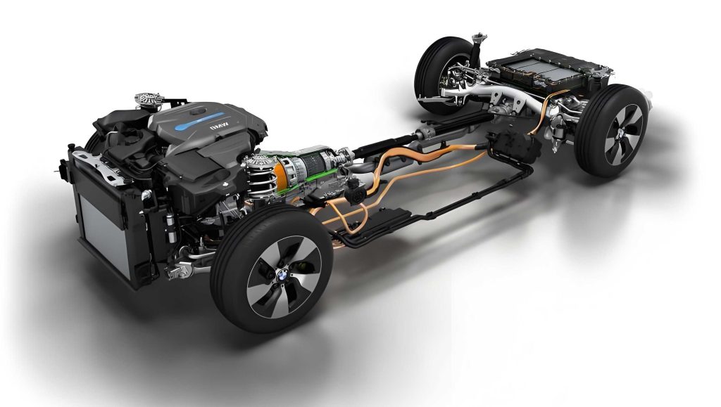
The vehicle in question was a plug-in hybrid electric vehicle, specifically a 2018 model with a cumulative mileage of 28,000 km. This hybrid electric vehicle combined a 2.0L naturally aspirated gasoline direct injection engine with a 50 kW permanent magnet synchronous electric motor, mated to a 6-speed automatic transmission. It offered a pure electric range of 75 km. The owner reported that during driving, when the vehicle switched from EV (Electric Vehicle) mode to PHEV (Plug-in Hybrid Electric Vehicle) mode, the engine malfunction indicator lamp (MIL) on the instrument cluster illuminated abruptly. Despite this warning, the hybrid electric vehicle continued to operate normally, which is a common but misleading characteristic in many hybrid electric vehicle fault scenarios.
Upon initial inspection, I connected a professional-grade diagnostic scan tool to the vehicle’s onboard diagnostic port. The system revealed a single stored fault code within the engine control module: P040100. This code’s definition was “EGR ‘A’ Flow Insufficient Detected.” In the context of a hybrid electric vehicle, where the engine operates intermittently, such fault codes can be particularly nuanced. The hybrid electric vehicle’s powertrain control module (PCM) monitors various parameters to ensure optimal efficiency and emissions compliance, especially during transitions between electric and hybrid modes.
To understand this fault, one must first grasp the role of the EGR system in a modern hybrid electric vehicle. The primary function of EGR is to reduce nitrogen oxide (NOx) emissions by recirculating a portion of the engine’s exhaust gas back to the engine cylinders. This dilutes the oxygen concentration in the intake charge and lowers peak combustion temperatures. In a hybrid electric vehicle, the engine often operates under lean-burn or high-efficiency conditions, which can promote NOx formation. Therefore, an effective EGR system is crucial for meeting stringent emission standards. The mass flow rate of EGR can be conceptually described by a simplified equation derived from fluid dynamics principles:
$$ \dot{m}_{EGR} = C_d \cdot A_{valve} \cdot \sqrt{2 \cdot \rho \cdot \Delta P} $$
Where:
$\dot{m}_{EGR}$ is the EGR mass flow rate (kg/s),
$C_d$ is the discharge coefficient of the valve,
$A_{valve}$ is the effective flow area of the EGR valve (m²), which is a function of valve position,
$\rho$ is the density of the exhaust gas (kg/m³),
$\Delta P$ is the pressure differential between the exhaust and intake manifolds (Pa).
The PCM in this hybrid electric vehicle performs a logical test to monitor EGR flow. It commands the EGR valve to open momentarily while observing the response from the Manifold Absolute Pressure (MAP) sensor. The expected increase in MAP is compared against a modeled value based on engine speed and commanded valve position. A discrepancy triggers an internal fault counter, and if exceeded, code P040100 is stored. The possible root causes, as per the service manual, are numerous. I have summarized them in the following table to clarify the diagnostic tree for a technician working on a hybrid electric vehicle.
| Category | Specific Cause | Relevance to Hybrid Electric Vehicle Operation |
|---|---|---|
| Valve & Passage Deposits | Carbon buildup on EGR valve pintle, valve seat, or internal passages | More prone in hybrids due to frequent engine starts/stops and cooler operating temps. |
| System Blockages | Clogged EGR cooler tubes, intake manifold ports, or transfer pipes | Metal debris or severe carbon accumulation can restrict flow. |
| Mechanical Valve Fault | Insufficient valve lift due to wear, sticking, or internal component failure | Directly reduces $A_{valve}$, impacting $\dot{m}_{EGR}$. |
| Air Leaks | Intake manifold leaks downstream of the EGR introduction point | Reduces manifold pressure rise during test, fooling PCM logic. |
| Sensor Issues | Faulty MAP sensor or EGR position sensor providing erroneous data | Can cause false failure detection despite adequate physical flow. |
My first diagnostic step was to analyze the live data stream related to the EGR system. This is a critical phase for any hybrid electric vehicle diagnosis, as parametric data reveals the system’s dynamic behavior. The key parameters monitored included EGR valve commanded position, EGR valve actual position (from its integrated position sensor), MAP sensor reading, engine speed, and a parameter called “EGR actuator signal slope.” The data at idle and during a brief commanded actuation test appeared largely normal, except for a slightly elevated actuator signal slope value. However, in a hybrid electric vehicle, the engine may not be running during initial diagnostics, so forcing the engine into operation via the diagnostic tool is necessary. The MAP readings across different engine speeds were within the specified range, which initially pointed away from a massive intake leak. I present a simplified comparison of observed vs. expected data trends below.
| Parameter | Observed Value | Expected Normal Range | Interpretation |
|---|---|---|---|
| Engine Speed | 750 rpm | 650-850 rpm | Normal |
| Commanded EGR Position | 60% | 0-100% | Test command issued |
| Actual EGR Position | 58.5% | Within ±3% of commanded | Appears normal |
| MAP (Manifold Absolute Pressure) | 48 kPa | ~30-60 kPa at idle | Normal baseline |
| MAP Delta during Valve Test | +3.2 kPa | Expected: +4.0 to +6.0 kPa | Slightly low increase |
| EGR Actuator Signal Slope | 0.85 V/s | Typical: 0.4-0.7 V/s | Elevated, indicating possible mechanical resistance |
The slight deficiency in MAP delta ($\Delta P_{MAP}$) and the elevated slope hinted at a flow restriction or insufficient valve opening. The relationship between the expected MAP increase and EGR flow can be modeled. The PCM likely uses a transfer function similar to:
$$ \Delta P_{expected} = f(N_e, \theta_{EGRcmd}, \dot{m}_{air}) $$
Where $N_e$ is engine speed, $\theta_{EGRcmd}$ is the commanded EGR valve angle or duty cycle, and $\dot{m}_{air}$ is the mass airflow rate. The fault is triggered when:
$$ |\Delta P_{measured} – \Delta P_{expected}| > Threshold $$
for a sustained number of drive cycles. Given the hybrid electric vehicle’s engine operates in transients, this threshold logic is crucial.
Guided by the service manual, I began physical inspections. The intake manifold, especially the plastic sections where the EGR feed tube connects, was examined for cracks or leaks. No issues were found. The hybrid electric vehicle’s engine bay is often tightly packed, making access challenging. I decided to remove the metal transfer pipe connecting the EGR valve assembly to the intake manifold. This allowed visual inspection of the valve’s outlet port and the pipe itself. Both were surprisingly clean, which I attributed to the hybrid electric vehicle’s predominant use in EV mode, resulting in fewer engine running hours and less carbon accumulation. This is a common characteristic of many plug-in hybrid electric vehicles.
Using the bi-directional control function of the scan tool, I activated the EGR valve through its entire range. Visually, the valve stem moved, and the travel seemed adequate, roughly estimated at 5-6 mm. However, a visual estimate is insufficient for precise diagnosis. The valve’s operation seemed smooth, and no obvious binding was felt. I cleaned the visible portions of the valve seat and stem and applied a minimal amount of high-temperature lubricant to ensure free movement. After reassembly, I took the hybrid electric vehicle for an extended road test, forcing it to remain in HEV mode to keep the engine running continuously and trigger the monitoring cycle.
After approximately 80 km of driving, the dreaded MIL illuminated once again. The scan tool confirmed the same code: P040100. This recurrence confirmed an intermittent or subtle mechanical fault that the initial actuation test did not reveal. My subsequent focus shifted to components upstream of the valve. I disconnected the EGR cooler inlet and outlet hoses and used a borescope to inspect the cooler’s internal honeycomb structure. No significant blockage was observed. The pressure drop across a clean EGR cooler can be approximated by the Darcy-Weisbach equation for flow through porous media:
$$ \Delta P_{cooler} = f \cdot \frac{L}{D_h} \cdot \frac{\rho v^2}{2} $$
Where $f$ is the friction factor, $L$ is the flow length, $D_h$ is the hydraulic diameter, and $v$ is the flow velocity. A blocked cooler would cause an excessive $\Delta P_{cooler}$, reducing the available pressure differential ($\Delta P$) for flow through the valve itself. Since the cooler was clear, this parameter was ruled out.
The only remaining major component was the EGR valve assembly itself. I removed it completely from the engine. Upon shaking the valve, I heard a distinct metallic rattling sound from within its housing. This was the critical clue. Carefully disassembling the valve’s motor and gear housing revealed the fault: a small cylindrical bearing that acted as a follower on the valve stem’s cam mechanism had become detached from its shaft. This bearing, with an outer diameter of 8 mm and an inner diameter of 5 mm, was supposed to be pressed onto a 5 mm diameter pin on the valve stem. Its dislocation created excessive lash in the linkage.
To understand the impact, let’s model the valve’s mechanical geometry. The EGR valve converts the rotary motion of a DC motor (common in modern hybrid electric vehicle actuators) into linear pintle movement via a cam and follower mechanism. The theoretical pintle lift ($L_{pintle}$) is a function of the cam rotation angle ($\phi$) and the cam profile radius ($r(\phi)$):
$$ L_{pintle}(\phi) = r(\phi) – r_{base} $$
When the follower bearing is correctly installed, the effective contact point ensures the designed lift profile. If the bearing is dislodged, the contact point shifts, introducing a positional error ($\delta$). The actual lift becomes:
$$ L_{actual}(\phi) = L_{pintle}(\phi) – \delta $$
In this case, $\delta$ was approximately 1.5 mm. This directly reduced the effective flow area $A_{valve}$ at any given commanded position. The flow area is often proportional to the lift for a poppet-style valve:
$$ A_{valve} \approx \pi \cdot d_{seat} \cdot L_{actual} \cdot \sin(\alpha) $$
Where $d_{seat}$ is the seat diameter and $\alpha$ is the valve seat angle. A reduction in $L_{actual}$ by 1.5 mm caused a significant, though not total, reduction in $A_{valve}$. This explained why the flow was insufficient to meet the PCM’s expected MAP increase during its functional test, but not so low as to cause immediate drivability issues in this hybrid electric vehicle. The fault counter incremented over several drive cycles until the threshold was crossed. The following table summarizes the effect of the mechanical fault on the system parameters.
| Parameter | Design Value | Fault Condition Value | Impact on Flow Equation |
|---|---|---|---|
| Valve Pintle Lift ($L$) | 6.0 mm (max approx.) | 4.5 mm (max approx.) | Reduced by 25% |
| Effective Flow Area ($A_{valve}$) | $A_{design}$ | ~0.75 $A_{design}$ (estimated) | Direct multiplier in $\dot{m}_{EGR}$ |
| Mass Flow Rate ($\dot{m}_{EGR}$) | $\dot{m}_{required}$ | ~0.75 $\dot{m}_{required}$ (estimated) | Insufficient to meet PCM model |
| MAP Increase ($\Delta P_{MAP}$) | $\Delta P_{expected}$ | ~0.7-0.8 $\Delta P_{expected}$ | Triggers fault code when error > threshold |
The repair was straightforward but required attention to detail. I reinstalled the loose bearing onto its pin. Noting the absence of any axial retention clip or press-fit interference, I applied a small amount of high-temperature, thread-locking adhesive to the bearing’s inner race to secure it to the pin, preventing future detachment. After reassembling the valve and reinstalling it on the engine, I cleared the fault code and performed another extended road test. The hybrid electric vehicle was driven over 150 km in various modes, including aggressive acceleration to load the engine and numerous EV/PHEV transitions. The MIL remained off, and subsequent scans showed no pending codes. Since the vehicle was still under warranty, a complete new EGR valve assembly was later ordered and installed as a final remedy, but my repair had confirmed the diagnosis conclusively.
Reflecting on this diagnostic journey, the key takeaway for any technician working on hybrid electric vehicles is the importance of methodical verification. My initial oversight was relying on a simple actuation test and visual lift estimation. In a hybrid electric vehicle, where the engine’s run time is fragmented, fault manifestation can be gradual. I should have quantitatively measured the valve’s lift using a dial indicator during the actuation test, comparing it against specification. The service manual procedure explicitly called for measuring valve lift after removal if flow issues were suspected. Bypassing this step led to unnecessary disassembly of other components. The mathematical relationship between lift and flow area is fundamental; assuming “looks okay” is insufficient. Furthermore, the hybrid electric vehicle’s unique operating pattern—long periods of electric driving—can mask issues that only appear after sustained engine operation, making extended testing in HEV mode essential.
In conclusion, diagnosing emission control systems in a hybrid electric vehicle requires a deep understanding of both traditional internal combustion engine principles and the specific control strategies of hybrid powertrains. The EGR system, critical for NOx reduction, relies on precise mechanical operation and accurate sensor feedback. Faults like P040100, which indicate flow insufficiency, demand a structured approach: verifying sensor data, modeling expected system behavior, and performing definitive physical measurements before component replacement. This case underscores that even in advanced hybrid electric vehicles, basic mechanical failures like a dislodged bearing can cause sophisticated electronic fault codes. As the fleet of hybrid electric vehicles continues to grow, technicians must adapt their diagnostic skills to integrate data analysis with rigorous mechanical verification, ensuring these complex vehicles remain efficient, clean, and reliable.