
The evolution of the automotive industry is unequivocally steering towards electrification, with hybrid electric vehicles (HEVs) serving as a pivotal transitional technology. The core of a hybrid car’s powertrain is its electromechanical coupling system (EMCS), a sophisticated assembly that seamlessly integrates an internal combustion engine (ICE) with one or more electric motors and a gear transmission system. The overall drivetrain efficiency of a hybrid car is fundamentally dictated by the performance of this EMCS. Even minor improvements in its transmission efficiency can translate into significant gains in fuel economy and extended electric driving range. This analysis delves into the primary factors influencing the efficiency of a hybrid car’s EMCS, presenting a detailed examination of power loss mechanisms, experimental methodologies for their quantification, and actionable strategies for optimization.
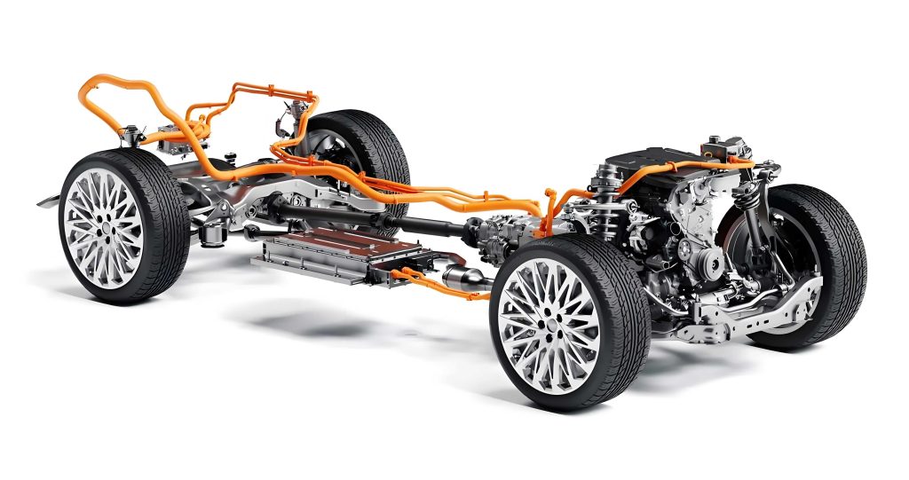
The electromechanical coupling system in a modern hybrid car is a masterpiece of engineering integration. Unlike a conventional transmission, it incorporates electric motors and their power electronics directly into the gearbox housing. A typical configuration, which forms the basis of this study, includes two electric machines—a generator (EM1) and a traction motor (EM2)—multiple clutches and brakes, a planetary gear set or parallel-shaft gears for power-split or parallel hybrid functionality, and a differential. This design enables multiple operating modes such as pure electric drive, series hybrid, engine direct drive, parallel drive, and regenerative braking. The dynamic switching between these modes allows the hybrid car to exploit the high-efficiency regions of the ICE while supplementing with electric power for performance, thereby optimizing overall energy usage.
The overall transmission efficiency (\(\eta_{total}\)) of the hybrid car’s EMCS is defined as the ratio of useful mechanical power output at the wheels (or drive shafts) to the total power input, which includes both mechanical input from the ICE and electrical input from the battery. Power loss (\(\Delta P\)) is the antagonist to efficiency. In the context of a hybrid car’s EMCS, these losses can be categorized into three distinct domains: Mechanical Losses, Electronic Control Losses, and Electric Motor Losses.
Analysis of Power Loss Mechanisms
1. Mechanical Power Losses
Mechanical losses are inherent to any geared transmission and arise primarily from frictional interactions. For a hybrid car, these losses are concentrated in gear meshing and bearing rotation. Although the EMCS structure for a hybrid car may be complex, the fundamental physics of these losses remain.
Gear Meshing Loss (\(P_{v1}\)): This load-dependent loss occurs at the contacting tooth surfaces of mating gears. It is a function of transmitted torque, sliding velocity, and the coefficient of friction. A widely accepted model for this power loss is given by:
$$P_{v1} = \frac{\mu T_1 n_1 \cos^2 \beta_\omega}{9549 M}$$
where \(\mu\) is the mesh friction coefficient, \(T_1\) is the pinion torque (N·m), \(n_1\) is the pinion speed (rpm), \(\beta_\omega\) is the helix angle at the pitch circle, and \(M\) is the mesh mechanical efficiency. The friction coefficient \(\mu\) itself is influenced by lubrication conditions, sliding velocity \(v\), and load intensity \(K\):
$$\mu = K^{0.35} L^{0.23} v^{-0.1} \quad \text{and} \quad K = \frac{1000 T_1 (z_1 + z_2)}{2 b_w r_{\omega2} \omega_1 z_2}$$
Here, \(L\) is a lubricant constant, \(z\) denotes tooth numbers, \(b_w\) is face width, and \(r_\omega\) is pitch radius.
Bearing Friction Loss (\(P_{v2}\)): Rolling element bearings support all rotating shafts in the hybrid car’s EMCS. Their power loss is primarily due to viscous friction of the lubricant and elastic hysteresis. The total frictional torque (\(M_{bear}\)) can be modeled as:
$$P_{v2} = \frac{(M_1 + M_2) n}{9549}$$
where \(M_1\) is the load-dependent torque and \(M_2\) is the speed-dependent (viscous) torque. Simplified models often express these as:
$$M_1 = f_1 (P_1)^{a} d_m^{b}, \quad M_2 = 10^{-7} f_2 (\nu n)^{2/3} d_m^{3} \text{ (if } \nu n \geq 2000\text{)}$$
Here, \(f_1, f_2\) are factors depending on bearing design and load, \(P_1\) is the dynamic equivalent load, \(d_m\) is the mean bearing diameter, and \(\nu\) is the kinematic viscosity of the lubricant.
These formulas highlight that mechanical losses in a hybrid car’s gearbox are strongly influenced by rotational speed (affecting sliding velocity and viscous drag) and lubricant properties (viscosity).
2. Electronic Control Unit (ECU) Power Losses
The ECU, or inverter, is the brain of the electric drive in a hybrid car. It converts direct current (DC) from the battery into alternating current (AC) for the motors (and vice-versa during regeneration) using semiconductor switches, typically Insulated-Gate Bipolar Transistors (IGBTs) and anti-parallel Free-Wheeling Diodes (FWDs). Losses here are purely electrical and manifest as heat.
IGBT and FWD Losses (\(P_{IT}, P_{FT}\)): The total loss in each switching device comprises conduction loss and switching loss.
$$P_{IT} = P_{I,cond}(T_{Ij}, i_a(t)) + P_{I,sw}(V_{dc}, T_{Ij}, i_a(t), r_g, f_{sw})$$
$$P_{FT} = P_{F,cond}(T_{Fj}, i_a(t)) + P_{F,sw}(V_{dc}, T_{Fj}, i_a(t), r_g, f_{sw})$$
- Conduction Loss: Proportional to the on-state voltage drop and the current. It dominates at high torque (high current) conditions.
- Switching Loss: Occurs during the finite time of turning the device on and off. This loss is proportional to the switching frequency (\(f_{sw}\)), the DC-link voltage (\(V_{dc}\)), and the current. It is a critical loss mechanism, especially at partial load and high speed.
Therefore, the ECU loss in a hybrid car is highly dependent on the switching frequency strategy and the operating point (current, voltage) of the motor.
3. Electric Motor Power Losses
The electric motors (EM1 and EM2) in a hybrid car are permanent magnet synchronous machines (PMSMs). Their losses consist of copper losses and iron core losses.
Copper Losses (\(P_{Cu}\)): These are Joule heating losses in the stator windings due to electrical resistance.
$$P_{Cu} = m I^2 R$$
where \(m\) is the number of phases (typically 3), \(I\) is the RMS phase current, and \(R\) is the phase resistance. Copper loss is directly proportional to the square of the motor current, making it the dominant loss at high-torque, low-speed operation in a hybrid car.
Iron Core Losses (\(P_{Fe}\)): These occur in the laminated steel stator and rotor cores due to alternating magnetization. They are commonly separated into hysteresis, eddy current, and excess (or anomalous) losses.
$$P_{Fe} = P_h + P_e + P_{exc} = K_h f B_m^\alpha + K_e f^2 B_m^2 + K_{exc} f^{1.5} B_m^{1.5}$$
Here, \(f\) is the frequency of the magnetic field (proportional to motor speed), \(B_m\) is the peak flux density, and \(K_h, K_e, K_{exc}\) are material-dependent coefficients. Iron losses increase significantly with motor speed and flux density.
The following table summarizes the key influencing factors for each loss domain in a hybrid car’s EMCS:
| Loss Category | Primary Components | Key Influencing Factors |
|---|---|---|
| Mechanical Loss | Gear meshing, Bearing friction, Churning, Windage | Rotational Speed, Load Torque, Lubricant Viscosity, Friction Coefficients |
| Electronic Control Loss | IGBT conduction/switching, FWD conduction/recovery | Switching Frequency (\(f_{sw}\)), Motor Current, DC-Link Voltage |
| Electric Motor Loss | Copper (Joule) loss, Iron (Core) loss | Motor Current (\(I^2\)), Motor Speed (\(f\)), Magnetic Flux Density (\(B_m\)) |
Experimental Methodology for Efficiency Mapping
To validate the theoretical analysis and quantify the impact of each loss component, a dedicated test bench for the hybrid car’s EMCS was developed. The bench allows for independent control and measurement of mechanical and electrical power flows.
Test Bench Configuration: The setup includes:
- Prime Movers & Absorbers: An input motor simulates the ICE, and two output dynamometers absorb power at the drive shafts.
- Sensors: High-precision speed-torque sensors on input and output shafts. Power analyzers measure voltage and current at both the DC input to the ECU and the AC output to the motor.
- Support Systems: A battery simulator provides stable high-voltage DC power. A thermal management system controls the oil temperature of the EMCS. A central controller coordinates all components.
Testing Procedure & Data Reduction: For a given operating mode (e.g., pure electric drive), the test procedure is:
- Set the output dynamometers to the target vehicle speed (converted to EM2 speed).
- Command the ECU to apply the target motor torque.
- Record steady-state data: Shaft speeds/torques, DC power (\(P_{DC}\)), AC power (\(P_{AC}\)), and output mechanical power (\(P_{out}\)).
The losses are then derived as follows:
$$P_{Total Loss} = P_{in} – P_{out} \quad \text{(where } P_{in} = P_{DC} \text{ in pure EV mode)}$$
$$P_{ECU Loss} = P_{DC} – P_{AC}$$
$$P_{Motor Loss} = P_{AC} – P_{out}$$
$$P_{Mech Loss} = P_{Total Loss} – (P_{ECU Loss} + P_{Motor Loss})$$
The pure electric drive mode was tested across a comprehensive range to map the efficiency landscape of the hybrid car’s EMCS. The test matrix covered motor speeds from 500 to 11,000 rpm and torques from 10 to 250 N·m.
Results, Discussion, and Optimization Strategies
The experimental results revealed distinct efficiency characteristics and loss distributions, providing clear directives for optimization.
Efficiency Map and Loss Distribution
The overall system efficiency map showed a peak of 92.5% in the mid-speed, mid-to-high torque region. Notably, a significant low-efficiency zone existed at very low speeds (<1500 rpm) and low torques, where efficiency could drop below 70%. The breakdown of losses provided the explanation:
| Operating Region | Dominant Loss Mechanism | Reason |
|---|---|---|
| Low Speed, Low Torque | Electronic Control (ECU) Loss | High switching-to-conduction loss ratio; fixed switching frequency leads to disproportionate losses at low power. |
| Low Speed, High Torque | Electric Motor (Copper) Loss | High current required for high torque leads to significant \(I^2R\) losses. |
| High Speed, Low Torque | Mechanical Loss | Increased gear/bearing churning and windage losses; load-dependent losses are minimal. |
| High Speed, High Torque | Balanced Mix | All loss components are present but none overwhelmingly dominant, leading to the peak efficiency island. |
Optimization Strategy 1: Reducing Mechanical Loss
Based on the analysis, mechanical loss is highly sensitive to friction conditions. Two targeted improvements were implemented:
- Low-Friction Bearings: Bearings with optimized raceway geometry and special low-drag cages were employed. Bench tests showed a reduction of approximately 30% in frictional torque under typical axial loads.
- Low-Viscosity Lubricant: A specially formulated transmission fluid with lower base oil viscosity (particularly in the 20°C to 90°C range) was used to reduce churning and viscous shear losses.
The combined effect was a measurable uplift in the system’s efficiency map. The peak efficiency increased from 92.5% to 93.4%, and the area of the high-efficiency region (η > 91%) expanded considerably. This demonstrates that even in a highly integrated hybrid car system, traditional mechanical optimization remains highly effective.
Optimization Strategy 2: Dynamic Management of ECU Switching Loss
The tests clearly identified ECU switching loss as the culprit for poor low-load efficiency. A comparative test was conducted between a fixed switching frequency of 10 kHz and 5 kHz. The results were insightful:
- Low-Speed Region (< 4000 rpm): A 5 kHz switching frequency consistently yielded higher system efficiency, with gains exceeding 4 percentage points at very low speed/light load (e.g., 500 rpm, 10 N·m).
- High-Speed Region (> 4000 rpm): The efficiency advantage diminished and sometimes reversed, as a lower switching frequency can increase current ripple and harmonic losses in the motor at higher speeds.
This led to the development of a dynamic switching frequency strategy. Instead of a fixed frequency, the ECU’s \(f_{sw}\) is mapped as a function of motor speed and torque. The core principle is to use a lower frequency (e.g., 5 kHz) in the low-speed, low-torque urban driving zone to minimize switching losses, and a higher frequency (e.g., 10 kHz or above) at higher speeds to maintain good current waveform quality and control bandwidth. Implementing this software-based strategy requires no hardware changes but can significantly improve the real-world driving efficiency of a hybrid car, especially in city traffic.
The following table contrasts the optimization approaches:
| Optimization Target | Method | Key Change | Primary Benefit | Implementation Complexity |
|---|---|---|---|---|
| Mechanical Loss | Hardware Improvement | Low-friction bearings, Low-viscosity oil | Increases peak efficiency & broadens high-efficiency zone. | Medium (Design & fluid change) |
| ECU Switching Loss | Software/Control Strategy | Dynamic \(f_{sw}\) mapping based on operating point. | Dramatically improves low-load efficiency, crucial for city driving. | Low (Software update) |
Conclusion
The pursuit of higher efficiency in hybrid car powertrains necessitates a holistic and detailed understanding of the electromechanical coupling system. This analysis systematically dissected the total power loss into three fundamental streams: mechanical, electronic control, and motor losses. Through theoretical modeling and empirical testing on a bespoke efficiency test bench, the distinct behaviors and dominant regions of each loss component were identified and quantified.
The findings lead to two potent and complementary optimization pathways. First, addressing the classical mechanical losses through advanced low-friction components and tailored lubricants provides a foundational efficiency gain, elevating the peak system capability. Second, and perhaps more critically for the hybrid car’s efficiency in everyday use, is the intelligent management of the power electronics. The implementation of a dynamic switching frequency strategy directly targets the debilitating losses that occur during low-speed, urban driving scenarios, where many hybrid cars operate frequently.
In summary, maximizing the efficiency of a hybrid car’s EMCS is not a singular challenge but a multi-domain one. It requires synergistic improvements in mechanical hardware design, electrical component selection, and, most importantly, intelligent software control that adapts to the driving conditions in real-time. The strategies outlined herein—reducing mechanical friction and dynamically optimizing inverter switching—provide a clear and effective blueprint for engineers to enhance the performance and economy of the next generation of hybrid cars.