
The development of modern vehicles, particularly plug-in hybrid cars, is driven by increasingly stringent global emissions and fuel consumption regulations. As a cornerstone of the new energy vehicle landscape, the plug-in hybrid electric vehicle (PHEV) demands sophisticated control systems to manage the complex interplay between its internal combustion engine and electric drivetrain. The Vehicle Control Unit (VCU), or Hybrid Control Unit (HCU), acts as the central brain of the hybrid car, responsible for critical functions such as torque split between power sources, mode transition, and overall energy management. Developing and validating the control software for this unit directly on a prototype vehicle is highly inefficient. It involves the simultaneous calibration of multiple controllers—the Engine Control Unit (ECU), Transmission Control Unit (TCU), and Motor Control Unit (MCU)—leading to extended development cycles, increased costs, and significant safety risks. Consequently, Hardware-in-the-Loop (HIL) testing has become an indispensable methodology in the automotive industry, enabling rigorous, safe, and repeatable testing of controllers like the HCU in a virtual vehicle environment long before physical prototypes are available.
HIL simulation bridges the gap between pure software simulation and real-world testing. In this setup, the actual electronic control unit (ECU), in this case the HCU, is connected to a real-time simulation platform that mimics the behavior of the vehicle and its environment. The HCU executes its production-intent software, receiving sensor signals and sending actuator commands to the simulation model, which calculates the resulting vehicle dynamics in real-time. This paper details the application of a specific HIL testing platform, centered on MathWorks’ xPC Target solution, for the development and validation of the HCU in a P0P4 architecture plug-in hybrid car. The process encompasses the development of the control strategy model, the configuration of the HIL test bench, the execution of test cases, and the correlation of results with physical vehicle testing.
Powertrain Architecture and Control Model Development
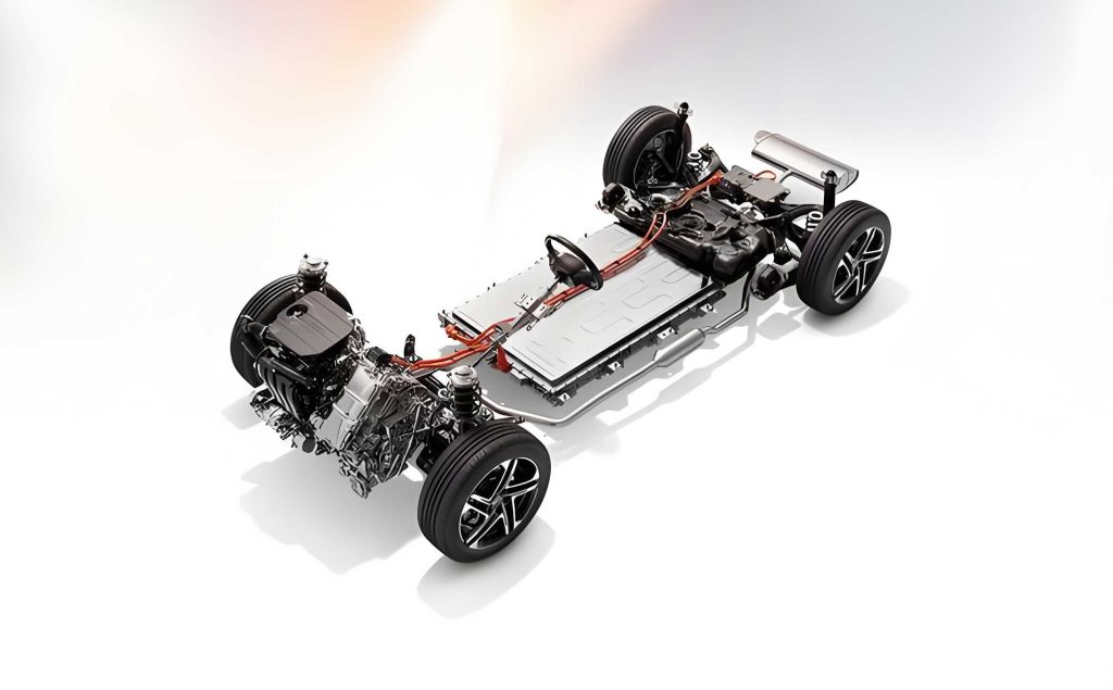
The subject of this development is a plug-in hybrid car utilizing a P0P4 powertrain configuration. This architecture offers a balance of performance, efficiency, and packaging benefits. The front axle is powered by a 1.8-liter turbocharged gasoline engine coupled to a 6-speed Dual-Clutch Transmission (DCT). A Belt-Starter Generator (BSG) motor, connected to the engine via a belt at the P0 position, provides functionalities including engine start-stop, torque assist during certain driving conditions, and limited electricity generation while stationary. The rear axle is driven solely by a permanent magnet synchronous motor (EM) through a fixed-ratio reducer. This rear motor enables pure electric driving, adjusts the engine operating point during hybrid operation, and recovers kinetic energy during braking.
The core of the HCU development is a comprehensive control strategy model built using MATLAB/Simulink. This model defines the logic for managing the complex states of the hybrid car. Its architecture is modular, consisting primarily of input signal processing, a central mode logic and torque coordination module, and output command generation.
The control model’s structure can be summarized in the following functional blocks:
| Module | Primary Function | Key Inputs | Key Outputs |
|---|---|---|---|
| Input Processing | Acquires and conditions signals from hardware I/O and CAN bus. | Accelerator pedal position, brake pedal status, battery state of charge (SoC), vehicle speed, driver mode selection. | Processed signals for downstream modules. |
| Mode Logic & Torque Coordination (Core) | Determines vehicle operating mode and calculates/allocates torque demands. | Processed inputs, current powertrain status. | Identified vehicle mode (EV, HEV, AWD, Engine-only), total torque demand, torque split commands. |
| Output Command Generation | Translates high-level commands into specific actuator signals. | Torque commands, mode flags. | Target torque for Engine, BSG, EM; gear shift commands for DCT; instructions for auxiliaries and dashboard. |
The mode logic module is the intelligence center of the hybrid car’s control system. It follows a sequential decision-making process:
1. Mode Determination: Based on inputs like battery SoC, driver request, and vehicle speed, the current operating mode is selected (e.g., Electric Vehicle (EV) mode, Hybrid Electric Vehicle (HEV) mode, All-Wheel Drive (AWD) mode).
2. Total Torque Demand Calculation: The driver’s request, primarily from the accelerator pedal, is interpreted to calculate the total torque required at the wheels. This calculation considers vehicle speed, gradient, and system limits.
3. Torque Allocation: According to the active mode and an optimized energy management strategy, the total torque demand is split between the engine (front axle) and the EM motor (rear axle). The strategy aims to minimize fuel consumption while meeting drivability constraints. The BSG torque is also determined to either assist, generate, or start the engine.
This logic can be mathematically represented. The total wheel torque demand $T_{wheel}^{req}$ is derived from the driver’s pedal input $\alpha$ and vehicle speed $v$:
$$ T_{wheel}^{req} = f(\alpha, v) $$
This demand is then met by a combination of torques from the internal combustion engine (ICE), the electric motor (EM), and accounting for transmission ratios and losses:
$$ T_{wheel}^{req} \cdot r_{wheel} = (T_{ice} \cdot \eta_{dct} \cdot i_{dct} + T_{bsg} \cdot \eta_{bsg}) \cdot i_{final\_front} + T_{em} \cdot \eta_{em} \cdot i_{final\_rear} $$
where $T_{ice}$, $T_{bsg}$, $T_{em}$ are the torques from the engine, BSG, and EM motor respectively; $\eta$ terms represent efficiencies; $i$ terms represent gear ratios; and $r_{wheel}$ is the wheel radius.
The energy management strategy, crucial for the hybrid car’s efficiency, often uses rules based on battery SoC and power demand. A primary goal is to keep the engine operating in its region of optimal efficiency. The battery SoC dynamics are governed by:
$$ \frac{d(SoC)}{dt} = -\frac{I_{batt}}{Q_{nom}} = -\frac{P_{batt}}{V_{batt} \cdot Q_{nom}} $$
where $P_{batt}$ is the battery power, which is the sum of the power from the EM motor, BSG motor, and accessory loads, considering their efficiencies. The control strategy manipulates $T_{em}$ and $T_{bsg}$ to influence $P_{batt}$ and thus manage the SoC trajectory.
xPC Target Hardware-in-the-Loop Test Platform Configuration
The HIL testing platform is implemented using MathWorks’ xPC Target, a solution designed for rapid prototyping and real-time testing. xPC Target employs a host-target paradigm. The host PC, running a standard operating system like Windows and equipped with MATLAB, Simulink, and Simulink Coder, is used for model development, parameter tuning, and monitoring. The target PC is a dedicated machine that runs a highly optimized, real-time kernel. This kernel executes the compiled vehicle and environment model with deterministic timing, which is critical for accurate HIL simulation.
The role of the xPC system in the context of hybrid car controller testing is to transform the Simulink plant model (vehicle, engine, motors, battery, driver, environment) into real-time code that interacts with the physical HCU through actual I/O interfaces. This creates a closed-loop where the HCU “believes” it is controlling a real hybrid car.
| Component | Role | Specification / Model |
|---|---|---|
| Host PC | Model development, compilation, and monitoring. | OS: Windows; Software: MATLAB/Simulink, RTW, xPC Target, Visual Studio Compiler. |
| Target PC | Real-time execution of the vehicle model. | Industrial PC (e.g., Advantech IPC-610), x86 CPU (e.g., Intel i5), no OS required, boots xPC real-time kernel. |
| I/O Interfaces | Communication between the target PC model and the HCU. | PCI-based CAN interface cards (e.g., Softing CAN-AC2-PCI), Multi-function DAQ card (e.g., NI PCI-6251 for analog/digital I/O). |
| Signal Conditioning | Interface between I/O cards and HCU connectors. | Breakout boxes (e.g., NI SCB-68A) and custom wiring harnesses. |
| Device Under Test (DUT) | The physical Hybrid Car Controller (HCU). | Production-intent or prototype HCU unit. |
The connection and configuration process is systematic. First, the host and target PCs are connected via Ethernet (TCP/IP) for communication. The MATLAB environment on the host is configured to use a C compiler. The xPC Target boot disk is created to load the real-time kernel onto the target PC. Once the target PC boots into the xPC kernel, a connection is established from the host. The Simulink model of the hybrid car, including I/O driver blocks for CAN and analog signals, is then compiled using Real-Time Workshop (RTW) and downloaded to the target PC’s memory. The target PC begins executing the model in real-time, waiting for interaction from the connected HCU.
Controller-in-the-Loop Testing Procedure and Results
With the HIL platform operational, a structured testing procedure is followed to validate the HCU’s software for the plug-in hybrid car.
- Test Definition: Specific test cases are derived from requirements. These include functional tests (mode transitions, torque coordination), diagnostic tests (fault reaction), and performance tests (fuel economy over standard driving cycles like NEDC or WLTP). The inputs (driver actions, road load) and expected outputs are predefined.
- Model Preparation: The appropriate vehicle model is loaded with calibrated parameters (engine fuel maps, motor efficiency maps, battery characteristics, vehicle mass, drag coefficients). The model is first run in a non-real-time simulation on the host to verify basic functionality.
- Model Compilation and Deployment: The verified model is compiled into an executable and downloaded to the target PC. Scopes and data logging blocks are embedded in the model to monitor key signals like vehicle speed, engine torque, motor torque, and battery SoC in real-time on the host PC display.
- Hardware Setup: The physical HCU is connected to the I/O interfaces of the target PC via the conditioning box and harness. Power supplies are connected to the HCU, and its software is flashed with the version to be tested.
- Test Execution and Data Acquisition: The test is initiated from the host PC. The driver model within the simulation follows the target velocity profile of the chosen driving cycle. The HCU responds to the simulated vehicle states by sending torque commands over CAN, which are read by the model. The model calculates the new vehicle state, and the loop continues. All relevant signals are logged throughout the test.
A critical test for any hybrid car is its ability to track a drive cycle. The figure below shows the result of an NEDC cycle test on the HIL platform. The simulated vehicle speed closely follows the target speed profile, demonstrating that the HCU’s torque demand calculation and the virtual powertrain’s response are correctly implemented and provide satisfactory drivability.
Figure: NEDC Cycle Vehicle Speed Tracking on HIL Platform.
[Visual description: A graph with time (s) on the x-axis (0-1200) and speed (km/h) on the y-axis (0-120). Two lines are plotted: a dashed line showing the target NEDC speed profile and a solid line showing the actual simulated vehicle speed. The two lines are nearly indistinguishable, showing excellent tracking.]
Further analysis delves into the torque coordination during hybrid operation. The following chart displays the engine torque command from the HCU versus the actual torque achieved by the engine model during a segment of the NEDC cycle where the engine is active. The close alignment confirms that the engine control logic is functioning as intended within the hybrid system.
Figure: Engine Torque Command vs. Actual in Hybrid Mode.
[Visual description: A graph with time on the x-axis and torque (Nm) on the y-axis. Two lines show the HCU’s target engine torque and the engine model’s output torque. They show strong correlation, with the actual torque closely following the commanded torque with minor dynamic lags.]
Similarly, the performance of the rear electric motor is validated. The plot below illustrates the torque command and response for the EM motor during the same test. The motor accurately provides both positive torque for propulsion and negative torque for regeneration, validating the energy management and braking coordination strategies of the hybrid car controller.
Figure: Electric Motor (EM) Torque Command vs. Actual.
[Visual description: A graph with time on the x-axis and motor torque (Nm) on the y-axis, spanning both positive and negative values. The commanded and actual motor torques are plotted, showing the motor precisely following commands for driving and regenerative braking.]
Correlation with Physical Vehicle Testing
The ultimate validation of any HIL test is its correlation with real-world performance. After successful HIL testing, the HCU software was deployed to a prototype plug-in hybrid car for chassis dynamometer testing under the same driving cycle conditions. The key energy consumption metrics from both the HIL simulation and the physical test were compared.
| Performance Metric | Unit | Real Vehicle Test | HIL Simulation | Relative Error |
|---|---|---|---|---|
| Test Distance | km | 10.94 | 10.94 | 0.0% |
| Engine Energy Output | kWh/100km | 18.67 | 19.00 | +1.8% |
| Average Engine BSFC | g/kWh | 270.95 | 270.79 | -0.1% |
| Fuel Consumption | L/100km | 7.07 | 7.19 | +1.7% |
| Electrical Energy Consumption | kWh/100km | 0.26 | 0.10 | -61.5%* |
*Note: The larger error in electrical consumption is often attributed to differences in accessory load modeling (e.g., power steering, HVAC) between the HIL simulation and the real vehicle test, which can have a proportionally larger impact on the smaller electrical energy value.
The correlation for the primary metric—fuel consumption—is excellent, with an error of only 1.7%. The close match in engine energy output and brake-specific fuel consumption (BSFC) validates the fidelity of the engine model and the effectiveness of the HCU’s energy management strategy in the HIL environment. Discrepancies in secondary metrics like detailed electrical consumption are expected and often stem from simplifications in the auxiliary load models or slight differences in component efficiency maps (static bench data vs. dynamic real-world operation). The overall strong correlation confirms that the HIL test platform provides a sufficiently accurate representation of the hybrid car’s behavior, enabling reliable pre-validation of the HCU software.
Conclusion
The integration of Hardware-in-the-Loop testing, specifically utilizing the xPC Target real-time system, has proven to be a critical and highly effective phase in the development of the整车控制器 for a plug-in hybrid car. This methodology successfully created a virtual proving ground where the complex control strategies for torque split, mode management, and energy optimization could be tested and refined in real-time against a simulated vehicle model. The test results demonstrated that the developed HCU software enabled accurate drive cycle tracking and proper coordination of the hybrid powertrain components. Most importantly, the close correlation between the HIL simulation results and subsequent physical vehicle testing on a chassis dynamometer validates the accuracy and utility of the HIL platform.
The implementation of HIL testing for hybrid car controller development delivers substantial project benefits. It allows for the early detection and resolution of software logic errors and integration issues in a safe, controlled, and repeatable laboratory setting. This significantly reduces the dependency on costly and scarce prototype vehicles during the initial software validation phases, compressing the overall development timeline. Furthermore, it enables comprehensive test coverage, including edge cases and failure modes that would be dangerous or impractical to test on a real vehicle. In conclusion, HIL testing is not merely a supportive tool but a fundamental pillar in the modern, efficient, and robust development process for advanced electrified vehicles like the plug-in hybrid car.