
As an automotive engineer specializing in new energy vehicles, I have witnessed the rapid evolution of hybrid and electric vehicles. The shift from traditional internal combustion engines to electrified powertrains is not just a trend but a necessity driven by the depletion of non-renewable resources, particularly petroleum. In this context, the hybrid car has emerged as a pivotal technology, bridging the gap between conventional and fully electric vehicles. This article delves into the high-voltage battery systems of hybrid cars and electric vehicles, focusing on their architecture, operational principles, and critical maintenance procedures. My aim is to provide a comprehensive guide that emphasizes safety and technical precision, ensuring that technicians and enthusiasts can navigate these complex systems with confidence.
The heart of any hybrid car or electric vehicle lies in its high-voltage electrical system. Unlike traditional vehicles that operate on 12V or 24V DC systems, modern hybrid cars and EVs utilize significantly higher voltages to meet power demands for propulsion. For instance, a typical hybrid car might employ a HV (High-Voltage) battery pack rated at 201.6V, while pure electric vehicles can exceed 400V DC. This voltage escalation is essential for efficient energy conversion and transmission, but it introduces substantial risks during maintenance. Therefore, understanding these systems is paramount. In my experience, the key to safe handling lies in rigorous adherence to protocols, which I will outline in detail.
To begin, let’s explore the core components of a high-voltage system in a hybrid car. These systems are intricately designed to manage energy storage, conversion, and distribution. The primary elements include the traction battery pack, Battery Management System (BMS), charging system, drive motor and DC-DC converter assembly, leakage sensors, high-voltage cables, high-voltage distribution box, and gearshift controllers. Each component plays a vital role in ensuring the hybrid car operates efficiently and safely. Below, I have summarized these components in a table to clarify their functions and interdependencies.
| Component | Function | Typical Specifications |
|---|---|---|
| Traction Battery Pack | Stores electrical energy for propulsion; consists of multiple cells in series/parallel. | Voltage: 201.6V to 800V; Capacity: 1-100 kWh |
| Battery Management System (BMS) | Monitors cell voltage, temperature, and state of charge; ensures balance and safety. | Communication via CAN bus; accuracy: ±0.1% |
| Charging System | Facilitates AC/DC charging from external sources; includes onboard charger. | Power: 3.3 kW to 22 kW; efficiency: >90% |
| Drive Motor & Inverter | Converts DC to AC to drive the motor; regulates torque and speed. | Power: 50-300 kW; voltage input: 200-800V DC |
| Leakage Sensor | Detects insulation faults or current leakage to prevent electric shock. | Threshold: < 100 mA; response time: < 1s |
| High-Voltage Cables | Transmits high-current power between components; insulated for safety. | Cross-section: 25-95 mm²; insulation rating: 600V+ |
| High-Voltage Distribution Box | Distributes power to various subsystems; includes fuses and contactors. | Current rating: 200-400A; IP67 protection |
| Gearshift Controller | Interfaces with transmission to manage power flow in hybrid car modes. | Digital signals; failsafe mechanisms |
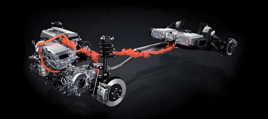
The architecture of a hybrid car’s high-voltage system is often represented through schematic diagrams, which illustrate the flow of energy from the battery to the motor and auxiliary systems. In a typical hybrid car, such as the Toyota LEVIN HYBRID, the HV battery connects via a high-voltage junction box to the inverter, which then powers the motor-generator units. This setup allows for regenerative braking and seamless transition between electric and internal combustion modes. Understanding this layout is crucial for troubleshooting, as any fault in the chain can impact performance. From my perspective, the complexity of these systems necessitates a methodical approach to diagnostics, which I will discuss later.
When it comes to maintenance, the high-voltage nature of a hybrid car demands strict操作规程. I cannot overstate the importance of safety; a single lapse can lead to severe injury or damage. The cornerstone of safe practice is the use of personal protective equipment (PPE). Insulated gloves rated for at least 600V and dielectric shoes are mandatory. Before any work, these must be inspected for integrity—a simple tear can compromise safety. Additionally, all tools should be rated for high-voltage use, and multimeters must have insulated probes. In my routine, I always follow a step-by-step protocol, which I’ve encapsulated in the table below.
| Step | Action | Rationale |
|---|---|---|
| 1 | Park the hybrid car in a well-ventilated area, engage parking brake, and turn ignition to OFF. | Ensures vehicle is stationary and low-voltage systems are de-energized. |
| 2 | Appoint a safety officer to supervise the entire operation. | Provides oversight and ensures compliance with safety norms. |
| 3 | Don PPE: insulated gloves, dielectric shoes, and safety glasses. | Protects against electric shock and arc flashes. |
| 4 | Locate and remove the high-voltage service disconnect (often called the维修开关). | Physically isolates the HV battery from the rest of the system. |
| 5 | Wait at least 10 minutes after disconnection. | Allows capacitors in the inverter and other components to discharge. |
| 6 | Verify zero voltage using a multimeter at designated test points. | Confirms that the system is de-energized before proceeding. |
| 7 | Perform required maintenance or inspection using one-hand rule. | Minimizes risk of current passing through the heart if accidental contact occurs. |
| 8 | After completion, reinstall the service disconnect only after safety officer verification. | Prevents accidental re-energization during reassembly. |
| 9 | Conduct a final check of all connections and insulation. | Ensures integrity before powering up the hybrid car. |
| 10 | Document the procedure and any findings for future reference. | Aids in traceability and continuous improvement. |
The waiting period after disconnecting the high-voltage service disconnect is critical. In a hybrid car, the inverter and DC-DC converter often contain capacitors that store residual energy. The discharge time can be modeled using an RC circuit equation. For a capacitor with capacitance $$C$$ and resistance $$R$$ in the discharge path, the voltage $$V(t)$$ at time $$t$$ is given by:
$$ V(t) = V_0 e^{-\frac{t}{RC}} $$
where $$V_0$$ is the initial voltage. To ensure safety, we wait until $$V(t)$$ falls below a safe threshold, typically 60V DC. For example, if a hybrid car’s system has $$C = 10 \text{ mF}$$ and $$R = 10 \text{ k}\Omega$$, the time constant $$\tau = RC = 100 \text{ s}$$. After $$t = 5\tau = 500 \text{ s}$$ (about 8.3 minutes), the voltage decays to less than 1% of $$V_0$$, justifying the 10-minute rule. This mathematical assurance reinforces the protocol’s importance.
Beyond procedures, several注意事项 must be ingrained in every technician’s mindset. First, always assume the system is live until proven otherwise. Second, never work alone on high-voltage components of a hybrid car; the buddy system is essential for emergency response. Third, keep the removed service disconnect in your pocket to prevent unauthorized reinstallation. Fourth, use insulated tools and avoid wearing metallic jewelry that could cause short circuits. Fifth, be aware of emergency procedures: in case of fire, use dry powder extinguishers or sand, never water-based ones, as water can conduct electricity and exacerbate the situation. I have compiled a concise list of these注意事项 in the table below for quick reference.
| Category | 注意事项 | Reason |
|---|---|---|
| Personal Safety | Wear full PPE; use one-hand technique; avoid solo work. | Prevents electric shock and ensures help is available. |
| Tool and Equipment | Use insulated tools; verify multimeter ratings; keep work area dry. | Reduces risk of accidental conduction and measurement errors. |
| System Handling | Store service disconnect securely; wait 10+ minutes; verify zero voltage. | Ensures energy dissipation and prevents unexpected energization. |
| Emergency Response | Know location of fire extinguishers; cut power immediately in incidents. | Minimizes damage and injury in case of arc flash or fire. |
| Documentation | Record all steps and measurements; follow manufacturer guidelines. | Ensures compliance and aids in diagnostics for future hybrid car servicing. |
In diagnosing issues within a hybrid car’s high-voltage system, understanding electrical parameters is vital. For instance, the state of charge (SOC) of the battery pack is a key metric. It can be estimated using coulomb counting, which integrates current over time. If $$I(t)$$ is the current (positive for discharge, negative for charge) and $$C_{\text{nom}}$$ is the nominal capacity, the SOC at time $$t$$ is:
$$ \text{SOC}(t) = \text{SOC}_0 – \frac{1}{C_{\text{nom}}} \int_0^t I(\tau) d\tau $$
where $$\text{SOC}_0$$ is the initial state. However, this method accumulates errors, so modern BMS in a hybrid car often combines it with voltage-based models. The open-circuit voltage $$V_{\text{OC}}$$ relates to SOC through empirical curves, typically polynomial fits. For a lithium-ion cell, a common approximation is:
$$ V_{\text{OC}} = a_0 + a_1 \cdot \text{SOC} + a_2 \cdot \text{SOC}^2 + a_3 \cdot \text{SOC}^3 $$
where $$a_i$$ are coefficients derived from testing. During maintenance, measuring cell voltages with a multimeter can reveal imbalances. If the standard deviation of cell voltages exceeds, say, 0.1V, it may indicate a failing cell, necessitating replacement. This mathematical approach enhances diagnostic accuracy in a hybrid car.
Another critical aspect is insulation resistance testing. High-voltage systems in a hybrid car must maintain high insulation resistance to prevent leakage currents. The standard requires resistance greater than 100 Ω/V. For a 400V system, this means at least 40 kΩ. The test involves applying a DC voltage (e.g., 500V) between the high-voltage lines and chassis ground, then measuring the current. The insulation resistance $$R_{\text{ins}}$$ is calculated using Ohm’s law:
$$ R_{\text{ins}} = \frac{V_{\text{test}}}{I_{\text{leak}}} $$
If $$I_{\text{leak}}$$ is too high, it suggests degradation of insulation, often due to moisture or physical damage. In my practice, I perform this test periodically on every hybrid car that comes in for service, as it proactively identifies hazards.
Let’s consider a practical scenario: troubleshooting a hybrid car that exhibits reduced driving range. The process involves systematic checks. First, I use a diagnostic scanner to read fault codes from the BMS. Common codes might relate to cell voltage deviations or temperature anomalies. Next, I physically inspect the battery pack for signs of corrosion or damage. Then, with the high-voltage system safely disconnected, I measure individual cell voltages. Suppose the pack consists of 160 cells in series, each nominal 3.3V, giving a total of 528V. If one cell reads 2.5V while others are at 3.3V, it indicates a weak cell. The power loss due to this imbalance can be approximated. The total pack voltage $$V_{\text{pack}}$$ is the sum of cell voltages, and the effective capacity is limited by the weakest cell. The energy loss $$\Delta E$$ over a discharge cycle is:
$$ \Delta E = C_{\text{cell}} \cdot (V_{\text{normal}} – V_{\text{weak}}) \cdot N_{\text{cycles}} $$
where $$C_{\text{cell}}$$ is the cell capacity, and $$N_{\text{cycles}}$$ is the number of cycles. Replacing the faulty cell restores performance. This example underscores the need for precision in hybrid car battery maintenance.
The evolution of hybrid car technology continues to advance. Future systems may incorporate solid-state batteries with higher energy densities and safer profiles. These batteries could operate at voltages exceeding 800V, reducing current for the same power and minimizing losses according to Joule’s law:
$$ P = I^2 R $$
where $$P$$ is power loss, $$I$$ is current, and $$R$$ is resistance. Higher voltage means lower current for a given power, thus reducing $$I^2R$$ losses in cables and connectors. This principle is already leveraged in modern electric vehicles, and the next generation of hybrid car will benefit similarly. Additionally, wireless charging and vehicle-to-grid (V2G) integration are emerging, requiring updated maintenance protocols. As an engineer, I stay abreast of these trends through continuous learning.
In conclusion, the high-voltage systems in a hybrid car and electric vehicles represent a paradigm shift in automotive technology. Their complexity demands rigorous adherence to safety and operational procedures. Through this article, I have outlined the components, protocols, and mathematical foundations that underpin safe maintenance. Emphasizing the hybrid car as a case study, I stress that with proper training and caution, these systems can be serviced effectively. The key takeaways are: always prioritize safety, use appropriate tools and PPE, follow step-by-step guidelines, and leverage mathematical models for diagnostics. As the adoption of hybrid cars grows globally, mastering these practices will ensure that technicians contribute to a sustainable and safe automotive future.
To further aid understanding, I have included a summary table of common high-voltage measurements and their interpretations in a hybrid car context. This can serve as a quick field reference during inspections.
| Measurement | Tool | Normal Range | Implication if Out of Range |
|---|---|---|---|
| Battery Pack Voltage | Multimeter (1000V DC range) | 201.6V to 800V (model-dependent) | Possible cell failure or BMS fault; check individual cells. |
| Insulation Resistance | Insulation tester (megohmmeter) | > 100 Ω/V (e.g., >40 kΩ for 400V system) | Insulation breakdown; risk of leakage or shock; inspect cables. |
| Leakage Current | Clamp meter (DC sensitive) | < 100 mA during operation | Fault in isolation; trigger for safety shutdown in hybrid car. |
| Cell Voltage Variance | Multimeter or BMS scan tool | Standard deviation < 0.05V per cell | Imbalance leading to reduced capacity; require balancing or replacement. |
| Capacitor Discharge Time | Stopwatch after disconnection | Wait ≥10 minutes before work | Insufficient wait risks residual shock; always verify with voltage check. |
| High-Voltage Cable Resistance | Micro-ohmmeter | < 0.1 Ω for main cables | High resistance causes overheating and power loss; check connections. |
Finally, remember that the hybrid car is not just a vehicle but a complex electrochemical and electrical system. Its maintenance blends traditional automotive skills with high-voltage electrical expertise. By embracing these challenges with a disciplined approach, we can ensure the longevity and safety of these innovative vehicles, paving the way for a greener transportation ecosystem.