
In the evolving landscape of automotive technology, the hybrid car represents a pivotal innovation, blending internal combustion engines with electric propulsion to achieve superior fuel economy and reduced emissions. However, the integration of multiple power sources and operational modes in a hybrid car introduces complex Noise, Vibration, and Harshness (NVH) challenges. One particularly vexing issue is gear rattle, which arises from torsional vibrations interacting with inherent gear backlash in the dedicated hybrid transmission (DHT). This phenomenon can severely compromise driving comfort, especially during specific conditions like the parallel mode where both the engine and electric motor drive the wheels simultaneously. This article delves into an in-depth investigation of gear rattle in a P1+P3 architecture hybrid car during parallel operation, employing a combined approach of experimental testing and simulation modeling to diagnose the root cause and propose effective countermeasures.
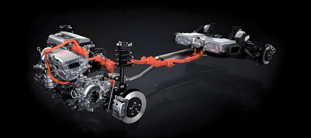
The modern hybrid car is a symphony of mechanical and electrical components. In the studied P1+P3 configuration, the powertrain consists of an engine driveline (a 1.5T engine, dual-mass flywheel, clutch, reduction gear, and differential) and a drive motor driveline (a P3 motor, reduction gear, and differential), with additional systems like the P1 generator axis and oil pump axes. The parallel mode enables both the engine and the P3 drive motor to provide torque to the wheels, optimizing efficiency at higher speeds. Yet, under light throttle conditions in this mode, an undesirable metallic “clattering” or “rattling” sound often emerges. This noise is indicative of gear impacts within the transmission, where unloaded gears, due to small motor torque, are set into oscillatory motion by torsional excitations from the engine side.
To precisely characterize this issue, comprehensive vehicle testing was conducted. Accelerometers and microphones were strategically placed, including at the driver’s inner ear, the DHT housing, the primary flywheel, and the final driven gear. Synchronized Controller Area Network (CAN) data captured motor torques and vehicle speed. The test procedure involved accelerating briskly to enter parallel mode, then gradually reducing speed to the minimum threshold where the hybrid car remains in parallel mode, followed by a light throttle acceleration. The collected data revealed a distinct broadband noise signature in the interior sound spectrum between 35 and 54 seconds, correlating with the subjective perception of rattle. More strikingly, the vibration signal from the DHT casing showed even clearer transient features, marking the exact onset and duration of the impact events. Analysis of speed and torque signals confirmed the nature of the problem: during light-throttle parallel operation, the torque output from the P3 drive motor is relatively low. This renders the gears on the motor side effectively “idle” or unloaded. These idle gears, possessing inherent rotational inertia and separated by backlash, are excited by the fluctuating torsional input from the engine via the drivetrain, leading to repeated impacts against the mating gear teeth—the fundamental mechanism of gear rattle. Notably, the rattle became pronounced only after the drive motor torque stabilized, highlighting its significant role, whereas the generator torque showed minimal influence.
To systematically explore this phenomenon and evaluate potential solutions, a detailed one-dimensional torsional vibration model of the entire hybrid car driveline was developed using simulation software. The model incorporated all major inertial, stiffness, and damping elements. Crucially, it accounted for nonlinearities such as gear backlashes and spline clearances. Engine excitation was modeled using measured in-cylinder pressure curves and the reciprocating inertia of the slider-crank mechanism. Motor torque excitations were imported from test data. Parameters like rotational inertias were derived from CAD models, stiffnesses from finite element analysis, and damping values from empirical data. The model’s fidelity was verified by comparing simulation outputs with test measurements for parameters like primary flywheel speed and final driven gear speed. While minor discrepancies existed due to simplifications (like ignoring engine cyclic variation and assuming nominal backlash values), the overall trends and amplitude levels matched satisfactorily, validating the model for qualitative and comparative analysis of the gear rattle behavior in the hybrid car.
The core of the diagnostic study involved a thorough parameter sensitivity analysis. A fishbone diagram was constructed to map all potential influencing factors, which can be broadly categorized into: control strategy (e.g., torque coordination, parallel mode entry speed), excitation sources (engine torsional excitation, motor torque ripple), isolation components (dual-mass flywheel stiffness/damping/inertia, torsional vibration damper properties), and transmission design (gear inertias, backlash, mesh stiffness, spline clearance). To quantify the rattle intensity in simulation, a dedicated metric was formulated. Since the angular acceleration of the input shaft adjacent to the idle gears directly reflects the impact forces, it was chosen as the evaluation parameter. The metric, denoted as \( r \), is calculated by squaring the angular acceleration, averaging it over time, and then taking an arithmetic mean over the data period:
$$ r = \frac{1}{N} \sum_{i=1}^{N} \left( \frac{1}{\Delta T} \int_{\Delta T} A_i(t)^2 \, dt \right) $$
where \( A_i(t) \) is the squared angular acceleration of the input shaft, \( \Delta T \) is the sampling interval, and \( N \) is the total number of data points. A higher \( r \) value indicates more severe gear rattle. The simulation model was then run repeatedly, varying one parameter at a time within a plausible range while keeping others constant, to observe its effect on \( r \). The results of this systematic analysis are summarized in the table below, which classifies parameters based on their influence trend.
| Influence Trend | Parameters | Qualitative Effect on Rattle (as parameter increases) |
|---|---|---|
| Rattle Decreases | Parallel Mode Entry Vehicle Speed | Decreases |
| P3 Drive Motor Torque (absolute value) | Decreases | |
| Secondary Flywheel (DMF) Inertia | Decreases | |
| Idle Gear Inertia | Decreases | |
| Rattle Increases | Torsional Damper (TVD) Inertia | Increases |
| DMF Damping | Increases | |
| Gear Backlash | Increases | |
| Gear Mesh Stiffness | Increases | |
| Spline Clearance | Increases | |
| P3 Motor Rotor Inertia | Increases | |
| No Clear Trend | Crankshaft Inertia, TVD Stiffness, DMF Primary Stiffness, P1 Rotor Inertia, P3 Torque Ripple | Uncertain or negligible |
From this, the parameters with the most pronounced and consistent influence were identified. To prioritize them for engineering optimization, a sensitivity ranking was performed by calculating the percentage change in the rattle metric \( r \) per unit change in each parameter. The results are presented in the following table.
| Rank | Parameter | Relative Sensitivity (High to Low) | Remarks |
|---|---|---|---|
| 1 | P3 Drive Motor Torque Magnitude | Highest | Larger torque loads the gear, damping relative motion. |
| 2 | Parallel Mode Entry Vehicle Speed | Very High | Higher speed changes operating point and system dynamics. |
| 3 | Gear Backlash | High | Directly defines the impact travel distance. |
| 4 | Secondary Flywheel (DMF) Inertia | Moderately High | Increases kinetic energy on engine side, affecting vibration transmission. |
The underlying physics can be elucidated through a simplified dynamic model of the gear impact process. Consider the system with an input (driving) gear and an idle (driven) gear connected through a torsional spring-damper element representing the shaft and a backlash nonlinearity. The equation of motion for the input side can be expressed as:
$$ I_1 \ddot{\theta}_1 + C (\dot{\theta}_1 – \dot{\theta}_2) + K (\theta_1 – \theta_2) + F_{nl}(\theta_1, \theta_2, b) = T_{\text{input}}(t) $$
where \( I_1 \) is the input inertia, \( \theta_1 \) and \( \theta_2 \) are angular displacements, \( C \) and \( K \) are damping and stiffness, \( b \) is the backlash size, \( F_{nl} \) is the nonlinear contact force due to backlash (zero within the backlash, stiff impact outside it), and \( T_{\text{input}}(t) \) is the fluctuating input torque. The idle gear motion is governed by:
$$ I_2 \ddot{\theta}_2 + C (\dot{\theta}_2 – \dot{\theta}_1) + K (\theta_2 – \theta_1) – F_{nl}(\theta_1, \theta_2, b) = T_{\text{load}} $$
where \( I_2 \) is the idle gear inertia and \( T_{\text{load}} \) is the constant load torque (small from the motor). When \( T_{\text{load}} \) is very small, the system is prone to repeated separations and impacts. The impact force is proportional to the relative acceleration jump across the backlash. Parameters like increased \( T_{\text{load}} \) (P3 torque) effectively bias the gear pair into continuous contact, reducing the chance of separation. Increased secondary flywheel inertia \( I_{\text{DMF2}} \) alters the torsional natural frequencies and can attenuate the transmission of specific engine orders to the gearbox. A higher entry vehicle speed for the parallel mode in a hybrid car often corresponds to a different engine operating point with potentially lower torsional excitation or a change in the gear ratio engagement, altering the forcing function’s relationship to the system modes.
Based on the sensitivity analysis, three primary optimization directions were selected, considering engineering feasibility and cost. Directly controlling gear backlash to extremely tight tolerances is manufacturally challenging and expensive. Therefore, the focus was on control strategy and component modification. The proposed solutions are: Strategy A: Increase the absolute torque command to the P3 drive motor during light-throttle parallel operation from a minimal value to a defined floor, e.g., 30 Nm. Strategy B: Raise the vehicle speed threshold for entering/ sustaining parallel mode, for instance, from 60 km/h to 70 km/h. Strategy C: Increase the rotational inertia of the secondary side of the dual-mass flywheel (DMF), for example, from 0.007 kg·m² to 0.015 kg·m². The expected effectiveness of each strategy was first predicted using the validated simulation model. The results, in terms of percentage reduction in the rattle metric \( r \), are compiled below.
| Optimization Strategy | Parameter Change | Predicted Reduction in Rattle Metric \( r \) | Primary Mechanism |
|---|---|---|---|
| A: Increase P3 Motor Torque | Torque floor raised to 30 Nm | 59.8% | Prevents gear separation by applying constant load. |
| B: Raise Parallel Mode Speed | Entry speed from 60 to 70 km/h | 54.5% | Shifts operating point away from critical excitation region. |
| C: Increase DMF Secondary Inertia | Inertia from 0.007 to 0.015 kg·m² | 47.7% | Filters engine torsional vibrations before transmission. |
Subsequent vehicle tests confirmed these predictions. For strategy C, a手工 prototype with an added inertia ring on the secondary flywheel was fabricated. The results were striking: the peak housing vibration amplitude, which was around ±15g (where g is gravity) in the baseline condition, dropped to approximately ±5g with strategy A, ±6g with strategy B, and ±8g with strategy C. The broadband noise component inside the hybrid car cabin was subjectively rated as significantly improved. This objective and subjective validation confirms the efficacy of the proposed approaches and the robustness of the simulation-based rattle metric \( r \). However, a holistic engineering assessment is crucial. Each strategy carries trade-offs: increasing P3 motor torque may slightly reduce electric efficiency and increase engine load, potentially affecting fuel economy and engine noise. Raising the parallel mode speed threshold might limit the use of the engine for driving at lower speeds, possibly impacting acceleration performance and overall energy management strategy. Increasing the DMF secondary inertia could affect clutch engagement smoothness and engine start-up dynamics. Therefore, the final implementation in a production hybrid car requires a balanced compromise, often involving fine-tuning these parameters within an acceptable range to achieve the best NVH performance without unduly sacrificing other vehicle attributes.
In conclusion, this comprehensive study successfully diagnosed the gear rattle issue in a P1+P3 hybrid car during light-throttle parallel operation. The integration of experimental testing and simulation modeling proved to be a powerful methodology. The rattle was definitively identified as originating from the impact of idle gears on the drive motor side, excited by engine torsional vibrations. A systematic sensitivity analysis revealed that the P3 drive motor torque, the parallel mode entry vehicle speed, and the secondary flywheel inertia are among the most influential and practically adjustable parameters. The proposed optimization strategies—modulating motor torque, adjusting the speed threshold for parallel mode, and increasing DMF secondary inertia—were all demonstrated to significantly mitigate the rattle, with validation from both simulation and physical tests. Furthermore, the development of a quantitative rattle metric based on input shaft angular acceleration provides a valuable tool for future NVH development work on hybrid car transmissions. This work underscores the importance of a systems-level approach to NVH in complex hybrid powertrains, where control strategy and hardware design must be co-optimized to deliver not only efficiency and performance but also the refined quietness expected by drivers of modern hybrid cars.