
The global transition towards sustainable transportation has positioned the battery electric vehicle (BEV) at the forefront of automotive innovation. Central to the performance, safety, and longevity of a battery electric vehicle is its lithium-ion battery pack. These batteries are favored for their high energy density and cycle life but are intrinsically sensitive to operating temperature. Excessive heat or significant temperature gradients within a battery pack can accelerate degradation, reduce usable capacity, and in extreme cases, lead to thermal runaway—a critical safety hazard. Consequently, an effective Battery Thermal Management System (BTMS) is indispensable for any modern battery electric vehicle.
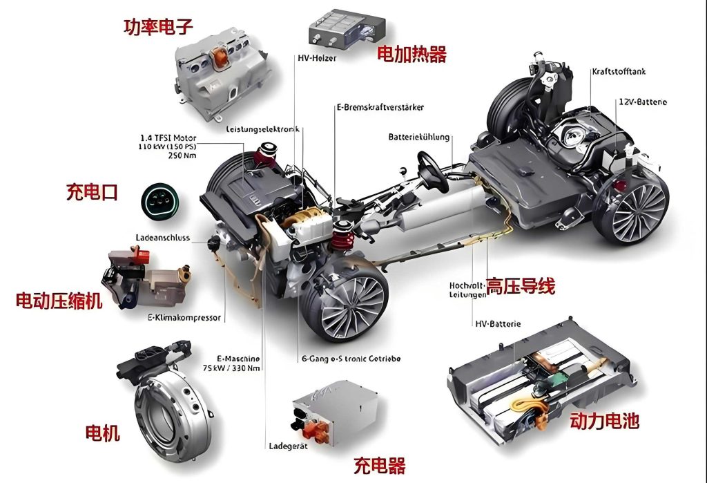
Among various cooling strategies, the direct cooling BTMS, which utilizes the evaporation of a refrigerant in direct contact with a cooling plate attached to the battery, has gained prominence. This system offers advantages such as high heat transfer efficiency due to the latent heat of vaporization, compactness, and effective performance under high ambient temperatures. While substantial research has been conducted on direct cooling BTMS, a significant portion of it is limited to evaluating thermal performance under constant environmental conditions (e.g., 25°C or 30°C) and fixed, high discharge rates (e.g., 1C, 3C). These studies often focus on metrics like the maximum temperature ($T_{max}$) and the maximum temperature difference ($\Delta T_{pack}$) of the battery pack. However, the real-world operation of a battery electric vehicle is characterized by dynamic load profiles—periods of steady cruising, frequent acceleration/deceleration, and regenerative braking. The thermal behavior of the battery pack under these transient, fluctuating power demands is more complex and has not been as thoroughly investigated experimentally.
This study aims to bridge this gap by experimentally evaluating the performance of a direct cooling BTMS for a prismatic lithium-ion battery pack under three representative dynamic driving profiles. We move beyond the conventional metrics to provide a more nuanced analysis of thermal homogeneity by introducing and evaluating longitudinal (within a single cell) and transverse (across the pack at specific heights) temperature differences. Furthermore, we identify a thermal management challenge under aggressive acceleration profiles and propose a practical, engineering-feasible solution involving the integration of aluminum fins to enhance heat spreading, thereby improving the overall thermal uniformity and safety of the system for battery electric vehicle applications.
Experimental Methodology and System Description
1.1 Direct Cooling BTMS Experimental Platform
The core of the experimental setup is a refrigerant-based direct cooling loop dedicated to battery thermal management. The system comprises key components analogous to those in a battery electric vehicle: a variable-speed compressor, a condenser, an internal heat exchanger, an electronic expansion valve (EEV), and the battery cooling plate. A separate, parallel circuit exists for cabin air conditioning, but for this study, only the battery cooling loop was activated. The cooling plate, with dimensions 450 mm × 295 mm × 23 mm, is fabricated with an embedded serpentine copper tube (outer diameter: 10 mm). The entire experimental platform was housed inside a walk-in constant temperature and humidity chamber to provide precise and stable ambient conditions (set to 25°C, 30°C, and 35°C for different test cases). To minimize the influence of ambient airflow within the chamber on the battery pack’s thermal behavior, the pack and cooling plate assembly were enclosed in an insulated box.
1.2 Battery Pack and Instrumentation
The battery pack consisted of twelve 52 Ah prismatic lithium-ion cells connected in series (12S configuration), resulting in a nominal voltage of 38.4V. The cells were arranged in a 2 × 6 matrix and placed on the flat surface of the cooling plate. A 2 mm-thick layer of thermally conductive but electrically insulating silicone grease was applied between the cells and the cooling plate to minimize contact thermal resistance. The battery pack was cycled using a Neware battery tester, which controlled the charge/discharge protocols and recorded electrical parameters (voltage, current, capacity).
Surface temperatures were monitored at strategic locations using K-type thermocouples. Six thermocouples were attached to the surfaces of selected cells to capture both longitudinal and transverse temperature variations. An additional thermocouple was placed on the cooling plate surface near the refrigerant outlet. All temperature data was logged at a frequency of 1 Hz. The positioning was designed to diagnose thermal inhomogeneity: points at 1 cm and 9 cm heights from the bottom on the same cell axis captured longitudinal gradients, while points at the same height across different cells captured transverse gradients influenced by the refrigerant flow path.
1.3 Dynamic Operating Conditions
To simulate real-world driving, three distinct dynamic discharge profiles were designed, moving beyond simple constant-current tests. These profiles are summarized in Table 1.
| Operating Condition | Description | Total Discharge Time |
|---|---|---|
| Steady Operation | Constant discharge at 0.5C (26 A) | 2400 s (40 min) |
| Alternating Load Operation | Cyclic profile: 1C (52 A) for 60 s, followed by 0.5C (26 A) for 540 s. Repeated for 6 cycles. | 3600 s (60 min) |
| Progressive Acceleration | Sequentially increasing load: 0.5C (26 A) for 300 s, then 1C (52 A) for 300 s, and finally 1.5C (78 A) for 300 s. | 900 s (15 min) |
Prior to each discharge test, the battery pack was charged to 100% State of Charge (SOC) using a constant-current constant-voltage (CC-CV) protocol. The direct cooling system was controlled to maintain a constant superheat of 6°C at the cooling plate outlet by modulating the EEV, ensuring efficient evaporator operation and compressor safety.
1.4 Thermal Performance Evaluation Metrics
A comprehensive set of metrics was used to evaluate the BTMS performance, providing deeper insight than just peak temperature.
- Maximum Pack Temperature ($T_{max}$): The highest temperature recorded among all battery surface thermocouples.
$$ T_{max} = \max(T_1, T_2, …, T_n) $$ - Maximum Pack Temperature Difference ($\Delta T_{pack}$): The difference between the highest and lowest temperatures within the entire pack.
$$ \Delta T_{pack} = T_{h} – T_{l} $$
where $T_h$ is the highest pack temperature and $T_l$ is the lowest. - Single Cell Longitudinal Temperature Difference ($\Delta T_{cell}$): The temperature difference between the top and bottom measurement points on a single cell. This indicates how effectively heat is conducted vertically away from the cell’s core to the cooling plate.
$$ \Delta T_{cell} = T_{a} – T_{b} $$
where $T_a$ and $T_b$ are the top and bottom temperatures of a specific cell, respectively. - Pack Transverse Temperature Difference ($\Delta T_{h}$): The temperature difference across the battery pack at a specified height (e.g., 1 cm or 9 cm from the bottom). This reveals uneven cooling along the refrigerant flow path.
$$ \Delta T_{h} = T_{i-u} – T_{i-d} $$
where $T_{i-u}$ and $T_{i-d}$ are the highest and lowest temperatures at height $i$, respectively.
The generally accepted safe operating limits for lithium-ion batteries in a battery electric vehicle are $T_{max} < 50$°C and $\Delta T_{pack} < 5$°C.
Results and Discussion: Base System Performance
2.1 Performance Under Steady Operation
Under the mild 0.5C steady discharge, the direct cooling BTMS demonstrated effective temperature control across all tested ambient temperatures. The $T_{max}$ values peaked at 26.7°C, 30.6°C, and 35.9°C for ambient temperatures of 25°C, 30°C, and 35°C, respectively, well within the safe limit. After the initial rise, the cooling power of the system balanced the heat generation, causing temperatures to gradually decrease. The $\Delta T_{pack}$ stabilized at low values of 2.8°C, 3.0°C, and 3.5°C, also meeting the homogeneity requirement. Both $\Delta T_{cell}$ and $\Delta T_{h}$ remained below 3°C and 1°C, respectively, indicating good thermal uniformity under this low-stress condition. This confirms the system’s adequacy for handling the thermal loads associated with steady-speed cruising in a battery electric vehicle.
2.2 Performance Under Alternating Load Operation
The alternating load profile, simulating stop-and-go traffic or varying driving demands, presented a more challenging but manageable scenario. The $T_{max}$ showed periodic peaks corresponding to the high-load (1C) segments, reaching maximum values of 26.6°C, 31.0°C, and 35.7°C. The system was capable of removing the accumulated heat during the subsequent low-load periods, as evidenced by the temperature decline. While $\Delta T_{pack}$ saw spikes up to approximately 6-7°C during transitions, it showed a stabilizing trend. The $\Delta T_{cell}$ and $\Delta T_{h}$ metrics remained well-controlled, under 2°C and 1°C respectively. This indicates that the direct cooling BTMS possesses the dynamic response necessary to handle intermittent high-power demands typical in urban driving for a battery electric vehicle.
2.3 Challenge Revealed: Progressive Acceleration Condition
The progressive acceleration condition, designed to simulate sustained aggressive driving (e.g., highway merging or spirited driving), exposed a significant limitation of the base cooling plate configuration. As the discharge rate escalated to 1.5C, the heat generation rate outpaced the system’s ability to uniformly dissipate it. The results, summarized in Table 2, highlight the severity of the issue.
| Ambient Temp. | $T_{max}$ (°C) | $\Delta T_{pack}$ (°C) | Max $\Delta T_{cell}$ (°C) | Max $\Delta T_{h}$ (°C) |
|---|---|---|---|---|
| 25°C | 34.1 | 7.8 | 8.0 | ~3.0 |
| 30°C | 42.1 | 13.6 | 10.5 | ~5.0 |
| 35°C | 49.8 | 16.5 | 11.2 | 5.9 |
At a 35°C ambient temperature, the $T_{max}$ approached the dangerous 50°C threshold, and the $\Delta T_{pack}$ of 16.5°C far exceeded the 5°C guideline. More critically, the $\Delta T_{cell}$ for a central cell reached 11.2°C, indicating severe longitudinal heat buildup. The high $\Delta T_{h}$ at the 1 cm height (5.9°C) further indicated poor lateral heat spreading from cells located near the refrigerant outlet (warmer) to those near the inlet (cooler). This thermal inhomogeneity poses a direct threat to the balance, lifespan, and safety of the battery pack in a battery electric vehicle operating under strenuous conditions.
The primary cause was identified as insufficient thermal conductance between the cell’s upper regions and the cooling plate. The single-point contact at the base created a long, restrictive heat conduction path, leading to a large temperature gradient from the cell’s core (where heat is generated) to the cooled surface.
Improvement Strategy: Integration of Heat Spreader Fins
To address the longitudinal heat transfer bottleneck without redesigning the entire cold plate or resorting to complex multi-sided cooling (which can pose electrical insulation challenges), a simple yet effective mechanical solution was implemented: the addition of aluminum heat spreader fins. A thin aluminum plate (360 mm × 179 mm × 2 mm, thermal conductivity ~202 W/m·K) was inserted between the battery pack and the cooling plate, with thermal grease applied on both interfaces. The fins serve two crucial functions:
- Enhance Longitudinal Conduction: They provide an additional, lower-resistance lateral path for heat to travel from the upper portions of the cells down to the cooling plate.
- Improve Transverse Homogeneity: They help distribute heat more evenly across the plane of the cooling plate, mitigating the temperature variation caused by the refrigerant warming up along its flow path.
The modified assembly was then subjected again to the most demanding test case: the progressive acceleration profile at a 35°C ambient temperature.
Results with Fins: Enhanced Thermal Homogeneity
The incorporation of the aluminum fins led to a dramatic improvement in all thermal performance metrics, as detailed in Table 3 and illustrated in the comparative analysis below.
| Performance Metric | Without Fins | With Aluminum Fins | Improvement |
|---|---|---|---|
| $T_{max}$ (°C) | 49.8 | 40.9 | ↓ 8.9°C (17.9%) |
| $\Delta T_{pack}$ (°C) | 16.5 | 5.0 | ↓ 11.5°C (69.7%) |
| Max $\Delta T_{cell}$ (°C) | 11.2 | 4.6 | ↓ 6.6°C (58.9%) |
| Max $\Delta T_{h}$ (at 1cm) (°C) | 5.9 | 1.2 | ↓ 4.7°C (79.7%) |
The effectiveness of the fins can be quantified by considering the enhancement in effective thermal conductance. The longitudinal temperature gradient is driven by the heat generation rate $\dot{Q}_{gen}$ and resisted by the total thermal resistance $R_{total}$ between the cell core and the coolant.
$$ \Delta T_{cell} \propto \dot{Q}_{gen} \times R_{total} $$
Without fins, $R_{total}$ is dominated by the conduction resistance through the cell and the interface to the cold plate. The fin introduces a parallel conductive path, significantly reducing the overall resistance. The improvement in $\Delta T_{cell}$ from 11.2°C to 4.6°C signifies that the effective $R_{total}$ was reduced by approximately 59%, assuming similar $\dot{Q}_{gen}$.
Furthermore, the fins promoted lateral heat spreading, effectively “short-circuiting” the temperature difference between cells over the warmer and cooler sections of the cooling plate. This is why $\Delta T_{h}$ was reduced so markedly, from 5.9°C to 1.2°C. The result is a battery pack where all cells experience a much more similar thermal environment, which is critical for maintaining voltage balance and uniform aging in a series-connected string within a battery electric vehicle.
With the fins, the $T_{max}$ was suppressed to a safe 40.9°C, and crucially, the $\Delta T_{pack}$ was brought within the 5°C guideline. This transformation demonstrates that the direct cooling BTMS, when augmented with appropriate heat-spreading elements, can successfully manage even the severe thermal loads of aggressive acceleration scenarios.
Conclusion
This experimental study provides a comprehensive evaluation of a direct cooling battery thermal management system under dynamic operating conditions representative of real-world battery electric vehicle use. The key findings are:
- The direct cooling BTMS is fully capable of maintaining safe and uniform temperatures during steady, low-power operation and alternating, moderate-power load cycles typical of city driving in a battery electric vehicle.
- Under a sustained progressive acceleration profile simulating high-stress driving, the base system with a single-sided cooling plate exhibited significant thermal limitations. At a 35°C ambient, the battery pack approached a critical maximum temperature (49.8°C) and suffered from excessive internal temperature differences ($\Delta T_{pack}=16.5°C$, $\Delta T_{cell}=11.2°C$), highlighting a risk scenario for battery electric vehicle performance and safety.
- The integration of simple aluminum heat spreader fins between the battery pack and the cooling plate proved to be a highly effective and engineering-practical solution. The fins dramatically improved longitudinal heat conduction from the cell bodies and enhanced transverse temperature uniformity across the pack.
- With the fins installed, the thermal performance under aggressive acceleration was recovered to within safe limits: $T_{max}$ was reduced to 40.9°C and $\Delta T_{pack}$ was brought down to 5.0°C. Both longitudinal ($\Delta T_{cell}$) and transverse ($\Delta T_{h}$) homogeneity were vastly improved.
This work underscores the importance of evaluating BTMS performance under dynamic, high-power conditions that truly stress the system. It also demonstrates that practical design enhancements, such as integrated heat spreaders, can robustly extend the operational envelope of a direct cooling BTMS. Ensuring such thermal robustness is paramount for the reliability, longevity, and safety of the battery packs that power the future of the battery electric vehicle.