
The evolution of the battery electric vehicle (BEV) has transcended mere electrification of the powertrain. The advent of distributed-drive architectures, where each wheel is independently actuated by an electric motor, represents a paradigm shift in vehicle dynamics control. This inherent capability for precise, individual wheel torque control fundamentally alters the relationship between propulsion and stability. My focus centers on the torque distribution strategy—the intelligent algorithm that decides how much force each wheel delivers—and its profound, direct impact on chassis stability. In high-speed maneuvers or on low-friction surfaces, the risk of losing directional control remains a critical challenge. Traditional centralized drives lack the granularity to correct imbalances between wheels instantaneously. Therefore, the dynamic optimization of torque allocation emerges not merely as an enhancement but as the central nervous system for active safety in modern battery electric vehicles. This discussion delves into the coupling mechanisms between various allocation strategies and the chassis’s dynamic response, aiming to conceptualize intelligent models that adapt to extreme conditions and ultimately expand the safety boundaries of the distributed-drive battery electric vehicle.
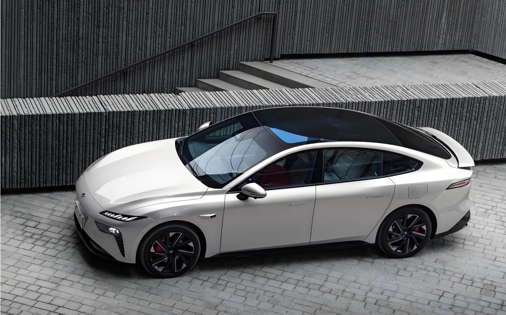
The distributed-drive system redefines the vehicle’s physical architecture. Its core principle is the decoupling of wheel torque, moving away from the mechanical constraints of differentials and drive shafts. This system is a symphony of coordinated components, each playing a critical role in enabling stability-focused control.
| System Module | Key Components | Function & Relevance to Stability |
|---|---|---|
| Propulsion Unit | In-wheel motor / In-board motor with short axle | Provides independent torque source per wheel. In-wheel motors reduce unsprung mass but face durability challenges, while in-board motors offer a compromise between handling refinement and control bandwidth. |
| Energy System | High-voltage battery pack, Power Control Module (PCM) | Supplies peak power demanded by aggressive stability interventions. The PCM must dynamically manage discharge rates to prevent overheating during sustained corrective actions. |
| Transmission | Reduction gearset, Constant-velocity joint | Amplifies motor torque at low speeds and transmits it reliably even at large steering angles, ensuring force delivery is never interrupted during cornering. |
| Control System | Vehicle Control Unit (VCU), Motor Controller Cluster | The brain and nerves. The VCU calculates total demand and optimal distribution; the controllers execute commands at each wheel with millisecond latency. |
Chassis stability in this context is a multi-dimensional target. It is the vehicle’s ability to maintain the driver’s intended path while preserving a safe attitude and maximizing the use of available tire-road friction. We can decompose it into three interlinked but distinct objectives, each with quantifiable metrics.
| Stability Dimension | Definition & Goal | Key Quantifiable Metrics |
|---|---|---|
| Directional Stability (Yaw Stability) | Ability to follow the steering input and desired yaw rate. | Yaw rate error: $$e_r = r_{desired} – r_{actual}$$; Sideslip angle at the center of gravity: $$\beta$$. |
| Attitudinal Stability (Roll Stability) | Ability to prevent excessive body roll and potential rollover. | Vehicle roll angle: $$\phi$$; Load transfer ratio between left and right wheels. |
| Force Stability (Traction Stability) | Ability to optimize longitudinal force generation without inducing excessive wheel slip. | Wheel slip ratio: $$\lambda = \frac{\omega R – V_x}{max(\omega R, V_x)}$$, where $$\omega$$ is wheel speed, $$R$$ is tire radius, and $$V_x$$ is longitudinal velocity. |
The torque distribution strategy directly manipulates these metrics. Its influence operates through several coupled physical mechanisms. The first is the regulation via longitudinal force distribution. By creating a differential drive force between the left and right wheels, a direct yaw moment ($$M_z$$) can be generated to correct the vehicle’s orientation. This moment is calculated as:
$$M_z = \frac{d}{2} (F_{x,rr} + F_{x,fr} – F_{x,rl} – F_{x,fl})$$
where $$d$$ is the average track width, and $$F_{x,ij}$$ is the longitudinal tire force for each wheel (front/rear, left/right). On a split-μ surface (e.g., ice on one side, asphalt on the other), a battery electric vehicle can mitigate pull-by reducing torque on the low-friction side and increasing it on the high-friction side, actively countering the undesired yaw moment.
The second mechanism involves the intricate coupling of longitudinal and lateral forces. A tire’s friction circle (or ellipse) model dictates that the combined longitudinal and lateral force it can produce is bounded:
$$( \frac{F_x}{\mu_x F_z} )^n + ( \frac{F_y}{\mu_y F_z} )^n \leq 1$$
where $$F_x$$ and $$F_y$$ are longitudinal and lateral forces, $$F_z$$ is vertical load, μ are friction coefficients, and *n* is an shaping factor (often ~2). During aggressive cornering in a battery electric vehicle, indiscriminately applying high drive torque to the outer wheels consumes the tire’s grip capacity, leaving less margin for generating necessary lateral force, leading to understeer. An intelligent distribution strategy must allocate torque to manage this coupling, often limiting outer wheel torque during transient cornering to preserve lateral grip.
Third is the mechanism for maintaining stability under high-dynamic transients. This requires a hierarchical control approach. An upper-layer controller, often based on a reference model (like a linear bicycle model), calculates the stabilizing yaw moment required:
$$\Delta M_{z,des} = I_z (\dot{r}_{des} – \dot{r}_{act}) + …$$
where $$I_z$$ is vehicle yaw inertia. A lower-layer, optimal allocation controller then distributes wheel torques to generate this moment while respecting constraints like motor torque limits and the friction ellipse. A common formulation is to solve a constrained optimization problem:
$$\min_{T_i} \sum_{i=1}^{4} ( \frac{T_i}{T_{i,max}} )^2$$
subject to:
$$ \frac{d}{2} (T_{rr} + T_{fr} – T_{rl} – T_{fl}) / R_{eff} = \Delta M_{z,des}$$
$$T_{min} \leq T_i \leq T_{max}$$
where $$T_i$$ is the torque command to each motor, and $$R_{eff}$$ is the effective tire radius. This minimizes the utilization of motor torque reserves while achieving the desired stabilization.
The optimization of these strategies for the battery electric vehicle platform proceeds along several critical vectors. Real-time performance is paramount. The control loop must be faster than the vehicle’s mechanical time constants. This demands hardware-software co-design: multi-core processors for parallel computation of wheel dynamics, deterministic real-time operating systems, and high-bandwidth communication networks (e.g., Ethernet) to reduce latency from sensor to actuator to under 10 milliseconds.
Furthermore, the strategy must be multi-objective. Stability is the primary objective, but efficiency and component wear are crucial for a practical battery electric vehicle. The allocation problem thus becomes a weighted optimization. We can define a comprehensive cost function *J*:
$$J = w_1 \cdot || \Delta M_z – \Delta M_{z,des} ||^2 + w_2 \cdot \sum_{i=1}^{4} P_{loss}(T_i, \omega_i) + w_3 \cdot \sum_{i=1}^{4} (F_{z,i} \cdot \mu_{utilization,i})^2$$
where $$w_1, w_2, w_3$$ are weighting factors prioritizing yaw control, motor power loss, and tire wear (approximated via load and friction utilization), respectively. The table below contrasts strategy focus under different scenarios:
| Driving Scenario | Primary Stability Goal | Secondary Optimization Goal | Typical Torque Distribution Bias |
|---|---|---|---|
| High-speed lane change on dry road | Minimize yaw rate overshoot, control sideslip. | Minimize energy consumption. | Moderate differential torque front/rear and left/right to generate damping yaw moment. |
| Acceleration on split-μ surface | Maintain straight-line trajectory, prevent spin. | Maximize total traction force. | Significantly reduce torque on low-μ wheels; balance torque side-to-side to cancel yaw moment. |
| Aggressive cornering on wet road | Manage understeer/oversteer, stay within friction ellipse. | Prevent excessive inner wheel spin. | Torque vectoring: positive torque to outer wheels, possibly negative torque (braking) to inner wheels. |
| Steady-state cruising | Maintain baseline stability. | Maximize overall powertrain efficiency. | May revert to front-wheel drive, rear-wheel drive, or equal distribution based on efficiency maps. |
The future direction points towards intelligent and adaptive control. Machine learning algorithms, trained on vast datasets of vehicle dynamics, can learn optimal allocation maps that are non-linear and highly adaptive to road conditions. A neural network controller might approximate the optimal solution to the complex, non-convex allocation problem in real-time:
$$\vec{T}_{optimal} \approx NN(\vec{V}_{vehicle}, \vec{S}_{sensors}, \vec{\theta}_{driver})$$
where the network inputs include vehicle state, sensor data, and driver style parameters. Furthermore, integration with environmental perception (camera, radar) enables predictive stability control. For instance, upon detecting an upcoming low-friction curve, the system for the battery electric vehicle can preemptively adjust the torque distribution map and soften response gains to prepare for a potential stability event, moving from reactive to proactive safety.
In conclusion, the torque distribution strategy is the defining element linking the revolutionary propulsion architecture of a distributed-drive battery electric vehicle to its ultimate dynamic competence and safety. It transforms the vehicle from a passively stable system to an actively stabilized platform. Through precise longitudinal force differentials, it directly corrects yaw deviations. By managing the tire force coupling, it preserves critical lateral grip during demanding maneuvers. And through high-bandwidth, multi-objective optimization, it maintains stability without unnecessarily sacrificing efficiency. The continued evolution of these strategies—through advancements in real-time computing, robust multi-criteria optimization, and embedded intelligence—will unlock the full potential of the battery electric vehicle, ensuring that its superior performance is matched by an equally superior and reassuring level of active safety under all driving conditions. The distributed-drive battery electric vehicle, therefore, stands not just as a symbol of cleaner transportation, but as the vanguard for a new era of vehicle dynamics control where stability is actively synthesized by intelligent torque allocation.