
The proliferation of battery electric vehicle technology has catalyzed significant advancements in propulsion architectures. Among these, distributed drive systems, particularly those utilizing in-wheel motors, represent a paradigm shift due to their capacity for precise, independent, and rapid torque control at each wheel. This inherent advantage makes the battery electric vehicle an ideal platform for implementing sophisticated vehicle dynamics control systems. However, ensuring driving stability, especially during aggressive acceleration or on low-friction surfaces, remains a critical challenge. Instabilities such as excessive wheel slip or unintended yaw motion can compromise safety and performance. This research addresses the straight-line driving stability of a four-wheel-drive battery electric vehicle. We propose a decoupled optimal control strategy that coordinately manages yaw rate and wheel slip while tracking a desired vehicle speed, thereby enhancing straight-line stability.
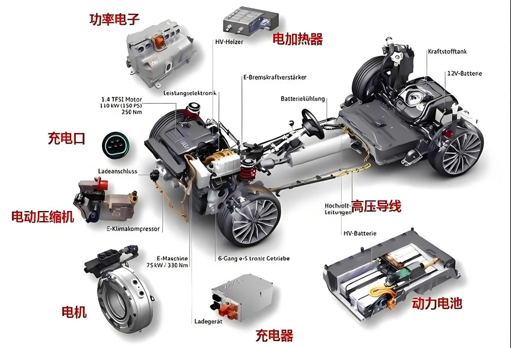
The core of our approach lies in the independent yet coordinated control of three key variables: yaw rate, wheel slip ratio, and longitudinal vehicle speed. We begin by establishing a comprehensive dynamic model for a four-wheel-drive battery electric vehicle. The vehicle and in-wheel motor parameters used for simulation are detailed below.
| Parameter | Value | Unit | Physical Meaning |
|---|---|---|---|
| M | 1300 | kg | Total Vehicle Mass |
| Iz | 1343.1 | kg·m² | Yaw Moment of Inertia |
| a | 1.04 | m | Distance from COG to Front Axle |
| b | 1.56 | m | Distance from COG to Rear Axle |
| Bf | 0.775 | m | Front Track Width (Half) |
| Br | 0.775 | m | Rear Track Width (Half) |
| r | 0.308 | m | Wheel Radius |
| Parameter | Value | Unit | Physical Meaning |
|---|---|---|---|
| Pe | 14 | kW | Rated Power per Motor |
| Pmax | 28 | kW | Peak Power per Motor |
| ne | 800 | r/min | Rated Speed |
| nmax | 1600 | r/min | Maximum Speed |
| Te | 145 | N·m | Rated Torque per Motor |
| Tmax | 290 | N·m | Maximum Torque per Motor |
The required power for the battery electric vehicle to overcome road loads and achieve performance targets (maximum speed, acceleration, gradeability) is given by:
$$
P_t = \frac{1}{\eta} \left( Mgfu \cos \alpha + \frac{Mg u i}{3600} + \frac{C_D A u^3}{21.15} + \delta M u \frac{du}{3.6 dt} \right)
$$
where \(P_t\) is the demanded power, \(M\) is vehicle mass, \(g\) is gravity, \(f\) is rolling resistance coefficient (0.01), \(u\) is speed, \(i\) is road gradient, \(C_D\) is drag coefficient (0.32), \(A\) is frontal area (1 m²), \(\delta\) is rotational inertia coefficient, and \(\eta\) is drivetrain efficiency (0.9). The motor torque characteristic is defined as:
$$
T_m = \begin{cases}
T_{max}, & 0 < n \le n_e \\
9550 \cdot P_{max} / n, & n_e < n \le n_{max}
\end{cases}
$$
Design of the Decoupled Optimal Control System for Straight-Line Stability
The proposed control architecture is hierarchical. The upper-layer controller determines the total longitudinal force required to track the target vehicle speed using a sliding mode control (SMC) approach. Simultaneously, it calculates the corrective yaw moment needed to maintain near-zero yaw rate and the individual wheel torque adjustments for slip prevention. These demands are then decoupled and optimally distributed to the four in-wheel motors of the battery electric vehicle.
Yaw Motion Controller Design
Assuming small lateral motions during intended straight-line driving, a simplified yaw dynamics model is used. The desired yaw rate \(\omega_d\) is zero. The yaw motion is governed by:
$$
I_z \dot{\omega} = \Delta M_z
$$
where \(\Delta M_z\) is the corrective yaw moment. The state-space representation is:
$$
\dot{X} = AX + BU
$$
with \(X = [\omega, \dot{\omega}]^T\), \(A = \begin{bmatrix} 0 & 1 \\ 0 & 0 \end{bmatrix}\), \(B = \begin{bmatrix} 0 \\ 1/I_z \end{bmatrix}\), and \(U = \Delta M_z\). This is discretized using forward Euler method for Model Predictive Control (MPC). The discrete state equation is:
$$
X(k+1) = \bar{A}X(k) + \bar{B}U(k)
$$
where \(\bar{A} = I + TA\), \(\bar{B} = TB\), and \(T\) is the sampling time. Over a prediction horizon \(\rho\), the predicted states are:
$$
\boldsymbol{X}_k = [X(k+1|k)^T, X(k+2|k)^T, …, X(k+\rho|k)^T]^T = \Psi X(k) + \Theta \boldsymbol{U}_k
$$
The MPC cost function minimizes the tracking error of yaw rate while penalizing large control inputs:
$$
\min_{\boldsymbol{U}_k} J = (\boldsymbol{X}_k – \boldsymbol{R}_k)^T Q (\boldsymbol{X}_k – \boldsymbol{R}_k) + \boldsymbol{U}_k^T W \boldsymbol{U}_k
$$
subject to torque constraints \( |U(k+i|k)| \le T_{L, max} \), where \(Q\) and \(W\) are weighting matrices, and \(\boldsymbol{R}_k\) is the reference yaw rate trajectory (zero). The solution yields the optimal corrective yaw moment increment \(\Delta M_z(k)\).
Acceleration Slip Ratio Controller Design
To prevent wheel slip, the slip ratio \(S_{ij}\) for each wheel is monitored. It is defined as:
$$
S_{ij} = \frac{r \omega_{ij} – v_x}{r \omega_{ij}}
$$
where \(\omega_{ij}\) is the wheel angular speed and \(v_x\) is the longitudinal vehicle speed. The target wheel speed \(\omega_{ref}\) corresponding to the optimal slip ratio \(S_{OPT}\) (for maximum longitudinal force) is:
$$
\omega_{ref} = \frac{v_x}{r(1 – S_{OPT})}
$$
A PI controller is employed to generate a corrective torque \(\Delta T_{s,ij}\) to minimize the error \(e_{ij} = \omega_{ref} – \omega_{ij}\):
$$
\Delta T_{s,ij} = k_p e_{ij} + k_i \int e_{ij} dt
$$
If the actual slip ratio is below \(S_{OPT}\), \(\Delta T_{s,ij}\) is set to zero.
Lower-Level Control Allocation and Decoupling
The upper-layer outputs—the total longitudinal force \(F_x^{total}\) from SVC, the yaw moment increment \(\Delta M_z\) from MPC, and the four slip-control torque increments \(\Delta T_{s,ij}\)—must be converted into individual wheel torque commands. This is a constrained optimization problem.
The corrective yaw moment \(\Delta M_z\) is generated by differential longitudinal forces on the left and right wheels. For a battery electric vehicle, this relationship is:
$$
\Delta M_z = \frac{B_f}{2} (\Delta F_{xfr} – \Delta F_{xfl}) + \frac{B_r}{2} (\Delta F_{xrr} – \Delta F_{xrl})
$$
The slip-control torque increments correspond to longitudinal force increments: \(\Delta F_{s,ij} = \Delta T_{s,ij} / r\). The combined control demand vector \(\boldsymbol{v}\) and the control input vector (wheel force increments) \(\boldsymbol{u}\) are:
$$
\boldsymbol{v} = \begin{bmatrix} \Delta M_z \\ \Delta F_{s,fl} \\ \Delta F_{s,fr} \\ \Delta F_{s,rl} \\ \Delta F_{s,rr} \end{bmatrix}, \quad \boldsymbol{u} = \begin{bmatrix} \Delta F_{x,fl} \\ \Delta F_{x,fr} \\ \Delta F_{x,rl} \\ \Delta F_{x,rr} \end{bmatrix}
$$
The relationship is linear: \(\boldsymbol{v} = \boldsymbol{B} \boldsymbol{u}\), where matrix \(\boldsymbol{B}\) incorporates the geometry from the yaw moment equation and the 1/r factor from torque-force conversion. The optimal force increments are found by solving a Quadratic Programming (QP) problem:
$$
\min_{\boldsymbol{u}_{min} \le \boldsymbol{u} \le \boldsymbol{u}_{max}} ||\boldsymbol{W}(\boldsymbol{B}\boldsymbol{u} – \boldsymbol{v})||^2_2
$$
where \(\boldsymbol{W}\) is a diagonal weighting matrix prioritizing yaw or slip control, and \(\boldsymbol{u}_{min/max}\) are constraints based on maximum motor torque and road adhesion. The solution \(\boldsymbol{u}^*\) gives the optimal wheel force increments for stability, which are converted to torque increments \(\Delta T_{ij}^* = \Delta F_{x,ij}^* \cdot r\).
Speed Tracking and Optimal Force Distribution
The total longitudinal force \(F_x^{total}\) required to track the desired speed \(v_{xd}\) is derived from the longitudinal dynamics and computed via Sliding Mode Control (SMC). The sliding surface is \(s_v = v_x – v_{xd}\). Using a saturation function \(sat(\cdot)\) to reduce chattering, the control law is:
$$
F_x^{total} = M \left( \dot{v}_{xd} – k_v sat(s_v/\epsilon) \right) + F_{roll} + F_{aero} + F_{grade}
$$
where \(k_v > 0\), \(\epsilon > 0\), and the resistance forces include rolling, aerodynamic drag, and grade resistance.
This total force, along with the stability-adjusted force from the previous step, must be distributed optimally to the four wheels. We use a second QP algorithm that minimizes the sum of squared tire utilization ratios \(\rho_{ij}\) to ensure efficient use of road adhesion and avoid saturation. The utilization ratio is:
$$
\rho_{ij} = \frac{ \sqrt{ F_{x,ij}^2 } }{ \mu_{ij} F_{z,ij} }
$$
The optimization is formulated as:
$$
\min_{\boldsymbol{F}_{x,min} \le \boldsymbol{F}_x \le \boldsymbol{F}_{x,max}} \boldsymbol{F}_x^T \boldsymbol{W}_\rho \boldsymbol{F}_x \quad \text{subject to} \quad \boldsymbol{1}^T \boldsymbol{F}_x = F_x^{total}
$$
where \(\boldsymbol{F}_x = [F_{x,fl}, F_{x,fr}, F_{x,rl}, F_{x,rr}]^T\), \(\boldsymbol{W}_\rho\) is a weighting matrix based on \(1/(\mu_{ij} F_{z,ij})^2\), and the constraints include motor torque limits and friction ellipse limits. The final torque command to each in-wheel motor of the battery electric vehicle is:
$$
T_{ij, final} = F_{x,ij}^* \cdot r + \Delta T_{ij}^*
$$
Simulation Analysis and Results
The proposed decoupled optimal control strategy was implemented and tested in a MATLAB/Simulink environment under two critical road conditions. The performance was compared against three baseline strategies: 1) “No Control”: Simple PID speed control with even torque split. 2) “Yaw Control”: PID speed control with the proposed yaw MPC only. 3) “Slip Control”: PID speed control with the proposed wheel-slip PI control only. 4) “Proposed Decoupled Control”: Our integrated strategy.
Simulation on High-Adhesion Road (\(\mu = 1.0\))
The battery electric vehicle accelerates from 0 to 72 km/h and maintains speed. All four controllers achieve the target speed within ~8 seconds without overshoot. The yaw rate and lateral deviation (Y-axis displacement) for all methods remain negligible, demonstrating inherent stability on high-grip surfaces. All wheels maintain stable slip ratios without significant spin. The proposed controller shows performance equivalent to the baselines in this ideal scenario.
Simulation on Low-Adhesion Road (\(\mu = 0.2\))
This scenario highlights the superiority of the integrated approach. The vehicle accelerates from 0 to 73 km/h on a slippery surface.
Speed Tracking: The “No Control” and “Yaw Control” strategies exhibit significant speed overshoot (2.8% and 2.5%, respectively) and longer settling times due to wheel spin. The “Slip Control” strategy reduces overshoot to 1.3%. The “Proposed Decoupled Control” strategy effectively suppresses overshoot, allowing the battery electric vehicle to reach and maintain the target speed most rapidly and smoothly.
Yaw Stability: During acceleration, the “No Control” and “Slip Control” vehicles exhibit noticeable yaw rate fluctuations, indicating a loss of directional stability. The “Yaw Control” strategy mitigates this effectively. Our proposed strategy demonstrates the best performance, maintaining a yaw rate closest to zero and virtually eliminating lateral deviation.
Wheel Slip Management: This is the most critical comparison. Under “No Control” and “Yaw Control”, the wheels experience severe slip, with slip ratios rapidly peaking close to 1 (full spin). The “Slip Control” strategy successfully limits the peak slip ratio and brings the wheels back to a stable region faster. The “Proposed Decoupled Control” strategy excels by proactively keeping the slip ratios of all four wheels within a safe, low boundary throughout the acceleration phase, completely preventing unstable wheel spin.
| Control Method | Speed Overshoot (Low-\(\mu\)) | Yaw Rate Stability | Wheel Slip Prevention | Overall Ranking |
|---|---|---|---|---|
| No Control | High (2.8%) | Poor | Poor (Severe Spin) | 4 |
| Yaw Control Only | High (2.5%) | Good | Poor (Severe Spin) | 3 |
| Slip Control Only | Medium (1.3%) | Fair | Good | 2 |
| Proposed Decoupled Control | Very Low / None | Excellent | Excellent | 1 |
Conclusion
This research presents a novel decoupled optimal control strategy for enhancing the straight-line driving stability of a four-wheel-drive battery electric vehicle. By simultaneously controlling yaw rate, wheel slip ratio, and vehicle speed, the system addresses multiple potential instability modes in a coordinated fashion. The hierarchical design leverages Model Predictive Control for yaw stability, PI control for slip prevention, and Sliding Mode Control for speed tracking, with a Quadratic Programming-based optimizer performing efficient and constrained control allocation. Simulation results under both high and low adhesion conditions conclusively demonstrate the strategy’s effectiveness. Compared to isolated yaw or slip control methods, the proposed integrated approach significantly improves acceleration performance, eliminates directional deviations, and most importantly, robustly prevents wheel spin, thereby ensuring superior straight-line stability and safety for the battery electric vehicle. This work provides a comprehensive control framework that fully utilizes the actuation flexibility of in-wheel motor-driven electric vehicles.