
The relentless pursuit of occupant comfort has elevated the vehicle climate control system from a luxury to a fundamental expectation. In the era of electrification, this expectation is further amplified. Owners demand rapid and powerful cooling under the most scorching sun and immediate, ample heat in frigid conditions. For electric cars, the air conditioning system is not merely a comfort feature; it is an intricate component of the vehicle’s broader thermal management strategy, often tasked with managing battery temperature alongside cabin climate. This expanded role, coupled with higher consumer expectations, places immense pressure on the design and validation of climate systems in electric vehicles. The transition from internal combustion engines (ICEs) to electric powertrains presents unique thermal challenges. While the removal of the high-temperature engine, turbocharger, and exhaust system simplifies under-hood thermal management in one respect, it introduces new constraints. The design paradigm for the front end of many electric cars shifts towards aerodynamic, often nearly sealed facias, potentially compromising the cooling airflow critical for the air conditioning condenser. This report details a first-person engineering investigation into a critical air conditioning failure in an electric car under extreme conditions, where Computational Fluid Dynamics (CFD) simulation was instrumental in diagnosing the root cause and validating an effective solution.
The fundamental vapor-compression cycle remains the cornerstone of automotive air conditioning, whether for internal combustion engine vehicles or electric cars. The system comprises four key components: the compressor, condenser, expansion device (valve or tube), and evaporator. The working principle involves the compression, condensation, expansion, and evaporation of a refrigerant. The compressor raises the pressure and temperature of the refrigerant gas. This high-pressure gas then flows to the condenser, where it rejects heat to the ambient air passing through it, condensing into a high-pressure liquid. This liquid passes through an expansion valve, where it undergoes a throttling process, causing a drastic pressure and temperature drop, transforming it into a low-pressure liquid-vapor mixture. This mixture enters the evaporator, absorbs heat from the cabin air blown across it, and completely vaporizes. The cool air is directed into the cabin, while the low-pressure refrigerant gas returns to the compressor to restart the cycle.
The primary distinction for an electric car lies in the compressor technology. Traditional ICE vehicles use a mechanically driven compressor, typically belt-connected to the engine crankshaft. Its speed and cooling capacity are directly tied to engine RPM, leading to compromises: insufficient cooling at idle and potential over-cooling at high speeds. In stark contrast, electric cars employ an electric compressor powered directly by the vehicle’s high-voltage battery. This allows for precise, demand-based control. An electric compressor can operate at a wide range of speeds, from a low of around 800-900 rpm to over 10,000 rpm, enabling both subtle modulation and very high cooling capacity, often exceeding 10 kW. This flexibility is a key advantage for the electric car, allowing it to meet aggressive cabin pull-down targets and manage additional thermal loads. Furthermore, the electric car often integrates the cabin cooling loop with the battery thermal management system. A secondary heat exchanger, commonly called a chiller, allows cold refrigerant from the main AC loop to cool the battery coolant circuit. While this enhances overall energy efficiency and battery performance, it adds complexity to the control strategy and can divert cooling capacity from the cabin, a trade-off that must be carefully managed in the electric car’s thermal architecture.
The under-hood environment, or front compartment, plays a decisive role in air conditioning performance for all vehicles. For an electric car, this area’s design requires a nuanced approach. The absence of major combustion heat sources reduces overall cooling demand for propulsion components. This often leads to designs with smaller or even sealed front grilles to improve aerodynamics—a crucial factor for extending the driving range of an electric car. However, the condenser’s need for ample, cool ambient airflow remains as critical as ever. If the front-end design restricts airflow or promotes poor flow distribution, the condenser cannot reject heat effectively. The consequence is elevated refrigerant pressure and temperature at the condenser outlet. On a pressure-enthalpy diagram, this is seen as a compression process ending at a higher pressure and a condensation process that is incomplete or occurs at a higher temperature. The system’s cooling capacity, $ Q_{cooling} $, is directly compromised. The coefficient of performance (COP), defined as the ratio of cooling effect to compressor work input, drops significantly:
$$ COP = \frac{Q_{cooling}}{W_{comp}} $$
A lower COP means the electric car’s air conditioning system works harder (consuming more valuable battery energy) to provide less cooling. In severe cases, insufficient condenser heat rejection can cause the high-side refrigerant pressure to exceed safety limits, triggering a protective shutdown of the electric compressor—a complete failure of the climate system.
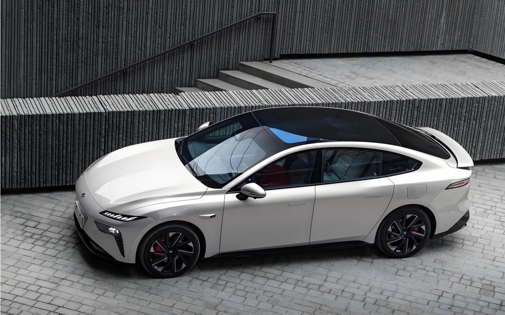
This challenge led to a specific field failure in one of our electric car models. During high-temperature durability testing in a region with ambient temperatures reaching 45°C and ground temperatures exceeding 75°C, a critical fault emerged. During prolonged idle conditions, the cabin temperature failed to decrease satisfactorily. More alarmingly, after 20 to 30 minutes, the air conditioning system would disengage entirely due to the electric compressor shutting down. This was perplexing, as standard environmental chamber tests at 38°C had shown compliant performance. Initial data from the vehicle’s Controller Area Network (CAN bus) revealed the direct cause: the high-side refrigerant pressure was spiking to the system’s maximum protection limit of 28 bar. Concurrently, the temperature at the condenser inlet was recorded at a staggering 77°C and rising. This data pointed unequivocally to catastrophic condenser heat exchange failure. The ambient air available to cool the condenser was itself excessively hot, suggesting severe under-hood heat soak and airflow recirculation. The traditional diagnostic path would involve costly and time-consuming physical prototyping and testing. Instead, we turned to CFD simulation to deconstruct the under-hood flow field virtually.
We initiated a steady-state CFD analysis of the front compartment under idle conditions, simulating the high-temperature environment. The model included detailed geometry of the condenser, radiator (for powertrain cooling), cooling fan, underbody panels, and the surrounding structure. The core governing equations solved were the Navier-Stokes equations for fluid flow and the energy equation for heat transfer. The primary goal was to visualize the airflow paths and identify thermal bottlenecks.
The simulation results were revealing. The streamlines showed chaotic flow patterns within the compartment. A significant portion of the hot air ejected from the condenser and radiator was not expelled efficiently from the underbody. Instead, it formed large-scale vortices and recirculation zones, particularly around the sides of the heat exchangers. This created a “hot air blanket,” causing ambient air to be repeatedly drawn through the condensers, each time at a higher temperature. This recirculation phenomenon explained the 77°C condenser inlet temperature. Furthermore, flow separation and leakage paths around the edges of the heat exchangers meant that not all incoming air was forced through the finned surfaces, reducing effective frontal area. The heat transfer equation:
$$ Q = \dot{m} c_p \Delta T $$
where $ Q $ is heat rejected, $ \dot{m} $ is mass flow rate of air, $ c_p $ is specific heat, and $ \Delta T $ is the air temperature rise across the condenser, clearly shows the double penalty: a reduced effective mass flow rate ($ \dot{m} $) and a minimized temperature potential ($ \Delta T $) due to high inlet air temperature, both collapsing the condenser’s heat rejection capability ($ Q $).
Based on the CFD diagnostics, a two-pronged corrective strategy was formulated and virtually tested. The first was a control parameter change: increasing the maximum allowable speed of the cooling fan by 200 RPM under full duty cycle to boost bulk airflow. The second, and more structural, intervention involved modifying the under-hood aerodynamics based on the CFD insights. Two key changes were designed:
1. The addition of side seal panels or air guides along the vertical edges of the condenser and radiator assembly. These seals were intended to block the major recirculation paths identified by the CFD streamlines, forcing incoming air to pass through the heat exchangers and preventing hot exhaust air from spilling back around the sides to the inlet.
2. Strategic modification of the underbody panels. The CFD showed areas of stagnant flow and high pressure buildup. By creating new exhaust openings or enlarging existing ones in these specific zones, we aimed to provide a low-resistance escape path for the heated air, reducing backpressure and promoting a more through-and-out flow pattern.
We created new CFD models incorporating these design changes. The comparative results were significant. The side seals effectively channeled the flow, drastically reducing the large-scale vortices at the heat exchanger sides. The revised underbody openings allowed the hot air to exit cleanly, diminishing the overall recirculation ratio within the compartment. The table below summarizes the quantitative improvement in condenser performance predicted by the CFD simulations across the different configurations under the simulated idle, high-ambient condition:
| Configuration | Air Mass Flow Rate (kg/s) | Condenser Inlet Air Temp. (°C) | Condenser Outlet Air Temp. (°C) | Air Temp. Rise, ΔT (°C) | Calculated Heat Rejection, Q (kW) |
|---|---|---|---|---|---|
| Baseline Vehicle | 0.51 | 72.4 | 79.0 | 6.6 | 4.71 |
| With Side Seals Only | 0.47 | 61.9 | 70.4 | 8.5 | 5.58 |
| With Underbody Openings Only | 0.47 | 64.4 | 73.3 | 8.9 | 5.69 |
| Combined Solution (Seals + Openings) | 0.50 | 53.9 | 63.7 | 9.8 | 6.81 |
The combined solution predicted a 45% reduction in condenser inlet air temperature (from 72.4°C to 53.9°C) and a corresponding 45% increase in heat rejection capacity (from 4.71 kW to 6.81 kW). This virtual validation provided high confidence before committing to tooling modifications and physical testing.
The final and decisive step was real-world validation on the electric car. The modifications were implemented sequentially. The first test, with only the increased fan speed and underbody openings, showed improvement but not resolution. The compressor no longer shut down, and peak pressure dropped to 25 bar. However, cabin cooling performance remained poor, with an evaporator outlet temperature of 21°C, indicating the core issue of hot air recirculation was not fully addressed. The second test, incorporating the complete package—increased fan speed, underbody openings, and the side seal panels—delivered the definitive result. During an extended idle period over one hour in extreme heat, the air conditioning system operated continuously and stably. CAN data confirmed the success: the peak high-side pressure was dramatically reduced to 19 bar and exhibited a stable, decreasing trend. The front compartment ambient temperature stabilized at a much lower 65°C. Most importantly, the cabin cooling performance was restored, with the evaporator temperature achieving a stable 12°C, confirming effective and robust air conditioning operation in the challenging environment for the electric car.
This case study underscores the critical importance of front-end thermal management in electric car design, particularly for the climate system. The assumption that removing the internal combustion engine eliminates under-hood cooling challenges is a dangerous oversimplification. The electric car’s air conditioning system, with its high-capacity electric compressor and potential battery cooling duties, often has a greater and more consistent need for condenser heat rejection than its ICE counterpart. A holistic, airflow-centric design approach from the outset is essential. This investigation powerfully demonstrates the efficacy of integrating CFD simulation into the development and problem-solving workflow. The CFD model served as a virtual diagnostic tool, accurately pinpointing the physical mechanisms of failure—recirculation and insufficient exhaust flow. It then functioned as a virtual prototyping platform, allowing us to rapidly iterate and quantitatively evaluate corrective measures before any metal was cut. The strong correlation between the CFD predictions (e.g., 45% improvement in heat rejection) and the final test results (stable operation, low pressures, effective cooling) validates the precision and utility of the simulation. For engineers developing the next generation of electric cars, leveraging such virtual engineering tools is not just an efficiency gain; it is a necessity to ensure vehicle systems meet the stringent and multifaceted performance demands of modern electric vehicles, where every watt of energy consumed for cooling directly impacts the vehicle’s core promise: its driving range.