
As a professional deeply involved in the modern electrical infrastructure landscape, I have witnessed firsthand the meteoric rise of the battery electric car. The proliferation of the battery electric car represents a monumental shift in transportation, yet this revolution hinges on a critical, often underappreciated component: the charging infrastructure. The common refrain of “range anxiety” is, in essence, a manifestation of “charging infrastructure anxiety.” While product standards exist, the intricate art and science of designing, engineering, and installing a robust, user-friendly, and future-proof charging ecosystem remain complex. This article delves into the core systems, design calculations, installation imperatives, and forward-looking trends that define a successful battery electric car charging facility project.
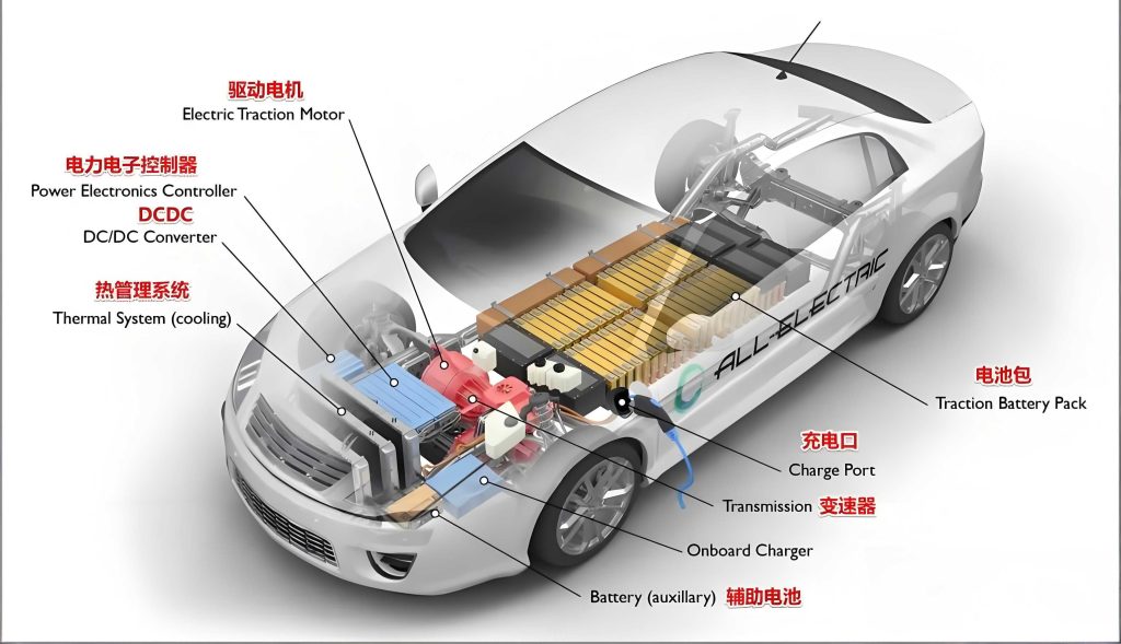
The charging infrastructure for a battery electric car is far more than a simple power outlet. It is an integrated system that interfaces with the grid, manages power delivery, ensures safety, and provides a seamless user experience. A typical system comprises several key layers:
| System Layer | Key Components | Primary Function |
|---|---|---|
| Grid Connection & Energy Supply | Medium Voltage/Low Voltage Substation, Transformers, Switchgear, Power Quality devices (Harmonic filters, Capacitor banks). | Provides the primary electrical service, ensures voltage stability and power quality for the local grid. |
| Energy Management & Distribution | Low Voltage Distribution Boards, Circuit Breakers, Conductors (Cables/Wires), Metering systems. | Distributes power safely to individual charging points, provides circuit protection and energy measurement. |
| Charging Points (EVSE) | AC Chargers (Level 1 & 2), DC Fast Chargers (DCFC), Pantograph systems for heavy-duty vehicles. | The physical interface for the battery electric car, converting and controlling power delivery. |
| Software & Network Backend | Charge Point Management System (CPMS), User Authentication/Roaming platforms, Load Management software. | Enables remote monitoring, user access, payment processing, and dynamic power allocation. |
| Civil & Site Works | Concrete foundations, Cable trenches/conduits, Canopies for weather protection, Lighting, Signage. | Provides the physical housing, safety, and accessibility for all hardware components. |
The heart of the technical design lies in load calculation and power management. A cluster of charging points, especially DC fast chargers, represents a significant and potentially destabilizing load. The fundamental power demand for a station can be modeled. The total instantaneous power demand (Ptotal) is the sum of the power drawn by all active chargers. However, due to stochastic arrival and charging cycles, a diversity factor (kd) is applied.
$$P_{total\_calculated} = k_d \times \sum_{i=1}^{n} P_{charger\_i}$$
Where $P_{charger\_i}$ is the rated power of the i-th charger. The diversity factor $k_d$ is critical and depends on the type of facility (e.g., highway corridor vs. workplace parking). For a station with ten 150 kW DC fast chargers, the non-coincident peak is 1.5 MW. With a prudent $k_d$ of 0.7, the designed supply capacity might be 1.05 MW. Voltage drop is another paramount consideration, especially for long cable runs to distant parking stalls. The approximate voltage drop (VD) for a single-phase AC circuit can be estimated as:
$$VD \approx \frac{2 \times L \times I \times R}{1000}$$
Where $L$ is the one-way cable length in meters, $I$ is the load current in Amperes, and $R$ is the cable resistance in Ω/km. For three-phase balanced loads, the factor 2 is replaced by $\sqrt{3}$. Ensuring VD is within limits (typically 3-5%) is essential for charger efficiency and performance.
Harmonics generated by the power electronics in chargers can pollute the local grid. Total Harmonic Distortion (THD) for current must be evaluated. The current THD is given by:
$$THD_I = \frac{\sqrt{\sum_{h=2}^{50} I_h^2}}{I_1} \times 100\%$$
Where $I_h$ is the RMS current of the h-th harmonic and $I_1$ is the RMS value of the fundamental current. Mitigation often requires active or passive harmonic filters at the distribution board. The thermal management of cables installed in bundles or conduits is also crucial. The corrected ampacity $I_{corr}$ is:
$$I_{corr} = I_{tabulated} \times k_1 \times k_2 \times … \times k_n$$
Where correction factors ($k$) account for ambient temperature, grouping, and installation method. Oversizing cables or providing dedicated conduits for high-power DC circuits is a standard practice to manage heat and reduce losses.
The selection of charging point technology is dictated by the intended use case for the battery electric car. The following table contrasts the primary options:
| Charger Type | Typical Power Level | Connector Standards | Use Case & Design Implication |
|---|---|---|---|
| AC Level 1 | 1.4 – 1.9 kW (120V) | NEMA 5-15 (NA), CEE 7/4 (EU) | Overnight residential charging. Minimal grid impact, uses existing circuits. |
| AC Level 2 | 7 – 22 kW (240V/400V) | SAE J1772 (NA), IEC Type 2 (EU), GB/T (China) | Workplace, commercial, public parking. Requires dedicated circuit and professional installation. |
| DC Fast Charger (DCFC) | 50 – 350 kW (400V+ DC) | CCS1/CCS2, CHAdeMO, GB/T, Tesla NACS | Highway corridors, fleet depots. Requires heavy-duty grid connection, significant cooling, and advanced site planning. |
Installing a charger for a battery electric car is a multi-disciplinary task. Safety is the non-negotiable foundation. All electrical installations must comply with national codes (e.g., NEC Article 625 in the US, IEC 60364 series internationally). Key installation principles include:
- Proper Grounding and Bonding: A low-impedance equipment grounding conductor is mandatory to protect against fault currents, especially critical for DC circuits.
- Cable Management and Protection: High-power DC cables must be routed in rigid metallic conduits for physical protection and to contain electromagnetic fields. Labeling of all cables and circuits is essential.
- Environmental Considerations: Outdoor chargers require NEMA 3R or 4 enclosures. In colder climates, heating elements may be needed for connector handles. Adequate drainage around pedestals is crucial.
- Clearance and Accessibility: Sufficient space must be provided around the charger for vehicle maneuverability and for users with disabilities, adhering to ADA or local accessibility guidelines.
A critical operational challenge is managing the peak demand charges that can cripple the economics of a charging station. Smart Load Management (SLM) systems are the solution. These systems dynamically allocate available power among multiple chargers based on a set priority or first-come-first-served logic. If the total demand approaches the site’s contracted capacity, the SLM can throttle the output of selected chargers (e.g., reducing a 150 kW session to 75 kW) rather than tripping the main breaker. The algorithm for a simple power-sharing scheme can be expressed as:
Let $P_{available}$ be the total site power limit. Let $P_{requested\_i}$ be the power requested by a battery electric car at charger $i$. The system allocates power $P_{allocated\_i}$ such that:
$$\sum_{i=1}^{n} P_{allocated\_i} \leq P_{available}$$
And $P_{allocated\_i} = min(P_{requested\_i}, P_{fair\_share})$, where $P_{fair\_share}$ could be $P_{available} / n_{active}$. More advanced systems use real-time pricing and vehicle State of Charge (SOC) data to optimize.
Looking forward, the infrastructure for the battery electric car is evolving rapidly. Several key trends will shape the next generation of projects:
- Vehicle-to-Grid (V2G) Integration: Future designs must incorporate bidirectional power flow capabilities, allowing a battery electric car to supply power back to the grid during peak hours. This requires advanced inverters and grid interconnection agreements.
- Ultra-Fast Charging (>350 kW): Charging a battery electric car at 400-800 kW demands liquid-cooled cables, mega-watt-scale grid connections, and potentially on-site energy storage or buffer batteries to mitigate grid impact.
- Standardization of Megawatt Charging System (MCS): For electric trucks and buses, the emerging MCS standard (up to 3.75 MW) will dictate entirely new designs for depot and highway charging, involving dedicated high-voltage switchyards.
- Integration with Renewable Energy: Co-locating solar canopies and battery energy storage systems (BESS) with charging stations creates resilient, semi-autonomous microgrids that reduce operational costs and grid dependency.
The successful deployment of charging infrastructure for the battery electric car is a complex symphony of electrical engineering, civil planning, software integration, and forward-looking policy. It requires moving beyond mere product specification to a holistic system-engineering approach. By rigorously applying load calculations, adhering to stringent safety codes, implementing intelligent management software, and planning for technological evolution, we can build the foundational network that will support the full potential of the electric mobility revolution. The journey of every battery electric car begins and ends at a charging point; it is our responsibility to ensure that point is reliable, efficient, and ready for the future.