
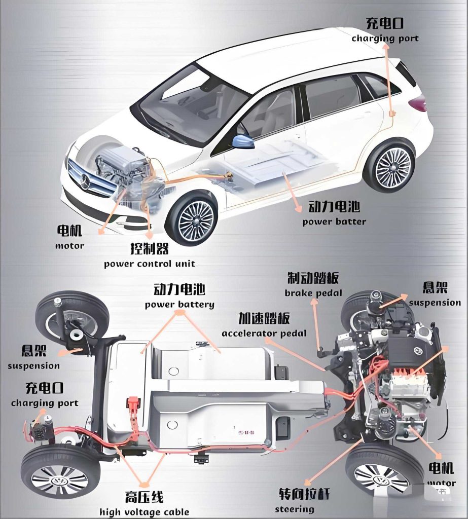
The rapid advancement of new energy vehicles, particularly battery electric cars, is driven by an increasing global demand for renewable and non-polluting energy sources. This evolution places stringent requirements on the core propulsion system—the electric drive motor. For a battery electric car to be competitive and practical, its drive motor must deliver reliable performance across diverse operating conditions, providing sufficient power for acceleration and hill-climbing while simultaneously maintaining high efficiency to maximize driving range. The motor drive system is, therefore, a critical technological pillar for the success of any modern battery electric car. Among various motor topologies, the Parallel Hybrid Excitation Motor (PHEM) exhibits significant potential due to its unique structural and performance advantages, offering a promising solution for next-generation electric vehicles.
A hybrid excitation motor ingeniously combines the benefits of both electrically excited and permanent magnet (PM) machines. It inherits the high power density, high torque output, and high-efficiency characteristics of PM motors, while also incorporating the field-weakening and field-strengthening capabilities of wound-field machines. This allows for effective regulation of the air-gap magnetic field, enabling wide-speed constant power operation and efficient voltage regulation, which are essential for the dynamic performance and energy management of a battery electric car. The key challenge lies in optimally integrating the permanent magnet and electromagnetic excitation sources to achieve efficient magnetic field control, enhance overall performance, and reduce manufacturing costs, which is crucial for widespread adoption in the competitive automotive market, including not only passenger battery electric cars but also utility vehicles like electric tricycles.
This work focuses on the research and development of a parallel hybrid excitation claw-pole motor specifically designed for vehicular applications in new energy vehicles. Hybrid excitation motors are primarily categorized into series and parallel types. The parallel configuration is often preferred for applications in a battery electric car due to its superior power characteristics and enhanced safety; the excitation flux path does not pass through the permanent magnets, preventing irreversible demagnetization under high field-weakening currents. This study proposes a novel electromagnetic structure for a parallel hybrid excitation claw-pole motor. Through in-depth electromagnetic analysis, mathematical modeling, and simulation, the motor’s structure is optimized to improve its torque output, efficiency, and operational range. The primary research methodology employs the Finite Element Method (FEM) for electromagnetic field simulation. By parametrically varying key structural dimensions and observing changes in magnetic field distribution and motor performance, an optimal design is identified. The goal is to provide an efficient, stable, and high-performance motor solution tailored for the propulsion needs of various electric vehicles.
Overall Scheme Analysis of the Parallel Hybrid Excitation Motor
Addressing common challenges in electric vehicles such as low-speed high-torque demand, narrow speed regulation range, and insufficient hill-climbing ability, this paper proposes a parallel claw-pole hybrid excitation motor design. The target performance parameters for the motor are summarized in Table 1, which are essential for a capable battery electric car drivetrain.
| Parameter | Value |
|---|---|
| DC Voltage (V) | 72 |
| Rated Power (kW) | 4 |
| Rated Torque (N·m) | 30 |
| Rated Speed (r/min) | 3000 / 4000 / 5000 |
| Peak Power (kW) | 9.5 |
| Peak Torque (N·m) | 90 |
| Maximum Speed (r/min) | 7500 |
| High-Efficiency Region (%) | >90 |
To meet these specifications, electromagnetic design and optimization are imperative. The initial step involves analyzing the magnetic circuit of the parallel hybrid excitation motor. A simplified magnetic equivalent circuit is crucial for understanding its operation. In a parallel hybrid excitation structure, the total magnetomotive force (MMF) is the parallel combination of the permanent magnet MMF ($F_m$) and the field winding MMF ($F_c$). The key feature is that the flux produced by the field winding does not pass through the permanent magnets, thereby avoiding the risk of demagnetization. The magnetic reluctances include those of the stator ($R_g$), rotor ($R_r$), and the field excitation yoke ($R_{cr}$). The overall magnetic flux $\Phi_{total}$ in the main air-gap path can be conceptually expressed based on the parallel magnetic circuit law:
$$
\Phi_{total} = \frac{F_m}{R_m + R_{ag}} + \frac{F_c}{R_c + R_{ag}}
$$
where $R_{ag}$ represents the dominant air-gap reluctance, $R_m$ is the reluctance of the path associated with the PM flux, and $R_c$ is the reluctance of the path associated with the field coil flux. Enhancing motor performance (torque, efficiency) can be achieved not only by increasing $F_m$ or $F_c$ but, more effectively from a loss and cost perspective, by minimizing the magnetic reluctances, particularly $R_{ag}$, $R_m$, and $R_c$. Therefore, the electromagnetic optimization in this study focuses on adjusting the overall topology and critical geometric parameters, such as air-gap length and yoke dimensions, to minimize these reluctances and obtain the optimal parameter set.
The optimization workflow is structured as follows: First, the fundamental parallel hybrid excitation topology itself is optimized by comparing several structural variants. Second, based on the selected optimal topology, detailed whole-machine parameter optimization is performed, including stator length, air-gap width, thickness of side plates and excitation yoke, and the length of critical magnetic gaps. Finally, torque simulation of the fully optimized motor is conducted to verify that all target performance requirements for a battery electric car application are satisfied, thereby finalizing the design.
Topology Optimization of the Parallel Hybrid Excitation Structure
The parallel hybrid excitation claw-pole motor features a magnetic circuit where the field winding MMF is placed in parallel with the PM MMF. In the proposed configuration, the excitation yoke is extended to the end of the N-pole claw, allowing the magnetic flux generated by the field coil to bypass the permanent magnet, forming a new loop: from the N-pole claw, through the stator, into the S-pole claw, and back to the excitation coil via the yoke. Optimizing this parallel configuration can significantly enhance the total effective MMF and the motor’s flux regulation capability.
Based on the excitation mechanism of the claw-pole and the characteristics of the parallel structure, three distinct topology schemes are proposed, as illustrated in the conceptual diagrams. ANSYS Maxwell finite element analysis (FEA) software was used to simulate and compare these three topologies.
- Topology 1: The field coil is wound only around the lower half of the excitation yoke, leaving the upper half vacant.
- Topology 2: The field coil is wound around the entire excitation yoke, allowing for a more uniform and distributed excitation.
- Topology 3: Based on Topology 2, additional magnetic shunts or bridges are introduced near the claw-pole roots to guide and enhance the flux from the field coil into the main air-gap path.
For each topology, field excitation currents of -1000 A-turns, 0 A-turns, and +1000 A-turns were applied to analyze the variation in air-gap magnetic flux density. The simulation results for the key metric—air-gap flux density—are summarized and compared in Table 2. The data is normalized relative to the flux density of Topology 1 at 0 A-turns to highlight performance differences.
| Field Current (A-turns) | Topology 1 Flux Density (Normalized) | Topology 2 Flux Density (Normalized) | Topology 3 Flux Density (Normalized) |
|---|---|---|---|
| -1000 | 0.773 | 0.739 (-4.4%) | 0.831 (+7.5%) |
| -300 | 0.909 | 0.903 (-0.7%) | 1.037 (+14.1%) |
| 0 | 1.000 | 0.982 (-1.8%) | 1.197 (+19.7%) |
| 300 | 1.146 | 1.142 (-0.3%) | 1.810 (+58.0%) |
| 1000 | 1.970 | 2.169 (+10.1%) | 2.757 (+40.0%) |
The analysis reveals distinct behaviors:
Topology 1 shows a strong flux regulation capability, with air-gap density increasing by ~97% at +1000 A-turns and decreasing by ~22% at -1000 A-turns relative to its PM-only state. This indicates a wide regulation range suitable for a battery electric car operating under varying loads and speeds.
Topology 2, with its fully wound yoke, provides a slightly higher maximum flux density (+10%) than Topology 1 at high positive excitation, as the coil MMF enters the claw more effectively.
Topology 3 demonstrates the most superior performance. At +300 A-turns, its flux density is 58% higher than Topology 1’s, and at +1000 A-turns, it remains 40% higher. The added magnetic shunts significantly reduce the reluctance for the field coil flux to enter the main magnetic circuit, greatly amplifying the field-strengthening effect. This is critical for achieving the high peak torque required for acceleration in a battery electric car.
Consequently, based on theoretical reasoning and electromagnetic simulation validation, Topology 3 is selected as the optimal hybrid excitation structure for this project. All subsequent detailed optimizations of motor parameters are based on this topology.
Whole-Machine Structural Parameter Optimization
With the optimal topology (Topology 3) determined, the next phase involves fine-tuning the whole-machine geometric parameters to maximize performance for the battery electric car application. The initial design parameters for the stator and rotor are set as shown in Tables 3 and 4, respectively.
| Slot Parameter | Symbol | Value |
|---|---|---|
| Slot Opening Width | $B_{s0}$ | 3.5 |
| Slot Opening Height | $H_{s0}$ | 1.1 |
| Shoulder Width | $B_{s1}$ | 15.9 |
| Shoulder Height | $H_{s1}$ | 0.8 |
| Slot Corner Radius | $R_s$ | 4.3 |
| Parameter | Value |
|---|---|
| Number of Pole Pairs | 5 |
| Permanent Magnet Thickness (mm) | 20 |
| Claw Pole Angle (degrees) | 25 |
| Claw Pole Side Plate / Yoke Thickness (mm) | 12 |
Parametric FEA studies were conducted on four key dimensions to optimize motor performance: stator stack length, critical air-gap lengths, side plate/yoke thickness, and the main air-gap width. For torque simulations, a peak phase current of 150 A (RMS 106 A) and a speed of 2800 r/min were set. The field excitation current was varied from -100 A to +100 A to evaluate the torque regulation range.
1. Stator Stack Length Optimization
The stator stack length ($L_{stack}$) directly influences the total flux linkage and thus the torque. Four representative lengths were simulated: 80 mm, 100 mm, 110 mm, and 120 mm. The results for average torque versus field current are summarized in Table 5.
| Stack Length (mm) | Max. Avg. Torque @ +Field (N·m) | Min. Avg. Torque @ -Field (N·m) | Torque Regulation Range (N·m) |
|---|---|---|---|
| 80 | 12.3 | 2.4 | 9.9 |
| 100 | 14.5 | 6.9 | 7.6 |
| 110 | 15.5 | 6.2 | 9.3 |
| 120 | 16.7 | 7.5 | 9.2 |
While both maximum and minimum torque generally increase with length, the 120 mm stack offers the highest torque output. Considering the target torque requirements and the need for a compact design suitable for a battery electric car, a stack length of 120 mm is selected as optimal.
2. Magnetic Gap Length Optimization
Two critical magnetic gaps significantly affect the total magnetic circuit reluctance: the gap between the large end of the excitation yoke and the claw pole ($g_1$), and the gap between the small end of the yoke and the claw pole ($g_2$). Both PM and field coil flux pass through $g_1$, while only field coil flux passes through $g_2$.
Simulations were performed by varying these gaps. Reducing $g_1$ from 1.0 mm to 0.5 mm increased the maximum torque by 0.7 N·m and slightly decreased the minimum torque, effectively widening the useful torque regulation range. Thus, $g_1$ is set to 0.5 mm.
Varying $g_2$ from 0.5 mm to 3.0 mm showed a minimal impact on maximum torque (less than 0.4 N·m reduction). Considering manufacturing and assembly tolerances, $g_2$ is set to 2.0 mm.
3. Side Plate and Yoke Thickness Optimization
The thickness of the claw pole side plate and the excitation yoke ($t_{yoke}$) influences magnetic saturation. Three thickness values were compared: 9 mm, 12 mm (baseline), and 17 mm. The results are shown in Table 6.
| Thickness (mm) | Max. Torque (N·m) | Min. Torque (N·m) | Torque Range (N·m) |
|---|---|---|---|
| 9 | ~20.45 | ~10.10 | ~10.35 |
| 12 (Baseline) | 20.48 | 10.05 | 10.43 |
| 17 | 20.56 | 7.87 | 12.69 |
Increasing the thickness to 17 mm significantly widened the torque regulation range (by lowering the minimum torque) without affecting peak torque, demonstrating an enhanced field-weakening capability beneficial for high-speed operation of a battery electric car. However, to balance material usage and performance, the baseline thickness of 12 mm is maintained.
4. Main Air-gap Width Optimization
The main air-gap width ($g$) between the stator and rotor is the most significant parameter affecting torque, as it directly determines the main magnetic path reluctance ($R_{ag} \propto g / (\mu_0 A_{gap})$). The torque approximately relates to the air-gap flux density $B_g$ as $T \propto B_g \cdot I \cdot L_{stack}$. Simulations were conducted for $g$ = 0.5 mm (baseline), 0.3 mm, 0.2 mm, and 0.15 mm. The maximum torque values are compared in Table 7.
| Air-gap Width, $g$ (mm) | Max. Torque, $T_{max}$ (N·m) | Torque Increase vs. 0.5 mm | Note |
|---|---|---|---|
| 0.5 | 20.49 | Baseline | – |
| 0.3 | 24.41 | +3.92 N·m (+19.1%) | Linear gain |
| 0.2 | 29.12 | +8.63 N·m (+42.1%) | Linear gain |
| 0.15 | ~29.15 | +8.66 N·m (+42.3%) | Saturation reached |
The torque increased linearly as $g$ reduced from 0.5 mm to 0.2 mm. However, further reduction to 0.15 mm yielded negligible improvement, indicating the onset of magnetic saturation in the core irons. Therefore, the optimal main air-gap width is selected as 0.2 mm to achieve maximum torque density without wasteful oversizing of magnetic materials.
Torque Simulation of the Optimized Motor
The fully optimized motor model, incorporating Topology 3 and the final parameters (L_stack=120mm, g=0.2mm, g1=0.5mm, g2=2.0mm, t_yoke=12mm), was simulated in ANSYS Maxwell under loaded conditions. The simulation was set with a rotational speed of 2800 r/min. The stator three-phase windings were excited with a sinusoidal current:
$$
I = 150 \times \sin\left(2\pi \times \frac{5 \times 2800}{60} \times t\right)
$$
where the number of pole pairs (5) determines the electrical frequency. With the field winding de-energized (0 A), the average steady-state torque produced by the permanent magnets alone was 27.55 N·m.
To evaluate the hybrid excitation capability, the field winding (with 1000 turns) was then energized with currents ranging from -100 A to +100 A in steps of 5 A. The resulting average torque versus field current characteristic is a key performance indicator for the battery electric car application, showing how the motor’s output can be dynamically adjusted. The major findings from the torque simulation are summarized in Table 8.
| Field Current, $I_f$ (A) | Average Torque, $T_{avg}$ (N·m) | Corresponding Power @ 2800 rpm (kW) | Note |
|---|---|---|---|
| -65 | 18.42 | 5.40 | Strong Field-Weakening |
| -20 | 22.10 | 6.48 | Typical Weakening |
| 0 (PM only) | 27.55 | 8.08 | Base Performance |
| +15 | 34.65 | 10.16 | Peak Power Point |
| +20 | ~34.70 | ~10.17 | Saturation Region |
The simulation demonstrates an excellent torque regulation range from approximately 18.4 N·m to 34.7 N·m via field current control. This represents a +25.7% increase from the base PM torque with field strengthening and a -33.1% decrease with field weakening. Crucially, at a field current of +15 A, the motor achieves a peak power output of 10.16 kW at 2800 r/min, successfully meeting and exceeding the target of 9.5 kW specified for the battery electric car drive. The primary and most efficient regulation occurs within a modest field current range of approximately -20 A to +20 A, which is advantageous for the efficiency of the auxiliary excitation system.
Conclusion
The parallel hybrid excitation claw-pole motor, with its unique dual-source excitation scheme, presents distinct differences from conventional permanent magnet motors in terms of magnetic topology, operational principles, and design methodology. This research has systematically addressed these aspects through electromagnetic analysis and optimization to develop a motor well-suited for the demands of a modern battery electric car.
The study first identified an optimal parallel topology (Topology 3) featuring strategic magnetic shunts. This configuration drastically reduces the magnetic reluctance for the field winding flux, thereby significantly enhancing the total effective air-gap flux density and the motor’s flux regulation capability compared to simpler parallel structures. Subsequent whole-machine parameter optimization, guided by finite element analysis, yielded a set of key dimensions that maximize torque output and efficiency: a stator stack length of 120 mm, a critically small main air-gap of 0.2 mm, and optimized magnetic gap lengths.
The final torque simulation of the optimized motor validates the design approach. The motor demonstrates a wide torque regulation range (18.4 N·m to 34.7 N·m) through field current control and achieves a peak power output exceeding 10 kW, satisfying the performance targets for a compact yet powerful traction drive. The findings confirm that the proposed and optimized parallel hybrid excitation claw-pole motor represents a viable, efficient, and high-performance solution for electric vehicle propulsion. It effectively combines the high-density torque of permanent magnets with the controllable flux of an electromagnet, making it particularly suitable for applications like battery electric cars and electric trikes that require strong low-speed torque, wide speed operation, and high overall efficiency. The methodologies and insights from this work also provide a valuable framework for the electromagnetic optimization of other hybrid and advanced motor topologies in the future.