
1. Introduction
As a researcher specializing in electric vehicle dynamics and control, I recognize that maintaining handling stability across diverse road surfaces is paramount for electric vehicle safety and performance. Electric vehicles, powered by batteries, offer significant advantages like low noise and zero local emissions, positioning them as a focal point in automotive development [1]. However, ensuring safety and stability, particularly during acceleration on low-friction surfaces like snow or ice, presents critical challenges. Wheel slip during acceleration reduces longitudinal traction and compromises lateral stability, increasing the risk of skidding. Acceleration Slip Regulation (ASR) systems are essential for electric vehicles to modulate wheel slip states during starting and acceleration [3]. While research often concentrates on distributed hub motor drives, centralized drives like dual-motor systems warrant deeper investigation [4]. This work details our development and validation of a novel ASR strategy for a dual-motor, four-wheel-drive (4WD) electric vehicle, combining fuzzy control for accurate road identification with sliding mode control for precise slip regulation.
2. Electric Vehicle Configuration and Dynamics
2.1 Dual-Motor Electric Vehicle Architecture
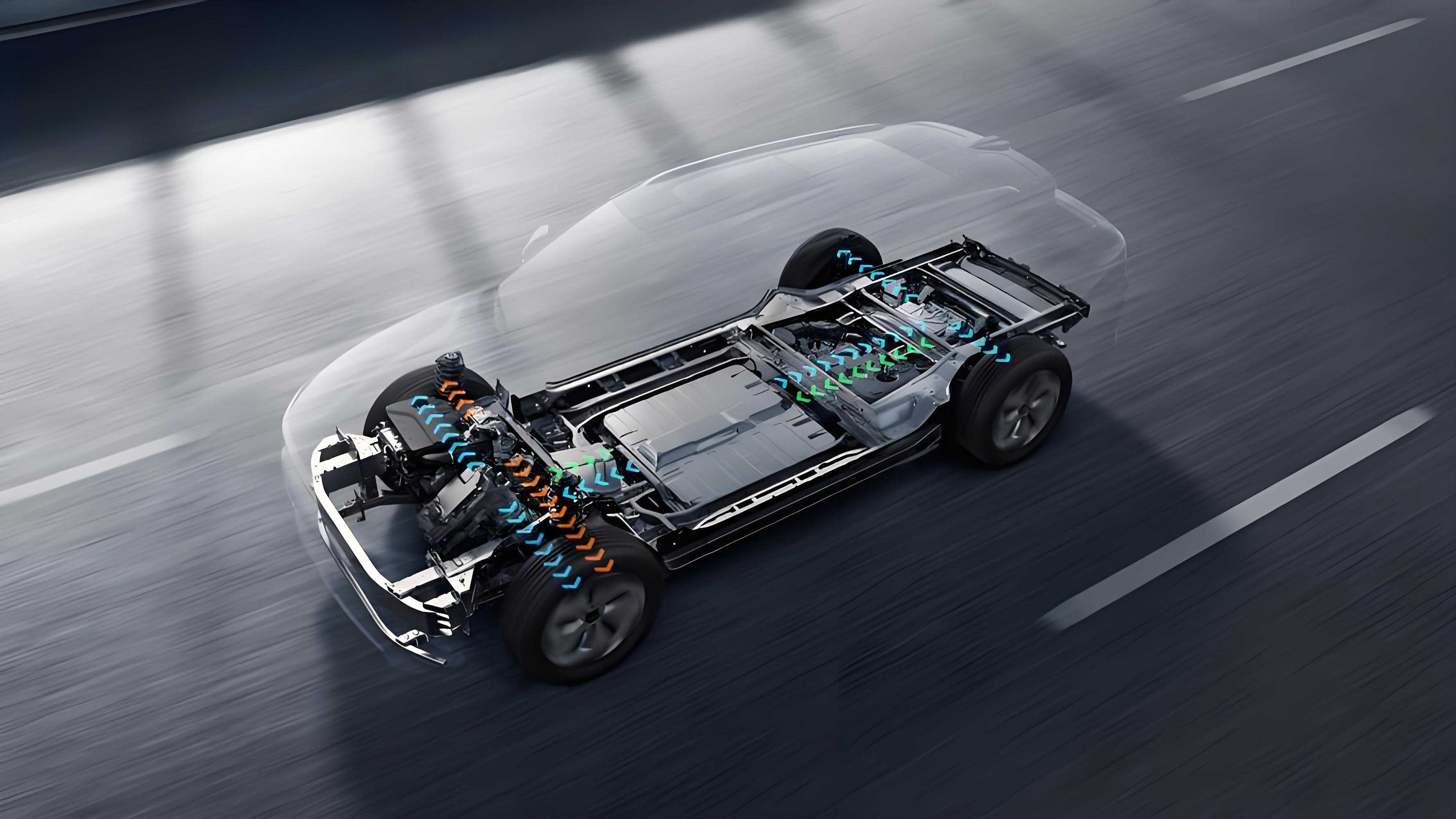
Our study utilizes a dual-motor 4WD electric vehicle configuration. Unlike internal combustion engines requiring complex transmissions, electric vehicles typically employ fixed gear ratios, enabling more direct and efficient power transfer. High-power electric motors deliver strong performance but demand sophisticated control systems to enhance safety, stability, and energy efficiency. We modeled our electric vehicle parameters, including weight distribution for optimal acceleration and transient response, based on dimensions and powertrain characteristics similar to the VW ID.4.
- Structure: Two independent permanent magnet synchronous motors (PMSM) drive the front and rear axles. Motor 2 provides the majority of the vehicle’s power.
- Parameters: Key parameters are summarized in Table 1. The vehicle mass is estimated at 250 kg, and the tire rolling radius is 0.337 m. Final drive ratios are 9.95 (front) and 11.5 (rear).
Table 1: Dual-Motor Electric Vehicle Powertrain Specifications
| Parameter | Unit | Motor 1 | Motor 2 |
|---|---|---|---|
| Rated Voltage | V | 320 | 320 |
| Rated Power | kW | 35 | 70 |
| Peak Power | kW | 80 | 150 |
| Rated Torque | Nm | 70 | 145 |
| Peak Torque | Nm | 160 | 310 |
| Rated Speed | rpm | 4,600 | 4,600 |
| Peak Speed | rpm | 13,500 | 16,000 |
| Front Final Drive | – | 9.95 | – |
| Rear Final Drive | – | – | 11.5 |
| Vehicle Mass (est.) | kg | 250 | |
| Tire Rolling Radius | m | 0.337 |
2.2 Wheel Dynamics and Slip Fundamentals
The core of ASR lies in understanding wheel dynamics and the tire-road interaction. Neglecting rolling resistance and longitudinal aerodynamic drag, the torque balance equation for a driven wheel is:
I_ω dω/dt = T_d - F_d * r (1)
where:
I_ω: Wheel rotational inertia [kg·m²]ω: Wheel angular velocity [rad/s]T_d: Drive torque applied to the wheel [Nm]F_d: Longitudinal friction force generated at the tire-road contact patch [N] (the driving force)r: Effective wheel radius [m]
The utilization adhesion coefficient μ is defined as the ratio of the longitudinal friction force F_d to the vertical load F_z on the wheel:
μ = F_d / F_z (2)
Accurate calculation of F_z, considering load transfer due to vehicle dynamics, is crucial for precise road identification. The vertical loads for each wheel (Left Front F_z,LF, Right Front F_z,RF, Left Rear F_z,LR, Right Rear F_z,RR) are:
F_z,LF = mgb/(2L) - ma_x h_g/(2L) - ma_y h_g b/(d_1 L) (3)F_z,RF = mgb/(2L) - ma_x h_g/(2L) + ma_y h_g b/(d_1 L) (4)F_z,LR = mga/(2L) + ma_x h_g/(2L) - ma_y h_g a/(d_2 L) (5)F_z,RR = mga/(2L) + ma_x h_g/(2L) + ma_y h_g a/(d_2 L) (6)
where:
m: Total vehicle mass [kg]g: Gravitational acceleration [9.81 m/s²]a: Distance from front axle to center of gravity (CG) [1.3825 m]b: Distance from rear axle to CG [1.3825 m]L: Wheelbase (a + b) [m]d_1: Front track width [1.48 m]d_2: Rear track width [1.485 m]h_g: CG height [m]a_x: Vehicle longitudinal acceleration [m/s²]a_y: Vehicle lateral acceleration [m/s²]
The longitudinal driving force F_d is limited by the available adhesion force F_φ:
F_d ≤ F_φ = μ * F_z (7)
Wheel slip occurs when F_d exceeds F_φ. The wheel slip ratio s is defined as:
s = (ωr - v_x) / (ωr) * 100% (8) (During acceleration)
where v_x is the longitudinal velocity of the wheel center (vehicle speed for non-slipping wheels). The relationship between slip ratio s and adhesion coefficient μ is fundamental. The longitudinal adhesion coefficient μ_x initially increases with s, peaks at an optimal slip ratio s_opt (point P, peak adhesion coefficient μ_p), and then decreases. At s_opt, longitudinal force is maximized. Conversely, the lateral adhesion coefficient μ_y continuously decreases as s increases for a given slip angle, reducing the tire’s ability to generate cornering force and resist skidding. The region s < s_opt is stable; s > s_opt is unstable. Different road surfaces exhibit vastly different μ_p and s_opt values (e.g., ~1.17 on dry asphalt vs. ~0.05 on ice). Therefore, accurately identifying the road surface to determine s_opt and controlling the wheel slip ratio near s_opt is crucial for maximizing traction while maintaining lateral stability in an electric vehicle.
3. Road Identification using Fuzzy Control
Accurate real-time identification of the current road surface’s maximum adhesion coefficient μ_p and optimal slip ratio s_opt is the foundation of effective ASR. While sensor-based methods offer precision, they often lack robustness and incur high costs. Model-based estimation provides a viable alternative. Our approach leverages fuzzy logic for robust and cost-effective identification.
3.1 Maximum Utilization Adhesion Coefficient Identification
The maximum utilization adhesion coefficient μ_max,u is the peak value of the μ_x vs. s curve achievable under current driving conditions. Analyzing the derivative dμ_x/ds identifies μ_max,u. During acceleration, dμ_x/ds is positive initially, becomes zero at the peak (μ_max,u), and then turns negative. Converting this to the time domain:
dμ_x/ds = (dμ_x/dt) / (ds/dt) (9)
μ_max,u is identified when dμ_x/dt transitions from positive to negative during acceleration.
3.2 Burckhardt Road Model
To establish fuzzy rules, we require standard road μ_x–s characteristics. The Burckhardt model effectively fits these curves for various surfaces:
μ(s) = c_1 * (1 - e^(-c_2 * s)) - c_3 * s (10)
where c_1, c_2, c_3 are fitting parameters specific to each road type. The optimal slip ratio s_opt and peak adhesion coefficient μ_p for the Burckhardt model are derived as:
s_opt = (1/c_2) * ln((c_1 * c_2)/c_3) (11)μ_p = c_1 - (c_3 / c_2) * (1 + ln((c_1 * c_2)/c_3)) (12)
Table 2: Burckhardt Model Parameters and Characteristics for Standard Road Surfaces
| Road Surface | c_1 | c_2 | c_3 | s_opt | μ_p |
|---|---|---|---|---|---|
| Dry Asphalt | 1.280 | 23.99 | 0.520 | 0.17 | 1.170 |
| Dry Concrete | 1.190 | 25.16 | 0.537 | 0.16 | 1.090 |
| Wet Asphalt | 0.850 | 33.82 | 0.347 | 0.13 | 0.801 |
| Cobblestone | 0.400 | 33.70 | 0.120 | 0.14 | 0.340 |
| Snow | 0.190 | 94.12 | 0.064 | 0.06 | 0.190 |
| Ice | 0.050 | 306.30 | 0.001 | 0.03 | 0.050 |
3.3 Fuzzy Logic Identification and Correction
Real-world factors like vehicle load, dynamics, and driver input introduce error between the identified μ_max,u and the true μ_p. We employ a fuzzy logic system to correct the model-based estimates of μ_p and s_opt. The system structure is shown conceptually. Inputs are:
- Identified maximum utilization adhesion coefficient (
μ_max,u) - Current actual slip ratio (
s) - Road similarity degree (a measure derived internally)
Membership functions for fuzzification are defined. A rule base (Table 3) maps these fuzzy inputs to similarity weights (x_i) for each of the 6 standard road surfaces. The outputs, corrected μ_p and s_opt, are calculated using weighted averages:
μ_p = (Σ[μ_p,i * x_i] for i=1 to 6) / (Σ x_i for i=1 to 6) (13)s_opt = (Σ[s_opt,i * x_i] for i=1 to 6) / (Σ x_i for i=1 to 6) (14)
where μ_p,i and s_opt,i are the peak coefficient and optimal slip ratio for the i-th standard road from Table 2, and x_i is the similarity weight for that road surface.
Table 3: Simplified Fuzzy Rule Base for Road Type Correction
| Rule | Input μ_max,u | Input s | Output Similarity Weight (x_i) Adjustment | |||||
|---|---|---|---|---|---|---|---|---|
| Ice | Snow | Cobble | Wet Asp | Dry Con | Dry Asp | |||
| 1 | 0.05 | Small | VH | L | L | L | L | L |
| 2 | 0.05 | Medium | H | M | L | L | L | L |
| 3 | 0.05 | Large | H | MH | L | L | L | L |
| 4 | 0.19 | Small | L | VH | L | L | L | L |
| … | … | … | … | … | … | … | … | … |
| 18 | 1.17 | Large | L | L | MH | L | L | MH |
4. Acceleration Slip Regulation (ASR) Control Strategy
4.1 ASR Activation and Deactivation Logic
The ASR system aims to maintain the driven wheel slip ratio near the identified s_opt. Control intervenes when the actual slip ratio s exceeds s_opt. The system replaces the driver-demanded torque with a calculated control torque to regulate slip. Control deactivates when the driver-demanded torque falls below the calculated ASR torque.
4.2 Sliding Mode Controller Design
We designed a robust ASR controller using Sliding Mode Control (SMC) theory. The sliding surface σ is defined as the error between the actual slip ratio and the optimal slip ratio:
σ = e = s - s_opt (15)
To drive the error e to zero, we employ an exponential reaching law:
dσ/dt = ḋ = -ε * sign(e) - k * e (16)
where ε is the switching gain (determines reaching speed) and k is the error gain. To mitigate chattering inherent in SMC, we replace the discontinuous sign() function with a continuous saturation function sat() within a boundary layer Δ:
sat(e) = { 1 if e > Δ; e/Δ if |e| ≤ Δ; -1 if e < -Δ } (17)
The modified reaching law becomes:
dσ/dt = ḋ = -ε * sat(e) - k * e (18)
Deriving the control law starts from the wheel dynamics equation (1). Solving for the drive torque T_d required to satisfy the reaching law (18) yields the SMC output torque T_SMC:
T_SMC = (I_ω r ω^2 / v_x) * s_opt + (I_ω ω v̇_x) / v_x + r F_x - (I_ω r ω^2 / v_x) * k * e - (I_ω r ω^2 / v_x) * ε * sat(e) (19)
This T_SMC is the torque command sent to the electric motors to regulate slip. The overall ASR control flow integrates road identification and SMC.
5. Simulation Results and Analysis
We rigorously evaluated the proposed ASR strategy using co-simulation between MATLAB/Simulink (control system) and CarSim (high-fidelity vehicle dynamics model). High-speed scenarios were excluded as motors operate in the constant power region with rapidly declining torque, typically keeping slip within the stable zone without ASR intervention. Focus was placed on low-medium speed scenarios critical for stability.
5.1 Straight-line Acceleration on Low-µ Surface (µ = 0.2)
Simulating acceleration from standstill on snow/ice with the accelerator pedal gradually reaching 100% and steering wheel angle fixed at 0°.
- Slip Control: The electric vehicle accurately identified the road
s_opt(error < 7%). ASR intervened multiple times as pedal position increased, rapidly controlling wheel slip to nears_opt. Motor torque output was effectively modulated. - Performance Improvement: Compared to the uncontrolled electric vehicle, ASR significantly enhanced acceleration and distance traveled within the same timeframe (48 kph vs 44 kph; 41m vs 44m after ~5 seconds), confirming improved traction and longitudinal performance.
- Crosswind Stability: At ~60 kph, a sudden 40 kph crosswind gust was applied. With ASR active, slip ratios remained near
s_opt(stable zone), resulting in minimal lateral displacement (0.05 m) and small steering correction (8°). The uncontrolled electric vehicle exhibited significant instability, nearing loss of control.
5.2 Straight-line Acceleration on Split-µ Surface (Front/Rear Change)
Simulating acceleration from standstill where the road surface changes from high-µ to low-µ (or vice-versa) under the vehicle. Accelerator pedal rapidly reached 100%; steering wheel fixed at 0°.
- Slip and Road Identification: Both front and rear wheels rapidly and accurately identified the new
s_optupon encountering the different surface, with a slight delay for the rear axle due to the vehicle’s wheelbase. - Control Effectiveness: ASR promptly intervened when slip exceeded
s_opt, effectively controlling slip near the optimal value. Control deactivated naturally when motor speed increased into the constant power region (torque falling) or driver demand was low, causing slip to drop belows_opt(seen at ~4.5 s).
5.3 Straight-line Acceleration on µ-split Surface (Left/Right Change)
Simulating acceleration where the left and right wheels transition onto surfaces with different friction coefficients. The “select-low” principle was applied: ASR controls the wheel on the low-µ side to its s_opt, limiting torque to the high-µ side wheel to maintain vehicle yaw stability. Steering wheel angle was controlled to maintain straight-line path.
- Slip Control and Yaw Stability: All four wheels identified the low-µ side
s_optas the target. On uniform surfaces, the front motor (Motor 1) torque was low, keeping front slip low. Upon encountering the split-µ surface, ASR intervened on the low-µ side, reducing torque and controlling slip tos_opt. This torque reduction also caused slip on the high-µ side to decrease further. The maximum lateral displacement (0.018 m) and steering wheel angle (16°) required to maintain straight-line travel were dramatically lower than the uncontrolled electric vehicle (-110° steering angle, 0.045 m displacement), demonstrating exceptional stability enhancement.
5.4 Lane Change on Low-µ Surface (µ = 0.2)
Simulating a lane change maneuver on snow/ice. The vehicle accelerated moderately in a straight line, then executed an acceleration lane change before decelerating.
- Slip Control During Maneuver: Initial motor torque was low, resulting in low slip ratios. During the aggressive lane change, load transfer and increased torque demand caused the left rear wheel slip to rise. ASR intervened, rapidly controlling it near
s_opt. The right rear wheel remained at low slip due to load transfer effects. - Path Tracking: With ASR active, the electric vehicle maintained sufficient lateral force to track the desired path effectively, requiring a maximum steering angle of 112° and exhibiting a maximum lateral deviation of 0.29 m. The uncontrolled electric vehicle failed to track the path, exhibiting spin-out and loss of control, highlighting the critical role of ASR in maintaining lateral stability during maneuvers on low-friction surfaces.
6. Conclusion
This research successfully developed and validated a robust ASR control strategy for dual-motor 4WD electric vehicles, integrating fuzzy logic-based road identification with sliding mode slip control. Key achievements are:
- Accurate Road Identification: A fuzzy logic system utilizing the Burckhardt model and real-time slip dynamics achieved accurate identification of the road surface’s optimal slip ratio
s_opt, with errors below 7%. - Precise Slip Control: A sliding mode controller with a boundary layer effectively regulated the wheel slip ratio to the identified
s_opt, ensuring maximum longitudinal traction while preserving lateral stability. The control demonstrated rapid response and robustness. - Significant Performance & Stability Gains: Co-simulation results across diverse low-traction scenarios proved the strategy’s effectiveness:
- Low-µ Straight: 9% higher speed and 7.4% greater distance traveled within the same time compared to uncontrolled operation.
- µ-Split Straight: Maximum lateral displacement and steering wheel angle reduced to 40% and 15% of the uncontrolled electric vehicle values, respectively.
- Low-µ Lane Change: Maintained path tracking while the uncontrolled vehicle spun out.
- Low-µ Crosswind: Minimal lateral displacement (0.05 m) and steering correction (8°) versus near loss of control without ASR.
- Dual-Motor Integration: The strategy effectively managed torque output from two independent motors, demonstrating applicability to modern electric vehicle architectures.
This ASR strategy significantly enhances the safety, performance, and stability of dual-motor electric vehicles operating on challenging low-friction surfaces. Future work involves Hardware-in-the-Loop (HIL) validation and integration with higher-level vehicle dynamics controllers.