
The relentless evolution of the electric vehicle (EV) sector and the broader push for decarbonization have placed unprecedented demands on energy storage technologies. While lithium-ion batteries with liquid electrolytes have achieved remarkable energy densities, they are approaching fundamental material limits. Furthermore, consumer anxiety regarding charging time—often termed “range anxiety”—remains a significant barrier to mass EV adoption. Fast charging (FC) technology, which aims to replenish a significant portion of battery capacity in minutes rather than hours, is thus paramount. However, in conventional liquid electrolyte systems, fast charging induces severe issues such as lithium plating on graphite anodes, electrolyte decomposition, and substantial heat generation, compromising safety, lifespan, and performance.
This context has propelled solid-state battery (SSB) technology to the forefront as the most promising successor. By replacing the flammable organic liquid electrolyte with a solid ion conductor, solid-state battery architectures promise a transformative leap: higher theoretical energy density, enhanced thermal stability, and the potential to safely utilize lithium metal anodes. Crucially, the unique properties of solid electrolytes, such as single-ion conduction and high mechanical modulus, are believed to circumvent key limitations of liquid systems, inherently enabling safer and more robust fast-charging capabilities. This article delves into the intricate challenges and sophisticated optimization strategies for realizing fast charging in solid-state battery systems, examining the interplay between materials science, electrochemistry, and interface engineering.
Fundamental Challenges for Fast Charging in Solid-State Batteries
Despite their inherent advantages, enabling practical fast charging in solid-state battery systems is fraught with multifaceted challenges that stem from the fundamental shift from liquid-to-solid interfaces and the dynamics of ion transport within rigid media.
1. Kinetic Limitations from Solid-Solid Interfaces
The most profound difference between liquid and solid systems lies in the nature of electrode-electrolyte contact. In a liquid cell, the electrolyte readily wets the porous electrode, ensuring intimate and self-healing contact at the micron and sub-micron scale. In a solid-state battery, the contact between the rigid solid electrolyte and the solid electrode particles is inherently poor. This leads to high interfacial impedance, which is the sum of charge transfer resistance and contact resistance. During fast charging, the high current density exacerbates the polarization at these interfaces, leading to a significant voltage drop that can prematurely hit charging voltage limits, thus reducing actual capacity intake. The interface is also dynamically unstable; volume changes in electrode particles during (de)lithiation can cause contact loss (“debonding”), creating locally inactive regions and increasing impedance over cycles.
2. Ionic Transport Bottlenecks
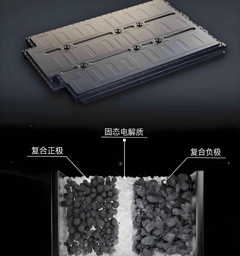
While the bulk ionic conductivity of some solid electrolytes (e.g., sulfides) rivals or exceeds that of liquid electrolytes, the overall ionic transport within a composite cathode is severely restricted. The composite cathode in a solid-state battery is a dense mixture of active material (AM), solid electrolyte (SE), and conductive carbon. Ionic percolation through this matrix is governed by the volume fraction, tortuosity ($\tau$), and connectivity of the SE phase. The effective ionic conductivity ($\sigma_{eff}$) within the composite cathode can be described by the Bruggeman relation:
$$ \sigma_{eff} = \sigma_{SE} \cdot \epsilon_{SE}^{\tau} $$
where $\sigma_{SE}$ is the bulk conductivity of the solid electrolyte and $\epsilon_{SE}$ is its volume fraction in the composite. A high tortuosity, often resulting from poor particle packing or non-ideal morphology, drastically reduces $\sigma_{eff}$. During fast charging, this leads to severe ionic concentration gradients and polarization within the cathode, limiting the usable thickness and active material loading, thereby counteracting the energy density advantage of SSBs.
3. Lithium Dendrite Propagation and Critical Current Density (CCD)
The use of lithium metal anodes is a key motivation for solid-state battery development due to its high capacity. However, during fast charging, lithium tends to deposit non-uniformly. Inhomogeneities at the Li/SE interface (e.g., surface defects, grain boundaries, or uneven pressure) create “hot spots” with locally higher current density. Lithium can preferentially plate at these sites and eventually propagate as dendrites through the solid electrolyte. The maximum current density at which a symmetric Li|SE|Li cell can be cycled without short circuit is defined as the Critical Current Density (CCD). Exceeding the CCD during charging leads to cell failure. While solid electrolytes have a higher mechanical modulus than soft separators, many still succumb to lithium filament penetration via mixed electronic-ionic conduction or creep mechanisms. Achieving a CCD high enough for practical fast-charging rates (e.g., > 3-5 mA cm⁻²) remains a core challenge.
4. Chemo-Mechanical Degradation and Heat Management
Fast charging induces rapid and large volume changes in electrode materials. In a constrained solid medium, this generates substantial internal mechanical stress. Repeated stress cycles can fracture both electrode particles and the solid electrolyte, creating new surfaces and degrading interfaces. This chemo-mechanical failure is a primary capacity fade mechanism. Additionally, while SSBs are generally safer, fast charging still generates significant heat ($Q_{gen}$) from irreversible processes:
$$ Q_{gen} = I \cdot (V – U) + I^2 \cdot R_{total} $$
where $I$ is current, $V$ is terminal voltage, $U$ is open-circuit voltage, and $R_{total}$ is total cell resistance. Poor thermal conductivity of many solid electrolytes can lead to localized overheating, accelerating interfacial side reactions and potentially inducing thermal runaway, especially if metallic lithium is present.
| Challenge Category | Liquid Electrolyte System | Solid-State Battery System | Impact on Fast Charging |
|---|---|---|---|
| Interfacial Contact | Liquid wetting, self-healing, low impedance. | Poor solid-solid contact, high and unstable impedance. | High polarization, limits usable current density, causes rapid voltage limit hit. |
| Ion Transport | Fast in bulk liquid, limited by concentration polarization. | Limited by percolation in composite cathode; single-ion conductor avoids salt concentration gradient. | Cathode ionic polarization limits thickness/loading; defines maximum practical C-rate. |
| Anode Stability | Li plating on graphite, dendrites in liquid. | Li dendrite propagation through solid electrolyte; low CCD. | Fundamental safety and cycle life limit. CCD defines upper bound for charge current. |
| Mechanical Stress | Buffered by liquid, but electrode particles may crack. | Stress concentrated at rigid interfaces; particle/SE fracture. | Causes contact loss, increases impedance, leads to rapid capacity fade during fast cycling. |
| Thermal Management | Good liquid convection, but risk of thermal runaway. | Poor solid-state heat conduction, localized hot spots. | Accelerates degradation, safety risk if heat dissipation is not managed. |
Material and Architectural Optimization Strategies
Overcoming the aforementioned challenges requires a holistic design approach targeting every component of the solid-state battery: the cathode composite, the solid electrolyte separator, the anode, and their mutual interfaces.
1. Cathode Composite Engineering
The composite cathode is often the rate-limiting component. Optimization focuses on creating a percolating network for both ions and electrons with minimal tortuosity and maximum active interface area.
a) Microstructure Design: The goal is to achieve homogeneous mixing of nano-sized active material (AM) and solid electrolyte (SE) particles. Advanced techniques like infiltration (soaking a porous AM scaffold with SE precursor) or co-sintering can create ideal bicontinuous networks. The use of dual-sized SE particles (small particles to fill voids between larger ones) can increase packing density and contact points.
b) Cathode Active Material Selection & Modification:
- Surface Coating: Coating AM particles (e.g., NCM, NCA) with a thin, ion-conductive layer (e.g., LiNbO₃, Li₂ZrO₃) reduces interfacial resistance and suppresses side reactions with the SE.
- Morphology Control: Single-crystal NCM particles, with reduced grain boundaries, exhibit less microcracking during cycling compared to polycrystalline counterparts, maintaining better contact.
- High-Rate Chemistries: Materials like LiFePO₄ (LFP) with minimal volume change (<7%) are inherently more compatible with solid-state environments. Nanostructuring LFP reduces Li⁺ diffusion path length, enabling fast kinetics despite its low electronic conductivity, which is compensated by carbon coating.
c) Homogeneous Cathode Concept: A paradigm shift involves developing single-phase materials that act as both the active material and the ion/electron conductor. For instance, materials like Li₁.₇₅Ti₂(Ge₀.₂₅P₀.₇₅S₃.₈Se₀.₂)₃ demonstrate high capacity (>250 mAh g⁻¹) and mixed ionic-electronic conductivity, eliminating the need for separate SE and carbon additives, thereby simplifying interface issues and enhancing rate capability.
2. Solid Electrolyte Development for Fast Kinetics
The ideal solid electrolyte for fast-charging solid-state battery must exhibit high ionic conductivity, low electronic conductivity, high CCD, and good deformability.
| Electrolyte Type | Examples | Ionic Conductivity (RT, S cm⁻¹) | Critical Challenges for Fast Charging | Optimization Strategies |
|---|---|---|---|---|
| Sulfide | Li₁₀GeP₂S₁₂ (LGPS), Li₆PS₅Cl (LPSCl), Li₇Si₂S₇I | 10⁻² – 10⁻³ | Air sensitivity, interfacial stability vs. oxide cathodes, moderate CCD. | Anion doping (O²⁻, Se²⁻, I⁻), cation doping (Ge, Sn), bilayer/multilayer architectures to block Li dendrites. |
| Oxide | Garnet (LLZO), Perovskite (LLTO), NASICON (LAGP) | 10⁻³ – 10⁻⁵ | High rigidity, poor interfacial contact, grain boundary resistance. | Grain boundary engineering, sintering aids, thin-film fabrication (<50 µm), introducing ductile interlayers. |
| Polymer | PEO with LiTFSI | 10⁻³ – 10⁻⁵ (at 60-80°C) | Low RT conductivity, narrow electrochemical window, mechanical softness. | Cross-linking, adding ceramic fillers (forming composite polymer electrolytes – CPEs), blending salts. |
| Halide | Li₃YCl₆, Li₃InCl₆ | 10⁻³ – 10⁻⁴ | Moisture sensitivity, compatibility with Li metal. | Developing moisture-resistant compositions, dual-halide engineering (e.g., Li₇Si₂S₇I). |
The recent discovery of dual-anion conductors like Li₇Si₂S₇I, which exhibits an ionic conductivity of ~10 mS cm⁻¹, showcases the potential of rational crystal structure design to achieve liquid-like Li⁺ transport in a solid, a prerequisite for low internal resistance during fast charging.
3. Anode Design and Stabilization
The anode side is critical for defining the CCD and safety.
a) Lithium Metal Anode Strategies:
- Interlayer Engineering: Inserting a soft, stable interlayer (e.g., Au, Al, polymer, or composite) between Li and the SE can homogenize Li-ion flux and mechanically suppress dendrite initiation.
- 3D Host Structures: Infiltrating Li into porous 3D hosts (Cu, carbon) reduces the effective current density and accommodates volume changes during plating/stripping.
- Alloy Anodes: Using Li alloys (e.g., Li-In, Li-Mg) offers higher melting points and better interfacial stability than pure Li, though at the expense of energy density.
b) Anode-Free Configuration: This ultimate design starts with a bare current collector (e.g., Cu). During the first charge, Li is plated from the cathode onto the collector. While challenging, it maximizes energy density. Success requires flawless SE/collector interface engineering and electrolytes with near-unity Coulombic efficiency to prevent dead Li accumulation during fast cycling.
c) Alternative Fast-Charging Anodes: For systems not using Li metal, materials with fast diffusion and minimal strain are key.
- Lithium Titanate (LTO): Zero-strain material with exceptional fast-charge capability but low energy density.
- Niobium-based oxides (e.g., TiNb₂O₇): Offer higher capacity than LTO with good rate performance.
- Carbon Nitrides (CₓNᵧ): Emerging 2D materials like C₃N₃ show theoretical capacities exceeding 2000 mAh g⁻¹ and promise rapid ionic transport due to their porous, layered structure, representing a promising research frontier for fast-charging solid-state battery anodes.
4. Interface Engineering
This is arguably the most critical area for enabling fast charging in solid-state battery systems. The goal is to create interfaces with low and stable impedance.
a) Cathode-SE Interface: Strategies include in-situ or ex-situ coating of AM particles, as mentioned. Additionally, using a small amount of compatible ionic liquid or polymer at the cathode interface can dramatically reduce charge-transfer resistance without compromising safety, forming a “quasi-solid” or “soft-contact” interface.
b) Anode-SE Interface: Ensuring perfect wetting of Li on the SE is crucial. This can be achieved by applying a thin layer of a more wettable material (e.g., Sn, Si) on the SE surface or by using stack pressure. The required stack pressure ($P$) to maintain contact can be related to the flow stress of Li and is a critical operational parameter for Li-metal SSBs.
c) Interfacial Impedance Modeling: The total interfacial resistance ($R_{int}$) can be modeled as a combination of charge transfer resistance ($R_{ct}$), space charge layer resistance ($R_{sc}$), and contact resistance ($R_c$):
$$ R_{int} = R_{ct} + R_{sc} + R_c $$
Engineering aims to minimize all three components through material pairing, coatings, and mechanical design.
System-Level Considerations and Future Perspectives
Translating material-level advances into a practical fast-charging solid-state battery requires system-level integration and new manufacturing paradigms.
1. Cell Architecture and Manufacturing
Thin, dense, and defect-free electrolyte layers are essential to minimize ohmic drop. Manufacturing processes like tape-casting, screen printing, or physical vapor deposition must be scaled to produce SSB cells with electrolyte thicknesses <50 µm. Bipolar stacking architectures, enabled by the solid electrolyte’s ability to act as both ion conductor and separator, can reduce inactive material and increase pack voltage for high-power charging.
2. Thermal and Pressure Management Systems
Fast-charging protocols for SSBs must be co-designed with sophisticated thermal management systems (TMS) to dissipate heat efficiently. The one-dimensional heat diffusion equation in a cell stack is:
$$ \rho C_p \frac{\partial T}{\partial t} = k \frac{\partial^2 T}{\partial x^2} + \dot{q}_{gen} $$
where $\rho$ is density, $C_p$ is heat capacity, $k$ is thermal conductivity, and $\dot{q}_{gen}$ is the volumetric heat generation rate. SSB packs may require integrated cooling plates or phase-change materials. Furthermore, for Li-metal SSBs, active pressure control systems might be necessary to maintain optimal interfacial contact throughout the cell’s life.
3. Smart Charging Algorithms
Future fast charging of solid-state battery systems will not simply apply a constant high current. Algorithms will need to adapt in real-time based on internal state estimations (ISE) for parameters like State-of-Charge (SOC), State-of-Health (SOH), and internal temperature. Models will incorporate electrochemical and thermal parameters specific to SSBs to determine the maximum safe charging current at any moment, balancing speed with longevity.
4. Future Research Directions
The path to commercialization of fast-charging SSBs will be paved by focused research:
- In-operando Diagnostics: Advanced techniques like X-ray computed tomography, neutron depth profiling, and ultrasonic sensing are needed to visualize and quantify interface evolution, Li plating, and crack formation during fast cycling.
- Multiscale Modeling: Coupling quantum calculations of interface stability with continuum-level models of stress evolution and cell performance will enable predictive design of robust systems.
- Exploration of New Chemistries: Continued search for “superionic” conductors with even higher conductivity and unprecedented CCD, as well as novel anode materials like optimized carbon nitrides or other 2D compounds, is essential.
- Recyclability and Sustainability: As SSBs develop, designing them for easy disassembly and material recovery from the outset is crucial for their long-term viability and environmental impact.
Conclusion
The pursuit of fast-charging capability is a powerful driver in the evolution of solid-state battery technology. While replacing liquid electrolytes with solids eliminates some classical fast-charging bottlenecks like concentration polarization and flammable gas generation, it introduces a new set of complex challenges centered on solid-solid interfaces, limited ionic percolation in composites, and the prevention of lithium dendrite propagation. Addressing these issues requires a concerted, multidisciplinary effort spanning the synthesis of advanced solid electrolytes with liquid-like conductivity and high critical current density, the nano-engineering of cathode composites to ensure perfect ionic and electronic percolation, the stabilization of lithium metal anodes through interfacial control, and the holistic design of cell architectures and thermal management systems. As these material and engineering hurdles are progressively overcome, the solid-state battery is poised to transcend its promise, enabling electric vehicles that recharge in minutes with enhanced safety and greater range, thereby catalyzing a true revolution in sustainable transportation and energy storage.