
The rapid evolution of energy storage technologies has positioned the solid-state battery as a pivotal candidate for next-generation applications, ranging from consumer electronics and electric vehicles to aerospace systems. The fundamental distinction of a solid-state battery lies in its replacement of the conventional flammable liquid electrolyte with a solid-state ionic conductor. This architectural shift confers significant advantages, including a higher theoretical energy density, enhanced safety by mitigating risks of leakage and thermal runaway, and potentially longer cycle life. However, the transition from liquid to solid electrolytes introduces new sets of challenges and material behaviors under various environmental stresses. Consequently, the established environmental adaptation test protocols for traditional lithium-ion batteries are often inadequate or misaligned for evaluating the robustness of solid-state battery technology. There exists a critical gap in standardized methodologies to assess how a solid-state battery performs and degrades under extreme thermal and mechanical conditions, which is essential for guaranteeing reliability in real-world applications. This work aims to bridge that gap through a comprehensive experimental investigation, proposing a foundational framework for environmental adaptation testing of solid-state batteries.
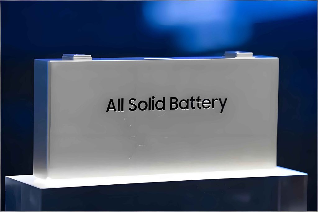
The core of our study involves a series of tailored environmental tests—high-temperature storage, low-temperature storage, drop, impact, and vibration—applied to a representative commercial-grade solid-state battery cell. We systematically analyze the post-test changes in key electrical parameters, primarily open-circuit voltage (OCV) and discharge capacity, alongside critical safety observations. Our goal is to derive scientifically justified test conditions, procedures, and pass/fail criteria that accurately reflect the unique characteristics and failure modes of a solid-state battery. This research provides the necessary empirical groundwork for future standardization efforts, ensuring that solid-state battery products can be rigorously validated for deployment in demanding environments.
Test Samples and Instrumentation
The experiments were conducted on a commercially available, pouch-type solid-state battery cell selected for its relevance to current developmental trends. The key specifications of the test sample are summarized in Table 1.
| Parameter | Specification |
|---|---|
| Nominal Capacity | ~14 Ah |
| Nominal Voltage | 3.7 V |
| Charge Cut-off Voltage | 3.85 V |
| Discharge Cut-off Voltage | 3.00 V |
| Standard Charge Current | 0.2C (≈2.8 A) |
| Standard Discharge Current | 0.2C (≈2.8 A) |
| Electrolyte Type | Solid Polymer Composite |
All tests were performed using calibrated equipment to ensure measurement traceability and accuracy. The environmental chambers (for thermal storage) and mechanical test platforms (for drop, impact, vibration) met the required specifications for control and repeatability. Electrical performance was characterized using a high-precision battery test system. The measurement accuracies were as follows: voltage and current within ±0.5%, temperature within ±0.5°C, and dimensions within ±0.1%.
High-Temperature Storage Test
Prolonged exposure to elevated temperatures is a critical stressor for any battery system. For a solid-state battery, high temperatures can accelerate interfacial degradation between the solid electrolyte and electrodes, induce creep or deformation in softer solid electrolytes, and promote parasitic side reactions despite the generally improved thermal stability.
Test Procedure: The solid-state battery was first charged to 3.85 V at a 0.2C rate under a standard ambient temperature of 25°C. After a 15-minute relaxation period, the fully charged cell was placed in a thermal chamber set at (80 ± 2)°C for a duration of 24 hours. Following this storage period, the cell was transferred to a 25°C environment to stabilize for another 24 hours. The post-storage OCV was recorded immediately. Finally, the cell was discharged at 0.2C to 3.0 V to measure its retained capacity.
Proposed Acceptance Criterion: After the high-temperature storage test, the solid-state battery must exhibit an OCV no lower than 3.6 V, and its discharge capacity must be no less than 90% of its pre-storage capacity.
Results and Analysis: The test results confirmed the relative robustness of the solid-state battery under high-temperature stress. The pre-storage capacity was measured at 13.82 Ah. After the 80°C exposure, the post-storage capacity was 13.56 Ah. The capacity retention (CR) is calculated as:
$$CR = \frac{C_{after}}{C_{initial}} \times 100\% = \frac{13.56}{13.82} \times 100\% \approx 98.1\%$$
The OCV after storage was 3.74 V, well above the 3.6 V threshold. The minor capacity loss of approximately 1.9% can be attributed to irreversible parasitic reactions at the electrode/electrolyte interface, such as the growth of a resistive interphase layer, which consumes active lithium ions. The Arrhenius equation models the temperature dependence of these degradation kinetics:
$$k = A e^{-\frac{E_a}{RT}}$$
where \(k\) is the reaction rate constant, \(A\) is the pre-exponential factor, \(E_a\) is the activation energy for the degradation reaction, \(R\) is the universal gas constant, and \(T\) is the absolute temperature. The test validates that the selected solid-state battery chemistry has a sufficiently high activation energy \(E_a\) for degradation pathways, resulting in acceptable performance retention even at 80°C.
Low-Temperature Storage Test
Low-temperature performance is often a challenge for batteries due to increased ionic resistance. In a solid-state battery, the ionic conductivity (\(\sigma\)) of the solid electrolyte typically follows a thermally activated behavior, which can lead to a dramatic drop in conductivity at sub-zero temperatures, potentially causing capacity loss and voltage polarization.
Test Procedure: The procedure mirrors the high-temperature test but with the storage condition set to (-40 ± 2)°C for 24 hours. The same pre-conditioning (0.2C charge to 3.85V at 25°C) and post-storage recovery/stabilization at 25°C were applied before measuring OCV and conducting the discharge capacity test.
Proposed Acceptance Criterion: Identical to the high-temperature test: OCV ≥ 3.6 V and capacity retention ≥ 90%.
Results and Analysis: The solid-state battery demonstrated excellent low-temperature storage capability. The initial capacity was 13.96 Ah, and the post-storage capacity was 13.82 Ah, yielding a capacity retention of:
$$CR = \frac{13.82}{13.96} \times 100\% \approx 98.9\%$$
The OCV after storage was 3.78 V. The minimal capacity loss (∼1.1%) is likely due to a temporary reduction in ionic mobility within the solid electrolyte and across interfaces at -40°C, which can trap some lithium ions in a metastable state, preventing them from contributing to the discharge cycle immediately after storage. However, upon returning to room temperature, the ionic conductivity recovers significantly, as described by the Vogel–Fulcher–Tammann or Arrhenius-type relations for ion transport:
$$\sigma(T) = \sigma_0 e^{-\frac{E_a}{k_B T}}$$
where \(\sigma_0\) is a pre-exponential factor, \(E_a\) is the activation energy for ionic conduction, and \(k_B\) is Boltzmann’s constant. The high recovery indicates that the solid electrolyte in this solid-state battery maintains sufficient morphological and interfacial stability even after deep freeze, avoiding permanent damage like delamination or crack formation that could cause irreversible capacity loss.
Mechanical Robustness Tests: Drop, Impact, and Vibration
The mechanical integrity of a solid-state battery is crucial, especially for mobile and transportation applications. While the absence of free-flowing liquid eliminates leakage hazards, the solid-solid interfaces are susceptible to debonding, and brittle ceramic solid electrolytes can fracture under shock, leading to increased internal resistance or failure.
For all three mechanical tests, a common pre-condition was used: the solid-state battery was charged to 3.85 V at 0.2C and rested for 15 minutes at 25°C. A key measured parameter was the open-circuit voltage decay before and after testing, defined as:
$$\Delta V_{oc} = \frac{V_{oc,initial} – V_{oc,after}}{V_{oc,initial}} \times 100\%$$
Proposed Acceptance Criterion for Mechanical Tests: The solid-state battery must show no evidence of leakage, fire, or explosion. Furthermore, the open-circuit voltage decay (\(\Delta V_{oc}\)) must not exceed 5%.
Drop Test
Procedure: The charged solid-state battery was dropped once from a height of (1100 ± 50) mm onto a 20 mm thick hardwood surface. The orientation of the drop was along the cell’s width (X-axis).
Results: The solid-state battery passed the test without any safety incidents (leakage, fire, explosion). The OCV decay was a negligible 0.19%, far below the 5% limit. This indicates that the internal structure, including the laminated electrodes and solid electrolyte, resisted delamination and fracture from the single high-energy impact. The kinetic energy at impact is \(E_k = m g h\), and the cell’s packaging and internal bonding effectively dissipated this energy without causing internal short circuits or significant contact loss.
Impact Test
Procedure: The charged cell was rigidly mounted on an impact test machine. It was subjected to a half-sine shock pulse with a peak acceleration of (392.0 ± 4.0) m/s² (approximately 40g) and a pulse duration of 6 ms. This test was applied in three mutually perpendicular axes, with two shocks in each direction (positive and negative), for a total of 12 shocks.
Results: The solid-state battery withstood the repeated high-G shocks safely. The measured OCV decay was only 0.11%. This excellent performance underscores the mechanical stability of the cell’s internal stack. The force experienced during impact can be approximated by \(F = m \cdot a_{peak}\). The solid-state battery’s construction successfully transmitted and withstood these inertial forces without compromising the ionic conduction paths.
Vibration Test
Procedure: The charged cell was rigidly fastened to a vibration table. It was subjected to sinusoidal vibration with an amplitude of 0.76 mm (1.52 mm double amplitude). The frequency was swept logarithmically from 10 Hz to 55 Hz and back to 10 Hz over approximately one minute per sweep. The solid-state battery was tested along three orthogonal axes, with 90-100 minutes of vibration per axis, totaling 270-300 minutes.
Results: No safety issues occurred during or after the extended vibration test. The OCV decay was 0.21%. Vibration tests are designed to simulate long-term transportation or operational environments that can cause fatigue failure. The low voltage decay confirms that the solid-state battery’s components (electrodes, solid electrolyte, current collectors) did not experience fretting, fatigue cracking, or contact loss that would significantly increase internal resistance.
Comprehensive Analysis and Proposed Standard Test Method
The collective results from this experimental campaign are summarized in Table 2. They paint a picture of a robust solid-state battery technology with exceptional environmental adaptation, particularly in terms of voltage stability and safety under mechanical abuse.
| Test | Condition | Key Result (OCV) | Key Result (Capacity Retention) | Safety Observation | Pass/Fail |
|---|---|---|---|---|---|
| High-Temp Storage | 80°C for 24h | 3.74 V (≥3.6 V) | 98.1% (≥90%) | N/A | Pass |
| Low-Temp Storage | -40°C for 24h | 3.78 V (≥3.6 V) | 98.9% (≥90%) | N/A | Pass |
| Drop | 1.1m height, 1 hit | ΔVoc = 0.19% (≤5%) | N/A | No leak/fire/explosion | Pass |
| Impact | 40g, 6ms, 12 shocks | ΔVoc = 0.11% (≤5%) | N/A | No leak/fire/explosion | Pass |
| Vibration | 10-55 Hz, ~300 min | ΔVoc = 0.21% (≤5%) | N/A | No leak/fire/explosion | Pass |
Based on this analysis, we propose the following generalized test method framework for the environmental adaptation assessment of solid-state batteries. This framework can serve as a template for product specifications and future standards.
Draft Standard Test Method for Solid-State Battery Environmental Adaptation
1. Scope: This method defines test procedures to evaluate the environmental adaptation of solid-state battery cells, including high-temperature storage, low-temperature storage, drop, impact, and vibration tests.
2. Test Conditions: All tests, unless otherwise specified, shall be conducted in an environment with temperature between 15°C and 35°C, relative humidity between 20% and 80%, and atmospheric pressure between 86 kPa and 106 kPa.
3. Test Procedures and Requirements:
| Test Item | Procedure | Requirements |
|---|---|---|
| High-Temperature Storage | 1. Charge cell to its specified charge cut-off voltage (e.g., 3.85V) at 0.2C rate at 25°C. 2. Store cell at (80±2)°C for 24 hours. 3. Stabilize at 25°C for 24 hours. 4. Measure OCV and discharge capacity at 0.2C to specified cut-off voltage. |
1. OCV after test ≥ [Specified Min. Voltage, e.g., 3.6V]. 2. Discharge capacity ≥ 90% of pre-storage capacity. |
| Low-Temperature Storage | 1. Charge cell to its specified charge cut-off voltage at 0.2C rate at 25°C. 2. Store cell at (-40±2)°C for 24 hours. 3. Stabilize at 25°C for 24 hours. 4. Measure OCV and discharge capacity at 0.2C to specified cut-off voltage. |
1. OCV after test ≥ [Specified Min. Voltage, e.g., 3.6V]. 2. Discharge capacity ≥ 90% of pre-storage capacity. |
| Drop Test | 1. Charge cell to its specified charge cut-off voltage at 0.2C rate. 2. Drop cell from (1100±50) mm height onto 20 mm hardwood board once along a specified axis. 3. Measure OCV after test. |
1. No leakage, fire, or explosion. 2. OCV decay (ΔVoc) ≤ 5%. |
| Impact Test | 1. Charge cell to its specified charge cut-off voltage at 0.2C rate. 2. Mount rigidly on shock machine. 3. Apply half-sine shock: (392±4) m/s², 6 ms duration. 4. Apply 2 shocks per direction along 3 orthogonal axes (12 total). 5. Measure OCV after test. |
1. No leakage, fire, or explosion. 2. OCV decay (ΔVoc) ≤ 5%. |
| Vibration Test | 1. Charge cell to its specified charge cut-off voltage at 0.2C rate. 2. Mount rigidly on vibration table. 3. Apply sinusoidal vibration: 0.76 mm amplitude, frequency sweep 10-55-10 Hz (1 min/sweep). 4. Test for 90-100 min per axis (3 axes). 5. Measure OCV after test. |
1. No leakage, fire, or explosion. 2. OCV decay (ΔVoc) ≤ 5%. |
Conclusion and Application Outlook
This research has systematically addressed the critical need for environmental adaptation test methods tailored to solid-state battery technology. Through empirical testing and analysis, we have demonstrated that the solid-state battery possesses excellent stability under extreme thermal storage conditions and remarkable mechanical robustness against drop, impact, and vibration stresses. The proposed test methods and quantitative criteria—such as the 90% capacity retention limit for thermal storage and the 5% OCV decay limit for mechanical tests—provide a practical and technically sound framework for quality assurance and reliability screening.
The methodology developed here has already been implemented in the drafting of internal product specifications and test reports for several research and industrial entities, facilitating the development and qualification of solid-state battery products. It establishes a common language and a set of benchmarks for evaluating one of the most promising aspects of a solid-state battery: its inherent durability. Future work will involve expanding this framework to include other environmental factors like thermal cycling, humidity exposure, and more complex combined stresses, as well as adapting the criteria for different form factors and chemisties within the broad family of solid-state batteries. The continuous refinement of such test standards is essential to guide the maturation of solid-state battery technology from the laboratory to widespread commercial and industrial deployment.