
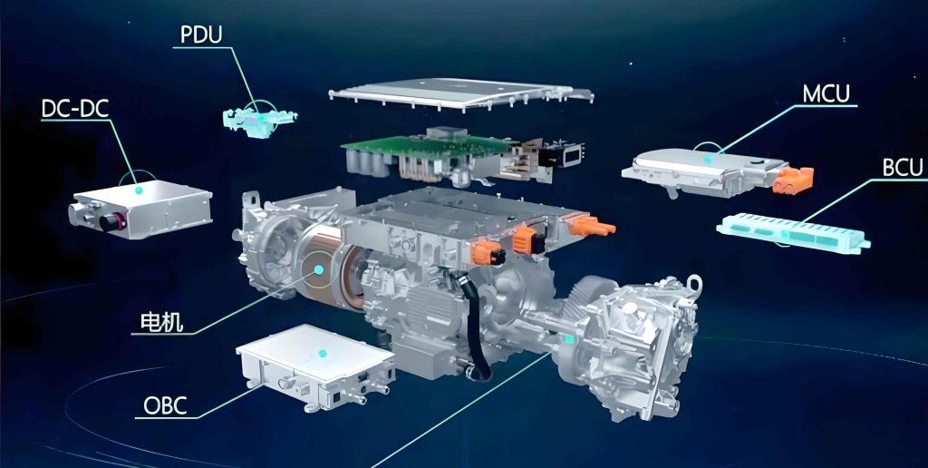
In modern electric vehicles, the transition from traditional internal combustion engines to high-voltage electric drive systems has introduced significant challenges in electromagnetic compatibility (EMC). The electric drive system, which serves as the primary power source, utilizes power switching devices with high dv/dt and di/dt characteristics. These devices are prone to generating high-amplitude, broadband electromagnetic interference (EMI), which can adversely affect safety systems, intelligent controls, and other sensitive equipment within the vehicle, thereby posing risks to safe operation. Compared to discrete electric drive systems, the multi-in-one electric drive system (AEDS) features higher integration of components, more complex inter-system coupling, and the replacement of long three-phase AC cables with busbars. Additionally, the AEDS is often housed within the motor casing, altering its EMI characteristics. These changes necessitate precise modeling of busbar parameters and eliminate the need for separate EMI analysis on the AC side. This article presents a comprehensive, module-based modeling approach to predict conducted emissions in AEDS, with a focus on the impact of parasitic parameters.
The foundation of accurate EMI prediction lies in the detailed modeling of each component within the electric drive system. I adopt a modular approach, where individual parts such as the IGBT, DC shielded cables, three-phase AC busbars, permanent magnet synchronous motor (PMSM), and filter circuits are modeled separately and then integrated into a complete simulation model. This method ensures that the high-frequency behavior of the electric drive system is captured effectively, enabling risk assessment and mitigation strategies for conducted emissions.
Modular Modeling of the Electric Drive System
The electric drive system comprises several key modules, each contributing to the overall EMI profile. Below, I describe the modeling techniques for each module.
IGBT Dynamic Characteristics Modeling
The IGBT is a primary noise source in the electric drive system due to its switching actions. Traditional modeling methods include measurement-based and simulation-based approaches, but each has limitations. Measurement-based models offer high accuracy but require difficult-to-obtain inputs, while simulation-based models are easier to construct but less precise. To address this, I employ a hybrid “Datasheet+DPT” method, which combines parameters from the IGBT datasheet with data from double-pulse tests (DPT). DPT is a standard procedure for characterizing IGBT performance, providing critical parameters such as turn-on time ($t_{on}$), turn-off time ($t_{off}$), turn-on energy ($E_{on}$), and turn-off energy ($E_{off}$). For an IGBT model FS820R08A6P2B operating at 8 kHz with a DC voltage of 365 V, the equivalent circuit model includes external port parameters as summarized in Table 1.
| Parameter | Value |
|---|---|
| $R_g$ | 6.98 Ω |
| $R_c$ | 23 μΩ |
| $R_e$ | 23 μΩ |
| $C_{cg}$ | 34 pF |
| $C_{ce}$ | 16 nF |
| $L_g$ | 4.0 nH |
| $L_c$ | 3.8 nH |
| $L_e$ | 0.2 nH |
| $C_{ge}$ | 47 nF |
The dynamic characteristics are validated by comparing simulation waveforms with实测 data, showing high consistency. This hybrid modeling approach enhances the accuracy of the electric drive system simulation.
Modeling of DC Shielded Cables and Three-Phase AC Busbars
DC shielded cables and three-phase AC busbars act as energy transmission hubs in the electric drive system, and their high-frequency parasitic parameters significantly influence EMI propagation. Using datasheet specifications, I construct 3D models of these components and extract resistance, inductance, and capacitance (RLC) parameters via electromagnetic field simulation software. The equivalent circuits for the three-phase AC busbars and DC shielded cables are derived, with key parameters listed in Table 2 and Table 3, respectively.
| Parameter | Value |
|---|---|
| $L_{UU}$ | 97.7 nH |
| $L_{VV}$ | 93.0 nH |
| $L_{WW}$ | 97.7 nH |
| $L_{UV}$ | 19.8 nH |
| $L_{UW}$ | 9.32 nH |
| $L_{VW}$ | 19.8 nH |
| $C_{UU}$ | 1.7 pF |
| $C_{VV}$ | 1.7 pF |
| $C_{WW}$ | 1.7 pF |
| $C_{UV}$ | 1.8 pF |
| $C_{VW}$ | 1.8 pF |
| $C_{UW}$ | 0.38 pF |
| $R_{UU}$ | 20.0 mΩ |
| $R_{VV}$ | 20.5 mΩ |
| $R_{WW}$ | 20.2 mΩ |
| Parameter | Value |
|---|---|
| $L_{copper1}$ | 1285.2 nH |
| $L_{shield1}$ | 1229.4 nH |
| $L_{copper2}$ | 1285.2 nH |
| $L_{shield2}$ | 1229.4 nH |
| $L_{cs1}$ | 1229.4 nH |
| $L_{ss}$ | 722.4 nH |
| $L_{cs2}$ | 1229.4 nH |
| $L_{sc1}$ | 723.0 nH |
| $L_{cc}$ | 113.2 nH |
| $L_{sc2}$ | 723.0 nH |
| $C_{cs1}$ | 1540.2 pF |
| $C_{cs2}$ | 1540.2 pF |
| $C_{ss}$ | 24.6 pF |
| $R_{c1}$ | 1008.0 mΩ |
| $R_{s1}$ | 588.0 mΩ |
| $R_{c2}$ | 888.0 mΩ |
| $R_{s2}$ | 384.0 mΩ |
These parameters are essential for representing the distributed nature of the cables and busbars in the electric drive system, affecting both common-mode and differential-mode interference paths.
PMSM Impedance Modeling
The PMSM in the electric drive system exhibits parasitic capacitances and inductances that provide additional paths for EMI at high frequencies. To model this, I consider both common-mode and differential-mode impedance circuits. The motor’s star-connected equivalent model includes single-phase common-mode impedance ($Z_{cm}$) and single-phase differential-mode impedance ($Z_{dm}$). These cannot be measured directly; instead, they are derived from port measurements of common-mode impedance ($Z_{CM}$) and differential-mode impedance ($Z_{DM}$) using the following conversion formulas:
$$Z_{CM} = \frac{Z_{cm} Z_{dm} + 2Z_{cm}^2}{Z_{cm} + 3Z_{dm}}$$
$$Z_{DM} = \frac{3Z_{cm} Z_{dm}}{2Z_{cm} + 2Z_{dm}}$$
Solving these equations yields expressions for $Z_{cm}$ and $Z_{dm}$:
$$Z_{cm} = 3Z_{CM} + \sqrt{9Z_{CM}^2 – 2Z_{CM}Z_{DM}}$$
$$Z_{dm} = \frac{2Z_{CM}Z_{DM}}{9Z_{CM} – 2Z_{DM}}$$
Based on resonance points in the impedance curves, an RLC network is constructed to represent the motor’s high-frequency behavior. Simulation results align well with calculated impedance curves, confirming the model’s accuracy for the electric drive system.
Filter Circuit Design
To suppress conducted interference on the power lines, a π-type filter is integrated into the electric drive system. The ideal filter consists of a 65 μH iron-based nanocrystalline core ($L_r$) and two Y-capacitors ($C_{Y1}$ = 220 nF, $C_{Y2}$ = 100 nF). However, at high frequencies, parasitic elements must be considered. The impedance of the magnetic core and Y-capacitors is modeled using vector fitting based on measured data, resulting in equivalent circuits that capture their frequency-dependent characteristics. The complete filter model includes parasitic inductances and resistances, as shown in the equivalent circuit diagram. This detailed representation ensures that the filter’s performance in the electric drive system is accurately simulated across the conducted emission frequency range of 150 kHz to 30 MHz.
Complete Conducted Emission Simulation Model for the Electric Drive System
After individually modeling and validating each module, I integrate them into a full conducted emission simulation model of the electric drive system. The model includes the battery pack, IGBTs, DC shielded cables, three-phase AC busbars, PMSM, and filter circuit, all connected according to the system schematic. Line impedance stabilization networks (LISNs) are placed at the positive and negative terminals to simulate the standard test setup, with the voltage across the 50 Ω loads equivalent to the measured conducted emission voltage in实际 tests. This comprehensive model allows for预测 of EMI risks and evaluation of mitigation strategies in the electric drive system.
Comparison Between Simulation and Test Results for the Electric Drive System
To validate the simulation model, I conduct conducted emission tests on a physical AEDS setup in an anechoic chamber. The test platform includes the electric drive system, LISNs, and an EMI receiver. The simulated voltage spectrum from the positive LISN port is compared with实测 data over the frequency range of 150 kHz to 30 MHz. The results show high consistency in trends, with resonant peaks at key frequencies such as 420 kHz, 1.6 MHz, 2.5 MHz, 4.5 MHz, 7.8 MHz, 13.6 MHz, and 17 MHz aligning closely between simulation and test. However, some discrepancies in amplitude are observed, primarily due to differences in signal processing methods (simulation uses Fourier transform while tests employ point-frequency scanning with an EMI receiver) and the absence of low-voltage control signals in the simulation. Despite these minor deviations, the model effectively predicts the EMI behavior of the electric drive system, demonstrating its utility for risk assessment.
Analysis of Parasitic Parameter Effects on Conducted Emissions in the Electric Drive System
Parasitic parameters play a crucial role in high-frequency EMI in the electric drive system, influencing noise amplitude and propagation paths. I investigate three key parasitic elements using controlled variable simulations to understand their impact on conducted emissions.
Effect of Y-Capacitor Parasitic Inductance
The parasitic inductance ($L_{yb}$) of the Y-capacitor near the noise source (i.e., $C_{Y2}$ in the filter) affects its impedance characteristics. For a 220 nF Y-capacitor, the impedance magnitude varies with frequency and $L_{yb}$. The impedance $Z_{Y}$ as a function of angular frequency $\omega$ and $L_{yb}$ can be expressed as:
$$Z_{Y} = \sqrt{R_{Y}^2 + \left(\omega L_{yb} – \frac{1}{\omega C_{Y}}\right)^2}$$
where $R_{Y}$ is the equivalent series resistance. Simulation results for different $L_{yb}$ values (5 nH, 50 nH, and 500 nH) reveal that at lower frequencies, larger $L_{yb}$ reduces conducted noise voltage, while at higher frequencies, smaller $L_{yb}$ is beneficial. This is because the Y-capacitor’s impedance determines the分流 of interference current to ground. Optimizing $L_{yb}$ based on critical frequency bands can significantly reduce EMI in the electric drive system.
Effect of Distribution Capacitance Between IGBT and Heat Sink
The distribution capacitance ($C_p$) between the IGBT module and the heat sink provides an additional common-mode path. At low frequencies, $C_p$ has high impedance, but at high frequencies, its impedance decreases, allowing more common-mode current to flow. The impact on conducted emissions is analyzed by varying $C_p$ from 8 pF to 800 pF. The common-mode impedance due to $C_p$ is given by:
$$Z_{p} = \frac{1}{j\omega C_p}$$
Simulation results indicate that for frequencies below 7 MHz, larger $C_p$ reduces noise voltage, but above 7 MHz, larger $C_p$ increases noise. This suggests that minimizing $C_p$ through design measures, such as adding shielding layers, can suppress high-frequency EMI in the electric drive system.
Effect of Film Capacitor Parasitic Inductance
The film capacitor, used for voltage stabilization and filtering in the electric drive system, has parasitic inductance ($L_m$) that influences its high-frequency impedance. The impedance of the film capacitor is:
$$Z_{m} = j\omega L_m + \frac{1}{j\omega C_m}$$
where $C_m$ is the capacitance. Simulations with varying $L_m$ show that while resonant frequencies remain unchanged, larger $L_m$ increases noise voltage in the 5–30 MHz range. This highlights the importance of designing film capacitors with low parasitic inductance to mitigate conducted emissions in the electric drive system.
Conclusion
The integrated simulation model developed for the multi-in-one electric drive system provides an effective tool for predicting conducted electromagnetic interference risks. By employing a modular modeling approach that includes precise representations of IGBT dynamics, cable and busbar parasitics, motor impedance, and filter circuits, the model achieves high agreement with实测 data. The analysis of parasitic parameters underscores their significance in EMI behavior, offering insights for optimizing component design and suppression strategies. This methodology is applicable to various electric drive systems, enhancing their EMC performance. Future work will extend the model to incorporate low-voltage systems like onboard chargers and DC-DC converters, addressing cross-coupling effects in the overall vehicle electric drive system.