
The relentless advancement of the new energy vehicle (NEV) industry has placed the electric drive system at the forefront of technological development. As a cornerstone of vehicle propulsion, the performance and reliability of the electric drive system are paramount. Among its many critical attributes, Electromagnetic Compatibility (EMC) stands out as a particularly challenging and essential discipline. The electric drive system is a significant source of electromagnetic emissions due to the high-voltage, high-frequency switching of its power electronics (e.g., IGBTs, SiC MOSFETs), and it is also highly susceptible to interference, given its direct role in vehicle safety and motion control. Failures induced by electromagnetic disturbances can have severe consequences. Consequently, the electromagnetic emissions (EMI) and immunity (EMS) characteristics of the electric drive system are subjected to some of the most stringent requirements in the automotive EMC landscape.
Traditionally, EMC development for automotive components followed a component-to-vehicle validation path. However, the complexity and integration level of modern electric drive systems necessitate a more nuanced approach. This article explores the development trajectory of EMC testing for electric drive systems, analyzing the evolution of standards, test methodologies, and bench setups. It further delves into emerging trends, including the testing of integrated powertrains, multi-motor systems, and the shift towards system-level and transient condition evaluations.
1. The EMC Landscape for Electric Drive Systems: Standards and Frameworks
The foundation of any rigorous test regime lies in its standards. For the electric drive system, the standardization landscape has evolved from generic component rules to more specific, albeit still developing, guidelines.
1.1 International Standards Overview
Globally, no single standard is dedicated exclusively to the EMC of electric drive systems. Instead, testing typically falls under the umbrella of broader automotive EMC standards.
- CISPR 25: This standard, “Vehicles, boats and internal combustion engines – Radio disturbance characteristics – Limits and methods of measurement for the protection of on-board receivers,” is the primary reference for component-level emissions testing. The fourth edition (2016) introduced considerations for high-voltage components and included an informative annex (Figure I.10) depicting a test setup for an electric drive system with a loaded motor. However, it lacks detailed prescriptions for operating conditions (duty cycle), grounding schemes, and mechanical fixtures. The recently published fifth edition has not substantially changed this approach.
- ECE R10: The United Nations Economic Commission for Europe (UNECE) Regulation No. 10 is a mandatory type-approval standard for vehicles concerning EMC. Its latest revisions (e.g., 6th and 7th series of amendments) provide a comprehensive framework covering emissions, immunity, and transient phenomena. Electric drive systems are generally tested as high-voltage DC-supplied components according to the methods outlined in Annex 4 (Narrowband Emissions) and Annex 5 (Broadband Emissions) of the regulation, although specific dynamometer-based test procedures are not explicitly detailed.
- ISO Standards: A suite of ISO standards addresses specific phenomena: ISO 7637 (transients along supply lines), ISO 11452 (component immunity to radiated and conducted disturbances), and ISO 10605 (electrostatic discharge). These are often applied to the electric drive system controller and its low-voltage sections.
1.2 Domestic Standards in China
China has been proactive in developing standards tailored to its rapidly growing NEV market. While many standards are adaptations of international ones (e.g., GB/T 18655 is aligned with CISPR 25), two are particularly relevant:
- GB/T 18488 (Electric drive motor system for electric vehicles): This standard covers a wide range of tests for drive motor systems, including EMC. Its earlier versions referenced general vehicle standards. The 2015 edition states that radiated emission and immunity tests should be conducted “according to the test method provided by the manufacturer or the customer,” highlighting the lack of a definitive method at the time. The standard is currently under its third revision, with EMC methods and limits being a key discussion point.
- GB/T 36282-2018 (EMC requirements and test methods for electric drive system of electric vehicles): This is a landmark standard specifically for electric drive system EMC. It provides clear requirements for both emissions and immunity tests. Crucially, it defines a standard operating condition: the electric drive system should operate at 50% of rated speed and 50% of rated torque, achieving a mechanical output of 25% of its continuous power. This represents a typical vehicle operating point. The standard also offers more detailed guidance on test layout compared to its international counterparts, making it a vital reference for laboratories and manufacturers in China.
The table below summarizes the key standards applicable to electric drive system EMC testing.
| Standard | Scope / Focus | Relevance to Electric Drive System | Status/Notes |
|---|---|---|---|
| CISPR 25 | Component emissions for receiver protection | Primary emissions standard; includes example setup for loaded motor. | Informative guidance only; lacks detailed test conditions. |
| ECE R10 | Whole-vehicle and component EMC type-approval | Treats electric drive system as a DC-supplied component for emissions/immunity. | Mandatory for EU market; comprehensive but not specific to dyno testing. |
| ISO 11452 / 7637 / 10605 | Component immunity, conducted transients, ESD | Applied to the control unit and low-voltage ports of the electric drive system. | Widely used for design validation. |
| GB/T 36282-2018 | EMC of electric drive systems | Dedicated national standard; specifies test conditions (50% speed, 50% torque, 25% power) and layout. | Critical reference for the Chinese market; provides much-needed specificity. |
| GB/T 18488.2 (under revision) | Drive motor system performance | Includes EMC as part of a broader test suite. Methodology was historically undefined. | Under revision; expected to align more closely with dedicated EMC practices. |
2. Evolution of EMC Test Technologies for Electric Drive Systems
The core challenge in testing an electric drive system lies in replicating its real-world operational state—under mechanical load—within the controlled environment of an EMC laboratory (e.g., a semi-anechoic chamber). This has driven significant innovation in test bench architectures.
2.1 Test Bench Architectures: From Passive to Active Loading
The fundamental goal is to couple a dynamometer to the electric drive system’s output shaft to apply a controlled load. Several architectural solutions have emerged:
- Through-the-Wall Shaft Active Bench: This is the most prevalent and capable setup for design validation. The dynamometer is located outside the chamber, with its shaft penetrating the chamber wall via a waveguide to connect to the electric drive system inside. This arrangement allows for high-speed, high-torque operation with excellent control precision. It closely mimics the vehicle’s operational mode, where the electric drive system provides motive torque. The high cost of the dynamometer and chamber modification is its main drawback.
- Mobile Active Bench: Here, a compact dynamometer is placed inside the chamber alongside the electric drive system. This offers flexibility and avoids complex wall penetrations but is often limited in maximum power (high speed or high torque, but not both simultaneously) due to size and cooling constraints.
- Passive Loading Bench: A lower-cost alternative uses a passive load, such as a brake or a water vortex, to absorb power. While suitable for basic emissions摸底 testing (pre-compliance), it offers poor control over speed and torque and cannot simulate all operational profiles accurately.
- Inductive Load Simulation: Some laboratories, focusing on the inverter as the primary noise source, replace the physical motor with a three-phase inductive load bank. This simplifies the setup but ignores the influence of the actual motor’s parasitic characteristics, bearing currents, and the mechanical system on EMC performance.
The choice of bench significantly impacts the test results and their correlation to vehicle-level performance. Mitigating shaft-induced currents (common-mode currents flowing through bearings) is a common challenge across all setups, often addressed using insulated shafts or shaft grounding brushes.
| Bench Type | Power Capability | Control Precision | Relative Cost | Typical Use Case |
|---|---|---|---|---|
| Through-the-Wall Active | High Speed, High Torque | Very High | High | Design Verification, Type-Approval Support |
| Mobile Active | Medium/High Speed, Medium Torque | High | Medium-High | Design Verification, R&D Testing |
| Passive Loading | Low Speed, Low Torque | Low | Low | Pre-compliance, R&D Troubleshooting |
| Inductive Load | N/A (Electrical only) | N/A (Steady electrical load) | Low | Inverter-focused Emissions Analysis |
2.2 The Impact of Integration on EMC Characteristics
The technology of the electric drive system itself has evolved, directly impacting its EMC signature. The trend is moving decisively from discrete systems (separate motor, inverter, gearbox) to highly integrated multi-in-one or integrated powertrain systems.
- Discrete Systems: The inverter connects to the motor via long three-phase AC cables. These cables act as efficient antennas for both differential-mode and common-mode noise. Gaps and openings in separate housings for connectors and cooling reduce shielding effectiveness.
- Integrated Powertrain (eAxle): The motor, inverter, and reducer are housed in a single, compact casing. This eliminates the lengthy three-phase cables, replaces them with very short busbars or direct connections, and results in a more sealed metallic enclosure with fewer apertures. The shielding effectiveness $$SE(dB) = 10 \log_{10}\left(\frac{P_i}{P_t}\right)$$ (where \(P_i\) is incident power and \(P_t\) is transmitted power) of such a structure is inherently higher. Consequently, integrated electric drive systems generally demonstrate superior radiated emissions performance compared to their discrete predecessors.
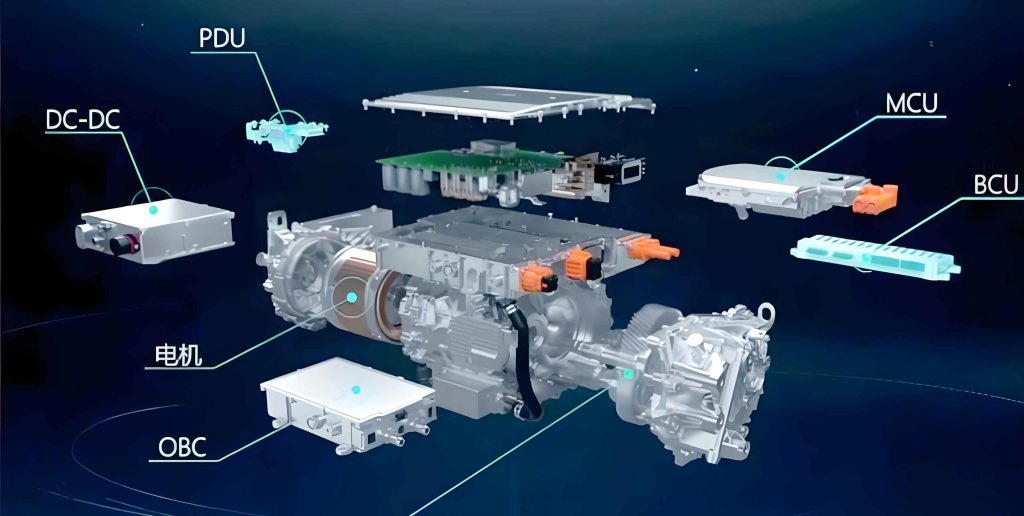
- Multi-in-One Controllers: The integration extends beyond the powertrain. “N-in-One” controllers combine the inverter with other power electronics like the DC-DC converter, onboard charger (OBC), and auxiliary power modules. While saving space and cost, this concentrates multiple noise sources (switching at different frequencies) within one enclosure, increasing the risk of internal crosstalk and creating a more complex electromagnetic environment to manage.
The fundamental emissions from the power stage can be modeled by considering the switching voltage slew rate (dv/dt) and the parasitic network. The spectral envelope of the switching noise can be approximated, with harmonics occurring at multiples of the switching frequency \(f_{sw}\):
$$V_{emi}(f) \propto V_{dc} \cdot \frac{\sin(\pi f / f_{sw})}{\pi f / f_{sw}} \cdot \frac{1}{\sqrt{1 + (f / f_{p})^2}}$$
where \(V_{dc}\) is the DC-link voltage and \(f_{p}\) is the dominant pole frequency determined by parasitic capacitances and inductances in the loop. Integration changes the parasitic network (\(f_{p}\)), often for the better by reducing stray inductance.
3. Emerging Trends in Electric Drive System EMC Evaluation
As vehicle architectures become more complex, EMC test methodologies must adapt. The future of electric drive system testing involves addressing new configurations and moving beyond steady-state evaluations.
3.1 Testing Integrated eAxle Systems
Testing a fully integrated electric drive system with a differential and two output half-shafts presents a mechanical challenge. The common method of welding one differential output to create a single shaft input for a dynamometer can induce mechanical resonances and stress, potentially affecting EMC measurements. The industry is moving towards dedicated eAxle test benches that can accommodate the native output configuration.
An advanced setup involves using two “through-the-wall” dynamometers, connected via original vehicle half-shafts to both outputs of the electric drive system. This allows symmetric loading, accurately replicating the real mechanical interface and load paths. This configuration also enables testing from multiple aspects (e.g., front and side of the unit) within a 3-meter or 10-meter chamber, providing a more complete radiated profile assessment.
2 Testing Dual-Motor and Range-Extender Systems
Dual-motor configurations, common in high-performance AWD EVs or range-extender hybrids, present a new challenge. One motor may be dedicated to driving, while another may function primarily as a generator. Traditional single-axis benches cannot test both units simultaneously under load.
The solution lies in a hybrid bench approach. A primary through-the-wall dynamometer can be used to motor the generating electric drive system (simulating the engine load), while a mobile dynamometer inside the chamber can apply a load to the driving electric drive system. A bi-directional DC power supply (battery emulator) provides the high-voltage bus and absorbs regenerated power. This setup can create realistic scenarios where one unit is motoring and the other is generating simultaneously.
The combined EMI signature \(EMI_{total}(f)\) of such a dual system is not merely additive but involves complex coupling:
$$EMI_{total}(f) = \sqrt{|EMI_{drive}(f)|^2 + |EMI_{gen}(f)|^2 + 2\Gamma(f)\cdot|EMI_{drive}(f)|\cdot|EMI_{gen}(f)|}$$
where \(\Gamma(f)\) is a frequency-dependent coupling coefficient between the two subsystems, influenced by shared grounds, DC-link impedance, and physical layout.
| System Configuration | EMC Test Challenge | Proposed Advanced Test Solution | Key Simulated Condition |
|---|---|---|---|
| Integrated eAxle (Two Outputs) | Mechanical coupling to dyno; asymmetric loading. | Dual dynamometers connected via original half-shafts. | Realistic mechanical interface and load distribution. |
| Dual-Motor (Drive + Generate) | Simultaneous loaded operation of two units. | Hybrid bench: through-wall dyno + mobile dyno + bi-directional power supply. | Concurrent motoring and generating modes with power flow. |
| Multi-in-One Controller | Interference between co-located power stages (OBC, DCDC, Inverter). | System-level testing with all subsystems active and communicating. | Crosstalk and conducted disturbances on shared internal buses. |
3.3 Transient and Dynamic Operating Condition Testing
Current EMC standards predominantly specify tests under steady-state conditions (e.g., constant speed and torque). However, real-world driving involves constant transients—hard acceleration, regenerative braking, and torque vectoring. These transients can excite different resonant modes in the power electronics and cause peak emissions that are not captured in steady-state tests. Observations show that broadband noise levels, particularly in sensitive bands like FM radio (88-108 MHz), can increase significantly during acceleration events compared to constant-speed cruising.
Future test platforms require dynamometers and control systems capable of executing dynamic speed/torque profiles while EMC measurements are taken. This involves synchronized control where the dynamometer follows a profile defined by the electric drive system’s CAN commands (using tools like CANalyzer with DBC files) or a predefined vehicle cycle. The data acquisition for emissions must also adapt, using spectrum analyzers in Max Hold, Average, or even time-domain scan modes correlated with the operating point.
The dynamic current during a torque transient can be modeled as:
$$i_{q}(t) = I_{q\_final} + (I_{q\_initial} – I_{q\_final}) \cdot e^{-t/\tau}$$
where \(i_{q}\) is the q-axis current (proportional to torque), and \(\tau\) is the electrical time constant of the system. The rapid change in \(di_q/dt\) during the transient directly influences the magnetic field emissions and the stress on the DC-link capacitor, affecting conducted emissions.
4. The Imperative for System-Level EMC Evaluation
The increasing adoption of domain-centralized E/E architectures and highly integrated power units underscores a paradigm shift: the need for system-level EMC evaluation. Testing components in isolation, while necessary, may not reveal issues that arise from interactions when they are connected in a vehicle-like subsystem.
4.1 Advantages of System-Level Testing
System-level testing involves assembling key high-voltage and low-voltage components of an NEV—such as the electric drive system, the battery pack (or emulator), the charging system, and the multi-in-one controller—within the EMC chamber using original or representative harnesses and grounding schemes. This “vehicle front-end” or “power train domain” subsystem can then be evaluated as a whole.
This approach offers significant advantages:
- Realistic Interaction: It captures coupling effects between components via shared power rails (HV DC-link, 12V bus) and communication networks (CAN FD, Ethernet).
- Grounding Strategy Validation: It allows for the evaluation of different system grounding strategies (e.g., single-point, multi-point, floating) and their impact on overall EMC, bridging the gap between component (usually grounded to the test bench) and vehicle (body-referenced) test requirements.
- Risk Mitigation: It serves as a high-fidelity pre-screening step before full vehicle assembly, identifying integration-related EMC issues earlier in the development cycle when fixes are less costly and time-consuming.
The total emissions in a system can be more accurately predicted by modeling the impedance of interconnects. The voltage developed across a shared cable harness impedance \(Z_{harness}(f)\) due to noise current \(I_{noise}(f)\) from the electric drive system is:
$$V_{disturbance}(f) = I_{noise}(f) \cdot Z_{harness}(f)$$
This disturbance can then couple into other sensitive components in the system, an effect only visible in a system-level test.
4.2 Challenges and Future Direction
Despite its clear benefits, system-level EMC testing faces hurdles:
- Definition and Scope: What constitutes a “system”? The boundaries are not standardized.
- Evaluation Criteria: There are no formal pass/fail limits for a subsystem. Assessment is often qualitative or based on correlation with historical vehicle-level data.
- Complexity and Cost: Setup is time-intensive, requires multiple expensive assets (battery emulator, cooling, dyno), and test repeatability can be harder to achieve due to the number of variables.
The future lies in developing these qualitative methods into quantitative, standardized practices. This requires extensive data collection to establish correlation factors between system-level and full-vehicle test results. The ultimate goal is to create a robust tiered validation framework: Component -> Subsystem (System) -> Vehicle, where each level has well-defined tests and correlation models, significantly de-risking the vehicle development process.
5. Conclusion
The electric drive system remains a pivotal and challenging element in the electromagnetic landscape of new energy vehicles. Its evolution from discrete modules to integrated, multi-functional powertrains has altered its EMC characteristics, generally for the better in terms of emissions, but has introduced new complexities in crosstalk and system integration. Concurrently, EMC test technology has advanced from simple passive loading to sophisticated, multi-dynamometer active benches capable of evaluating the latest eAxle and dual-motor configurations.
The future trajectory of electric drive system EMC evaluation is moving beyond static, component-level checks. The trends point towards dynamic testing under transient conditions, comprehensive system-level assessments of integrated power domains, and the development of sophisticated modeling tools to predict performance. As wide-bandgap semiconductors like Silicon Carbide (SiC) enable even higher switching speeds (increasing \(dv/dt\)), the EMC challenges will intensify, making these advanced test and development methodologies not merely beneficial, but essential. The ongoing refinement of standards, bench capabilities, and system-level approaches will be critical in ensuring that the next generation of electric drive systems delivers not only superior efficiency and performance but also the electromagnetic integrity required for safe and reliable vehicle operation.