
In the contemporary automotive industry, we are witnessing a profound transformation driven by the integration of mechatronics into electronic control systems. As researchers and engineers, I have observed that this fusion of mechanical, electronic, and computational disciplines is pivotal in overcoming the limitations of traditional mechanical architectures, enabling vehicles to achieve unprecedented levels of efficiency, safety, and intelligence. The core of this evolution lies in the sophisticated interplay between sensors, decision-making algorithms, and actuators, all orchestrated by advanced motor control units. In this article, I will delve into the fundamental principles, applications, and future trends of mechatronics in automotive contexts, emphasizing the critical role of the motor control unit across various subsystems. Through detailed analysis, formulas, and tables, I aim to provide a comprehensive understanding of how mechatronics reshapes modern vehicles.
The transition from purely mechanical systems to mechatronic paradigms is not merely incremental; it represents a paradigm shift. From my perspective, the increasing stringency of emission regulations, coupled with consumer demands for enhanced performance and comfort, has necessitated this shift. Traditional control mechanisms, reliant on hydraulic or mechanical linkages, often suffer from latency, imprecision, and complexity. In contrast, mechatronic systems leverage high-speed electronic processing to enable real-time, adaptive control. However, the proliferation of electronic control units (ECUs) has introduced challenges such as architectural complexity and communication bottlenecks. Addressing these issues requires a deep understanding of mechatronic integration, particularly the functionality of the motor control unit as the brain of these systems. This article systematically explores these aspects, focusing on the mechanisms that underpin automotive innovation.
Fundamental Architecture and Operational Mechanisms
At its core, an automotive mechatronic system operates through a closed-loop framework comprising perception, decision-making, and execution layers. This architecture ensures precise control by continuously monitoring vehicle states and adjusting outputs accordingly. As I analyze this structure, it becomes evident that each layer relies heavily on advanced electronics, with the motor control unit serving as the central processing hub.
Perception Layer: Multi-Source Information Acquisition and Signal Processing
The perception layer functions as the sensory interface, converting physical parameters like temperature, pressure, and motion into electrical signals. In modern vehicles, this is achieved through an array of sensors, including micro-electromechanical systems (MEMS), Hall effect sensors, and optical encoders. However, raw sensor data is often contaminated with noise and nonlinearities, necessitating robust signal processing. From my experience, the processing chain involves two primary stages: hardware conditioning and digital conversion.
In hardware conditioning, operational amplifiers and filter circuits are employed to amplify and filter signals. For instance, a low-pass filter may be used to attenuate high-frequency electromagnetic interference. The transfer function of such a filter can be represented as:
$$ H(s) = \frac{1}{1 + sRC} $$
where \( R \) is resistance, \( C \) is capacitance, and \( s \) is the complex frequency variable. This analog processing ensures signal integrity before digitization.
Subsequently, analog-to-digital converters (ADCs) discretize the conditioned signals into binary data streams. The resolution and sampling rate of ADCs are critical; for example, a 12-bit ADC provides \( 2^{12} = 4096 \) quantization levels, enabling precise measurement. The motor control unit relies on these digitized inputs to make informed decisions. To illustrate the diversity of sensors, I have compiled Table 1, which summarizes common sensor types and their characteristics in automotive applications.
| Sensor Type | Measured Parameter | Typical Accuracy | Output Signal | Integration with Motor Control Unit |
|---|---|---|---|---|
| MEMS Accelerometer | Acceleration | ±0.1% FS | Analog Voltage | Used for stability control via MCU |
| Hall Effect Sensor | Rotational Speed | ±0.5% | Digital Pulse | Input for engine timing in MCU |
| Thermistor | Temperature | ±1°C | Resistance Change | Monitored by MCU for thermal management |
| Potentiometer | Position | ±0.2% | Analog Voltage | Feeds throttle position to MCU |
| Pressure Sensor | Fluid Pressure | ±0.25% FS | Voltage/Current | Used in brake systems via MCU |
Signal processing algorithms, often implemented within the motor control unit, further refine data. For example, Kalman filtering can estimate true states from noisy measurements, enhancing reliability. The Kalman filter equations are:
$$ \hat{x}_{k|k-1} = F_k \hat{x}_{k-1|k-1} + B_k u_k $$
$$ P_{k|k-1} = F_k P_{k-1|k-1} F_k^T + Q_k $$
where \( \hat{x} \) is the state estimate, \( F \) is the state transition matrix, \( P \) is error covariance, and \( Q \) is process noise. Such techniques are essential for accurate perception in dynamic environments.
Decision Layer: Control Algorithm Logic and Motor Control Unit Functions
The decision layer is where computational intelligence resides, primarily within the motor control unit. This unit, often a microcontroller or microprocessor, executes control algorithms based on sensor inputs and predefined strategies. From my analysis, the evolution of these algorithms has progressed from simple open-loop control to sophisticated closed-loop and intelligent methods.
The motor control unit typically incorporates a central processing unit (CPU), memory, and input/output interfaces. Its primary function is to compute optimal control commands. For instance, in engine management, the motor control unit calculates desired torque using a model-based approach. The torque demand \( T_d \) can be expressed as:
$$ T_d = f(\theta_{pedal}, N_e, \rho, \dots) $$
where \( \theta_{pedal} \) is accelerator pedal position, \( N_e \) is engine speed, and \( \rho \) is air density. The motor control unit then adjusts actuators like electronic throttle and fuel injectors to achieve this torque.
Control algorithms vary in complexity. Proportional-Integral-Derivative (PID) control is widely used for its simplicity and effectiveness. The PID output \( u(t) \) is given by:
$$ u(t) = K_p e(t) + K_i \int_0^t e(\tau) d\tau + K_d \frac{de(t)}{dt} $$
where \( e(t) \) is error, and \( K_p \), \( K_i \), \( K_d \) are tuning gains. In advanced systems, model predictive control (MPC) or neural networks are employed for nonlinear dynamics. The motor control unit must process these algorithms in real-time, often at frequencies exceeding 1 kHz, to ensure timely responses.
Moreover, the motor control unit facilitates communication between subsystems via networks like Controller Area Network (CAN). This interoperability is crucial for coordinated control. For example, in hybrid vehicles, the motor control unit manages power split between engine and electric motor, optimizing efficiency. I emphasize that the robustness of the motor control unit directly impacts system performance, necessitating redundancy and fault-tolerance designs.
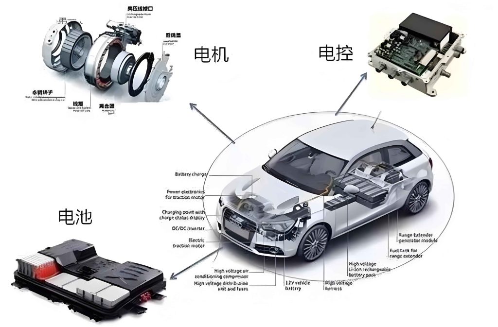
As shown in the image, modern motor control units are compact yet powerful, integrating multiple processing cores and communication interfaces. This integration enables them to handle complex tasks, from basic regulation to autonomous driving functions.
Execution Layer: Electromechanical Energy Conversion and Precision Drive Technology
The execution layer translates low-power control signals from the motor control unit into high-power mechanical actions. This involves electromechanical actuators such as electric motors, solenoids, and electrohydraulic valves. From my perspective, the efficiency and precision of these actuators determine the overall system effectiveness.
Electric motors are prevalent in execution, driven by power electronics. The torque \( \tau \) produced by a DC motor is proportional to armature current \( I_a \):
$$ \tau = K_t I_a $$
where \( K_t \) is torque constant. The motor control unit regulates current using pulse-width modulation (PWM), a technique that varies duty cycle to control average voltage. The duty cycle \( D \) is defined as:
$$ D = \frac{T_{on}}{T_{period}} $$
where \( T_{on} \) is on-time and \( T_{period} \) is switching period. PWM allows smooth speed or position control, essential for applications like electric power steering.
For precise motion, feedback from encoders or resolvers is used. The motor control unit implements closed-loop control, such as field-oriented control (FOC) for AC motors. FOC equations transform three-phase currents into d-q components:
$$ i_d = i_a \cos(\theta) + i_b \cos\left(\theta – \frac{2\pi}{3}\right) + i_c \cos\left(\theta + \frac{2\pi}{3}\right) $$
$$ i_q = -i_a \sin(\theta) – i_b \sin\left(\theta – \frac{2\pi}{3}\right) – i_c \sin\left(\theta + \frac{2\pi}{3}\right) $$
where \( \theta \) is rotor angle. This decouples torque and flux control, improving dynamic response. The motor control unit continuously adjusts PWM signals based on these computations.
Additionally, electrohydraulic actuators combine electrical control with hydraulic power. For example, in brake systems, the motor control unit commands solenoid valves to modulate pressure. The flow rate \( Q \) through a valve is given by:
$$ Q = C_d A \sqrt{\frac{2 \Delta P}{\rho}} $$
where \( C_d \) is discharge coefficient, \( A \) is area, and \( \Delta P \) is pressure drop. Such hybrid systems offer high force density, crucial for safety-critical applications.
In summary, the execution layer embodies the physical realization of mechatronic control, with the motor control unit serving as the driver. Its ability to manage energy conversion and motion precision underpins vehicle functionality.
Applications in Key Automotive Subsystems
Mechatronics permeates various vehicle subsystems, each with unique challenges and solutions. In this section, I explore three primary domains: powertrain, chassis safety, and body electronics, highlighting the pervasive role of the motor control unit.
Powertrain Systems: Synergistic Control for Fuel Economy and Performance
Powertrain mechatronics focuses on optimizing engine and transmission operation. The motor control unit, often termed Engine Control Unit (ECU) here, orchestrates fuel injection, ignition, and variable valve timing to balance power output and efficiency. From my analysis, this is achieved through torque-based management.
The motor control unit calculates target torque based on driver inputs and environmental conditions. It then coordinates actuators: electronic throttle controls air intake, while fuel injectors regulate fuel delivery. The air-fuel ratio (AFR) is maintained near stoichiometry for combustion efficiency. The ideal AFR \( \lambda \) is:
$$ \lambda = \frac{AFR_{actual}}{AFR_{stoich}} $$
where \( AFR_{stoich} \approx 14.7 \) for gasoline. The motor control unit uses oxygen sensor feedback to adjust injection pulse width, minimizing emissions.
Transmission control is equally critical. The Transmission Control Unit (TCU), a specialized motor control unit, works with the engine ECU to manage gear shifts. During shifts, the TCU requests torque reduction from the engine ECU to smooth transitions. This collaboration enhances drivability and fuel economy. Variable valve timing (VVT) systems, controlled by the motor control unit via oil pressure valves, adjust camshaft phasing dynamically. The valve timing angle \( \phi \) is optimized as:
$$ \phi = g(N_e, T_{load}) $$
where \( N_e \) is engine speed and \( T_{load} \) is load torque. This optimization expands the efficient operating range, contributing to Pareto-optimal performance.
In hybrid and electric vehicles, the motor control unit manages traction motors and battery systems. For instance, in regenerative braking, the motor control unit coordinates friction brakes and motor torque to recover kinetic energy. The power recovered \( P_{reg} \) is:
$$ P_{reg} = \eta \cdot T_m \cdot \omega_m $$
where \( \eta \) is efficiency, \( T_m \) is motor torque, and \( \omega_m \) is motor speed. Such integrations underscore the centrality of the motor control unit in modern powertrains.
Chassis Safety Systems: Dynamic Stability and Active Intervention Control
Chassis mechatronics enhances vehicle stability and safety through active interventions. Systems like Anti-lock Braking System (ABS), Traction Control System (TCS), and Electronic Stability Program (ESP) rely on motor control units to process sensor data and command actuators. From my perspective, these systems represent a shift from passive to active safety.
The motor control unit in ESP, for example, monitors yaw rate \( \dot{\psi} \) and lateral acceleration \( a_y \) using inertial sensors. It compares these with desired values from a reference model. If deviations exceed thresholds, the motor control unit applies differential braking or engine torque reduction to correct trajectory. The yaw dynamics can be modeled as:
$$ I_z \ddot{\psi} = M_z $$
where \( I_z \) is yaw inertia and \( M_z \) is yaw moment generated by braking forces. The motor control unit computes required moments and commands hydraulic modulators accordingly.
Electric power steering (EPS) is another key application. Here, a motor control unit drives an assist motor based on steering torque and vehicle speed. The assist torque \( T_{assist} \) is typically:
$$ T_{assist} = K(s) \cdot T_{driver} $$
where \( K(s) \) is a speed-dependent gain function, and \( T_{driver} \) is driver input torque. This provides variable steering feel while reducing energy consumption compared to hydraulic systems.
Active suspension systems use motor control units to adjust damper stiffness in real-time. By processing road input and body motion sensors, the motor control unit can improve ride comfort and handling. The control law might involve skyhook damping principles:
$$ F_{damper} = C_{sky} \cdot \dot{z}_{body} $$
where \( C_{sky} \) is damping coefficient and \( \dot{z}_{body} \) is body velocity. Such advancements rely heavily on the computational power of the motor control unit.
Table 2 summarizes major chassis safety systems and their reliance on the motor control unit.
| System | Primary Function | Key Sensors | Actuators | Motor Control Unit Role |
|---|---|---|---|---|
| ABS | Prevent wheel lock-up | Wheel speed sensors | Hydraulic valves | Modulates brake pressure via PWM |
| TCS | Prevent wheel spin | Wheel speed, throttle | Throttle, brakes | Reduces engine torque or applies braking |
| ESP | Maintain vehicle stability | Yaw rate, lateral accel. | Brakes, engine | Computes corrective yaw moment |
| EPS | Provide steering assist | Torque, speed sensors | Electric motor | Drives motor based on assist map |
| Active Suspension | Adapt damping | Accelerometers, displacement | Electrohydraulic actuators | Adjusts damper force in real-time |
Through these applications, the motor control unit proves indispensable for dynamic control, ensuring safety across diverse driving conditions.
Body Electronics Systems: Comfort Optimization and Human-Machine Interaction
Body electronics encompass comfort and convenience features, all enhanced by mechatronics. The Body Control Module (BCM), essentially a motor control unit, integrates functions like lighting, climate control, and seat adjustment. From my experience, these systems prioritize user experience through intelligent automation.
Automatic climate control systems use sensors for temperature, humidity, and solar radiation. The motor control unit processes these inputs to regulate blower speed and air mix doors. The control algorithm often employs PID to maintain setpoint temperature \( T_{set} \). The error \( e(t) \) is:
$$ e(t) = T_{set} – T_{cabin}(t) $$
The motor control unit adjusts actuator positions to minimize error, ensuring thermal comfort.
Lighting systems, such as adaptive front lights, use motor control units to swivel headlights based on steering angle and vehicle speed. This improves visibility during turns. The swivel angle \( \theta_{light} \) can be computed as:
$$ \theta_{light} = k \cdot \delta \cdot v $$
where \( \delta \) is steering angle, \( v \) is velocity, and \( k \) is a calibration factor. The motor control unit drives stepper motors to achieve precise alignment.
Seat adjustment modules incorporate memory functions, where the motor control unit stores positions for different users. When activated, it drives multiple motors to reposition seats, mirrors, and steering column. The coordination requires synchronized control, facilitated by the motor control unit’s multitasking capabilities.
Human-Machine Interface (HMI) elements, like touchscreens and voice recognition, also rely on motor control units for processing. For instance, in infotainment systems, the motor control unit manages display graphics and audio output, enhancing interactivity. The integration of these functions underscores the versatility of the motor control unit in body electronics.
Technological Evolution: Towards Drive-by-Wire and Integration
The future of automotive mechatronics lies in further electrification and integration. I observe two dominant trends: drive-by-wire systems and centralized electronic architectures, both heavily dependent on advanced motor control units.
Drive-by-Wire Technology: Replacing Mechanical Links
Drive-by-wire eliminates mechanical connections between driver inputs and actuators, using electronic signals instead. Steer-by-wire (SBW) and brake-by-wire (BBW) are prime examples. In these systems, the motor control unit plays a crucial role in signal processing and actuator control.
In SBW, the steering wheel angle sensor sends data to a motor control unit, which computes desired wheel angles based on vehicle dynamics. The motor control unit then commands electric motors at the rack to turn wheels. Road feel is simulated by a feedback motor, controlled by the motor control unit using algorithms that model tire forces. The feedback torque \( T_{feedback} \) might be:
$$ T_{feedback} = f_{model}(v, \mu, \theta_{wheel}) $$
where \( \mu \) is friction coefficient. This allows customizable steering feel and enables advanced features like autonomous steering.
BBW replaces hydraulic brakes with electromechanical actuators. The motor control unit interprets brake pedal sensor signals and applies braking force via electric calipers. Redundancy is critical; thus, multiple motor control units may be used for fault tolerance. The braking force \( F_b \) is proportional to pedal travel \( x \):
$$ F_b = K_{gain} \cdot x $$
where \( K_{gain} \) is adjustable by the motor control unit for different modes (e.g., sport vs. comfort). These systems reduce weight and enable integration with regenerative braking.
Overall, drive-by-wire enhances design flexibility and paves the way for autonomous vehicles, with the motor control unit as the enabler.
Electronic Architecture: From Distributed to Centralized Domains
Traditional distributed architectures, with numerous ECUs, are evolving towards domain-centralized or vehicle-computer approaches. This consolidation reduces complexity and improves scalability. In these new architectures, domain controllers—powerful motor control units—manage multiple functions.
For example, a vehicle might have domains for powertrain, chassis, body, and autonomous driving. Each domain controller integrates sensors and actuators within its domain, reducing wiring and communication overhead. The motor control unit in these controllers executes complex software, often using Service-Oriented Architecture (SOA) for flexibility.
This shift enables “software-defined vehicles,” where features can be updated remotely. The motor control unit must support over-the-air updates and secure communication. Moreover, centralized computing allows better resource allocation; for instance, a single motor control unit could handle both engine control and stability functions, optimizing performance.
Table 3 compares architectural paradigms, highlighting the role of the motor control unit.
| Architecture Type | Key Characteristics | Number of Motor Control Units | Advantages | Challenges |
|---|---|---|---|---|
| Distributed | One function per ECU | High (50-100+) | Modular, fault isolation | Complex wiring, limited synergy |
| Domain-Centralized | Domains with DCUs | Moderate (5-10) | Reduced complexity, better integration | Higher software complexity |
| Central Computer | Single high-power computer | Low (1-2) | Maximized synergy, easy updates | High reliability requirements |
As architectures evolve, the motor control unit becomes more powerful, often incorporating multicore processors and artificial intelligence accelerators for tasks like image processing in autonomous driving.
In-Vehicle Network Communication: Ensuring Real-Time Performance
Advanced mechatronic systems demand robust communication networks. Traditional CAN bus is being supplemented or replaced by high-speed protocols to support real-time data exchange between motor control units. From my analysis, this is essential for synchronized control.
Time-Sensitive Networking (TSN) over Ethernet is gaining traction for its high bandwidth and deterministic latency. In TSN, the motor control unit can schedule message transmissions to guarantee timely delivery. The latency \( L \) for a scheduled frame is bounded by:
$$ L \leq \frac{F_{size}}{B} + D_{switch} $$
where \( F_{size} \) is frame size, \( B \) is bandwidth, and \( D_{switch} \) is switch delay. This predictability is crucial for safety-critical applications like braking.
FlexRay is another protocol used in drive-by-wire systems for its fault tolerance and time-triggered nature. The motor control unit in a FlexRay network communicates in fixed time slots, ensuring no collision. The network cycle time \( T_{cycle} \) is divided into static and dynamic segments, allowing both periodic and event-driven messages.
For low-speed functions, LIN bus remains cost-effective, often managed by a master motor control unit. Table 4 summarizes key network protocols and their relevance to motor control units.
| Protocol | Trigger Mechanism | Typical Bandwidth | Real-Time Determinism | Common Use with Motor Control Unit |
|---|---|---|---|---|
| CAN/CAN FD | Event-triggered | 500 kb/s to 5 Mb/s | Moderate | Body control, powertrain |
| FlexRay | Time-triggered (TDMA) | 10 Mb/s | High | Steer-by-wire, brake-by-wire |
| LIN | Master-slave polling | 20 kb/s | Low | Windows, mirrors, lighting |
| Ethernet (TSN) | Switched/time-sensitive | 100 Mb/s to 10 Gb/s | Very High | Domain controllers, sensor fusion |
These communication advancements empower motor control units to collaborate seamlessly, enabling complex functionalities like coordinated chassis control or autonomous navigation.
Conclusion
In conclusion, mechatronics has fundamentally transformed automotive electronic control systems, with the motor control unit serving as the cornerstone of this revolution. Through my analysis, I have detailed how the integration of perception, decision, and execution layers enables precise and adaptive vehicle behavior. The applications across powertrain, chassis, and body systems demonstrate the versatility of mechatronics in enhancing efficiency, safety, and comfort. Looking ahead, trends like drive-by-wire and centralized architectures promise further advancements, albeit with challenges in real-time communication and reliability. The motor control unit will continue to evolve, incorporating more intelligence and connectivity to meet the demands of future mobility. As we progress, continued research and innovation in mechatronics will be essential to unlocking the full potential of intelligent vehicles.