
The global shift towards sustainable transportation has positioned New Energy Vehicles (NEVs) as a pivotal solution. At the heart of these vehicles lies the complex Electronic Control System (ECS), whose stability and reliability are paramount for performance, safety, and user experience. As an engineer deeply involved in vehicle service and diagnostics, I recognize that the sophistication of the ECS, integrating battery management, motor control, and vehicle coordination, presents unique challenges for fault diagnosis and repair. A systematic approach to understanding these systems and their failure modes is essential for efficient maintenance and the long-term viability of the NEV industry.
1. Overview of the NEV Electronic Control System
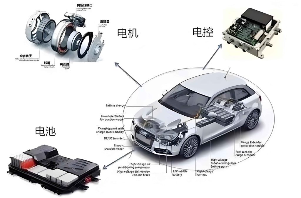
The ECS is a networked architecture of several dedicated subsystems that work in concert to manage propulsion, energy storage, and vehicle dynamics. Its primary components can be summarized as follows:
| Subsystem | Primary Function | Key Responsibilities |
|---|---|---|
| Battery Management System (BMS) | Monitor and manage the high-voltage traction battery. | Cell voltage/temperature monitoring, State of Charge (SOC) and State of Health (SOH) estimation, cell balancing, thermal management, and charge/discharge control. |
| Motor Control Unit (MCU) | Control the traction motor. | Convert DC from the battery to AC for the motor, precisely regulate motor torque, speed, and direction based on driver input and vehicle state, and implement motor protection. |
| On-Board Charger (OBC) | Manage grid charging. | Convert AC grid power to DC for battery charging, communicate with external charging equipment, and ensure safe charging protocols. |
| Vehicle Control Unit (VCU) | Act as the central coordinator. | Process sensor data (accelerator pedal, brake, speed), determine driving mode, coordinate torque requests between the motor control unit and BMS, and manage regenerative braking. |
The operational principle revolves around continuous data exchange and command execution. The BMS streams real-time battery data (e.g., voltage $V_{bat}$, current $I_{bat}$, temperature $T_{bat}$) to the VCU via the Controller Area Network (CAN). The VCU, acting as the central processor, calculates the required driving torque $T_{req}$ based on driver input and vehicle state:
$$ T_{req} = f(P_{acc}, V_{vehicle}, SOC, …) $$
This torque command is sent to the motor control unit. The motor control unit then executes precise current vector control to achieve the desired torque, governing the inverter’s switching patterns. During deceleration, the VCU commands the motor control unit to enter generator mode, converting kinetic energy back into electrical energy, which is managed by the BMS for storage. This seamless integration of data flow and control flow is the cornerstone of NEV operation.
2. Fault Typology and Root Cause Analysis
Faults in the ECS can be broadly categorized into hardware and software failures, each with distinct manifestations and origins.
2.1 Hardware Faults
These involve physical failures of electronic components and interconnections.
2.1.1 Electronic Component Failures
| Component Type | Common Failure Modes | Potential Root Causes |
|---|---|---|
| Sensors (e.g., current, temperature, position) | Signal drift, offset, complete signal loss, or erroneous readings. | Aging of sensing elements, physical damage from vibration/impact, contamination, and electromagnetic interference (EMI) corrupting signal integrity. |
| Power Electronics (e.g., IGBTs, MOSFETs in the motor control unit inverter) | Short-circuit, open-circuit, gate degradation, leading to motor jerk, loss of power, or excessive heat. | Thermal overstress $(T_j > T_{jmax})$, electrical overstress (overcurrent $I > I_{max}$, overvoltage), solder fatigue, and intrinsic manufacturing defects. |
A failed current sensor in the motor control unit can provide incorrect feedback $I_{fb}$, causing the controller to miscalculate the applied voltage. If the true motor current $I_{actual}$ deviates significantly from the measured $I_{fb}$, the control error $e_I$ can lead to instability:
$$ e_I = I_{ref} – I_{fb} \quad \text{where } I_{fb} \neq I_{actual} $$
This results in torque ripple, reduced efficiency, or even a protective shutdown.
2.1.2 Wiring and Connection Faults
| Fault Type | Symptoms | Root Causes |
|---|---|---|
| Open Circuit | Subsystem deactivation, loss of sensor data, “floating” signals. | Vibration-induced wire fatigue, corrosion at connectors, poor crimping, or physical wire breakage due to abrasion. |
| Short Circuit (Power-to-Power, Power-to-Ground, Signal-to-Signal) | Fuse blowing, component burnout, anomalous system behavior, or parasitic power drains. | Insulation breakdown due to heat aging, chafing against sharp edges, rodent damage, or moisture ingress leading to electrochemical migration. |
2.2 Software and Network Faults
These are failures in the logical layer controlling the hardware.
2.2.1 Control Logic and Application Software Faults
Faults originate in the software running on the VCU, BMS, or motor control unit. A bug in the torque control algorithm of the motor control unit firmware could miscalculate the quadrature current reference $I_{q\_ref}$, directly impacting output torque $T_e$:
$$ T_e = \frac{3}{2} p (\psi_{pm} I_q + (L_d – L_q) I_d I_q) $$
If $I_{q\_ref}$ is erroneously computed, $T_e$ will be incorrect.
| Manifestation | Examples | Root Causes |
|---|---|---|
| Functional Anomalies | Uncommanded acceleration/creep, regenerative braking failure, incorrect SOC display, HVAC system malfunction. | Algorithmic logic errors, race conditions, stack overflow, improper handling of boundary conditions in the software code. |
| Update & Compatibility Issues | System instability or bricking after a firmware flash. | Incompatible firmware version, corrupted download, interrupted programming sequence, or mismatch between new software and legacy hardware. |
2.2.2 In-Vehicle Network Communication Faults
The CAN bus is the nervous system of the ECS. Faults here disrupt the critical data flow between the VCU, BMS, and motor control unit.
| Fault Type | Impact | Root Causes |
|---|---|---|
| Bus Off / Node Failure | Complete loss of communication from a specific ECU (e.g., the motor control unit goes silent). | Transceiver IC failure, local power supply issue to the ECU, or the ECU entering a “bus-off” error state due to excessive transmission errors. |
| Signal Integrity Issues | Intermittent communication, corrupted messages, increased error frames. | Poor termination (incorrect termination resistance $R_T$, where nominal $R_T \approx 120\Omega$ for standard CAN), EMI, damaged CAN_H or CAN_L wiring, or ground potential differences between nodes. |
The characteristic impedance $Z_0$ of the CAN bus twisted pair is crucial. Mismatch can cause reflections and data corruption:
$$ Z_0 = \sqrt{\frac{L}{C}} $$
where $L$ is inductance per unit length and $C$ is capacitance per unit length. Damage to the wiring alters $C$ and $L$, degrading $Z_0$.
3. Systematic Maintenance and Repair Strategies
An effective repair strategy moves from accurate diagnosis to precise intervention, differing for hardware and software faults.
3.1 Hardware Repair Protocols
3.1.1 Electronic Component Replacement
This requires precision and adherence to Electrostatic Discharge (ESD) safety. For surface-mount devices (SMDs) on a motor control unit board, controlled soldering is key. The reflow profile must be respected. The peak temperature $T_{peak}$ and time above liquidus $t_{L}$ are critical:
$$ T_{peak} = T_{liquidus} + \Delta T_{overheat} \quad \text{(typically 220-260°C)} $$
$$ t_{L} \approx 30 – 90 \text{ seconds} $$
Post-replacement, subsystems often require calibration. For instance, replacing a resolver in the motor linked to the motor control unit requires an offset calibration procedure to align the electrical angle with the mechanical rotor position.
3.1.2 Wiring Harness Repair
Repairs must restore mechanical strength, electrical conductivity, and environmental sealing. For a high-voltage cable, the repair process is stringent. After identifying a break using continuity check ($R \rightarrow \infty$), the repair involves:
- Stripping insulation to a precise length $L_s$.
- Applying a crimp or solder splice with a cross-sectional area $A_{repair} \geq A_{original}$ to maintain current rating.
- Insulating with dual-walled heat-shrink tubing, ensuring a minimum shrink ratio and adhesive sealant activation above a specific temperature $T_{shrink}$.
Routing and securing the repaired harness away from heat sources and sharp edges is mandatory to prevent recurrence.
3.2 Software and Network Remediation
3.2.1 Control Program Reflashing and Patch Management
This is performed via a diagnostic interface (e.g., OBD-II with CAN). The process for updating the motor control unit firmware involves:
- Downloading the correct firmware binary file and checksum from the manufacturer.
- Establishing a diagnostic session with the motor control unit.
- Erasing the memory sector, programming the new data, and verifying using a checksum algorithm (e.g., CRC-32):
$$ CRC32 = \sum_{i=0}^{n-1} (data[i] \cdot x^{n-1-i}) \mod g(x) $$
where $g(x)$ is the generator polynomial. A mismatch indicates a corrupted flash.
- Resetting the motor control unit and performing a basic functional test.
3.2.2 Communication Network Troubleshooting
A methodical approach is required for CAN faults.
- Visual Inspection: Check termination resistors, connector integrity, and wire condition.
- Static Measurement: With power off, measure DC resistance between CAN_H and CAN_L at the central point. It should approximate $R_T/2$ (≈60Ω) for a properly terminated bus with two terminators.
- Dynamic Analysis with Oscilloscope: Probe CAN_H and CAN_L signals with respect to ground. A healthy differential signal (CAN_H – CAN_L) should show a clean, square waveform. Noise, asymmetry, or amplitude decay indicate problems. The differential voltage $V_{diff}$ should toggle between dominant (~2-3V) and recessive (~0V) states cleanly.
- Node Isolation: Suspect nodes can be disconnected one by one to see if bus communication resumes, identifying the faulty ECU.
4. Conclusion and Future Perspectives
A deep understanding of the NEV ECS’s architecture, its failure modes, and corresponding repair strategies is fundamental for maintaining vehicle safety and reliability. The motor control unit, as a critical actuator, is frequently at the center of both performance issues and repair procedures. The future of NEV maintenance lies in advancing predictive diagnostics through data-driven models. Integrating time-series data from the BMS, motor control unit, and VCU into machine learning algorithms can enable early fault detection before a catastrophic failure occurs. Furthermore, the development of more robust power modules, self-diagnosing software architectures, and standardized, secure over-the-air update protocols will significantly enhance system resilience and reduce downtime. Continuous innovation in both diagnostic methodologies and repair technologies is essential to support the sustainable growth of the new energy vehicle ecosystem.