
As a practitioner deeply involved in the field of new energy vehicle (NEV) maintenance, I have witnessed the rapid evolution of electric control systems and the growing complexities associated with their repair. The electric control system is the core of NEV operation, directly influencing performance, safety, and longevity. In this article, I will share my insights and strategies for diagnosing and repairing common faults in NEV electric control systems, with a focus on practical applications. Drawing from hands-on experience, I aim to provide a comprehensive guide that integrates theoretical principles with actionable维修 techniques. Throughout this discussion, I will emphasize the critical role of the motor control unit (MCU) and other key components, utilizing tables and formulas to summarize key points for clarity and depth.
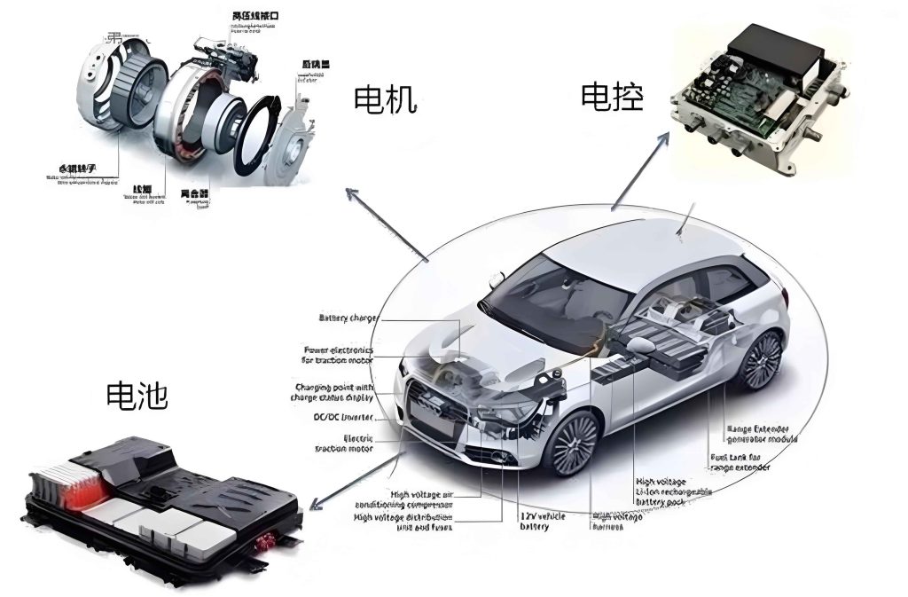
The electric control system in NEVs is a sophisticated network comprising several interconnected subsystems. Primarily, it includes the battery management system (BMS), the motor control unit (MCU), and the vehicle control unit (VCU). These systems work in harmony to manage energy flow, ensure operational stability, and protect against failures. Fundamentally, energy conversion occurs between the battery and the motor: the battery supplies direct current (DC) power, which is converted by an inverter into alternating current (AC) to drive the motor. This process can be expressed using power efficiency formulas, where the output power depends on conversion losses. For instance, the overall efficiency of the power conversion can be represented as:
$$P_{\text{out}} = \eta \cdot P_{\text{in}}$$
Here, $P_{\text{in}}$ is the input power from the battery, $P_{\text{out}}$ is the output power to the motor, and $\eta$ is the efficiency factor (typically between 0.9 and 0.95 for modern systems). The motor control unit plays a pivotal role in this conversion by regulating motor speed and torque through pulse-width modulation (PWM) techniques. The relationship between motor torque $T$, current $I$, and magnetic flux $\Phi$ can be approximated by:
$$T = k \cdot \Phi \cdot I$$
where $k$ is a motor constant. Understanding these principles is essential for effective故障 diagnosis, as deviations from expected values often indicate underlying issues.
To better illustrate the system architecture, I have summarized the key components and their functions in the following table:
| Component | Primary Function | Common Parameters Monitored |
|---|---|---|
| Battery Management System (BMS) | Monitors battery health, balances cells, manages temperature | Cell voltage, current, state of charge (SOC), temperature |
| Motor Control Unit (MCU) | Controls motor operation, converts DC to AC, manages torque/speed | Motor current, voltage, frequency, temperature |
| Vehicle Control Unit (VCU) | Coordinates overall vehicle systems, implements driving strategies | Throttle input, brake signals, energy distribution |
| Inverter | Converts DC from battery to AC for motor | Input/output voltage, switching frequency, efficiency |
In my experience, failures in these systems often manifest as performance degradation or complete shutdowns. Two of the most prevalent故障 areas are the battery management system and the charging system. For the BMS, faults can lead to cell imbalance, where individual battery cells deviate in voltage or capacity, causing reduced range and potential safety hazards. The imbalance can be quantified using the standard deviation of cell voltages:
$$\sigma_V = \sqrt{\frac{1}{N} \sum_{i=1}^{N} (V_i – \bar{V})^2}$$
where $V_i$ is the voltage of the $i$-th cell, $\bar{V}$ is the average voltage, and $N$ is the number of cells. A high $\sigma_V$ indicates significant imbalance, necessitating cell replacement or rebalancing. Temperature anomalies are another common issue, often due to failed sensors or coolant pump failures in the thermal management system. The motor control unit is also prone to faults, such as overheating or PWM signal distortions, which can stem from defective insulated-gate bipolar transistors (IGBTs) or software glitches. I recall instances where a malfunctioning motor control unit caused erratic acceleration, highlighting the need for thorough diagnostics.
When addressing charging system faults, the challenges multiply due to the interaction between onboard chargers, charging ports, and external infrastructure. Common symptoms include slow charging or complete failure to charge. Diagnostic approaches must consider multiple factors, such as connector integrity, cable resistance, and communication protocols. For example, the charging current $I_{\text{charge}}$ can be modeled by Ohm’s law accounting for losses:
$$I_{\text{charge}} = \frac{V_{\text{supply}} – V_{\text{battery}}}{R_{\text{total}}}$$
where $V_{\text{supply}}$ is the external charger voltage, $V_{\text{battery}}$ is the battery pack voltage, and $R_{\text{total}}$ is the total resistance in the charging path. An elevated $R_{\text{total}}$ due to corroded contacts or damaged cables can severely limit charging speed. In practice, I use specialized diagnostic tools to scan for故障 codes and monitor real-time parameters during charging cycles. The integration of the motor control unit with the charging system is sometimes overlooked; for instance, regenerative braking signals processed by the motor control unit can affect charging logic, so a holistic view is crucial.
Based on my维修实践, I have developed a systematic strategy for electric control system maintenance. The first step involves comprehensive component testing, starting with the battery system. I begin by inspecting individual battery cells using a multimeter to measure voltage and internal resistance. For a pack with $N$ cells, the total pack voltage $V_{\text{pack}}$ should equal the sum of cell voltages if connections are ideal:
$$V_{\text{pack}} = \sum_{i=1}^{N} V_i$$
Deviations often point to faulty cells or balancing circuits. Advanced diagnostic devices can read BMS data logs to identify anomalies in state of health (SOH) or temperature gradients. Similarly, for the thermal management system, I test sensors (e.g., thermocouples) for accuracy and check pump operation by measuring flow rates. The following table outlines a typical diagnostic workflow for battery system faults:
| Step | Action | Tools Used | Expected Outcome |
|---|---|---|---|
| 1 | Visual inspection of battery pack and connections | Flashlight, inspection camera | No physical damage or corrosion |
| 2 | Measure cell voltages and internal resistance | Multimeter, battery analyzer | All cells within ±0.05 V of average |
| 3 | Scan BMS for故障 codes | OBD-II scanner, proprietary software | No critical故障 codes |
| 4 | Test thermal management components | Thermometer, flow meter | Sensors accurate, pump functional |
| 5 | Load testing for capacity verification | Load bank, dyno | Capacity within 80% of rated value |
For charging system repairs, the approach is methodical. I first examine the charging port and cable for wear or debris, as poor contacts increase resistance and generate heat. Using a diagnostic tool, I initiate a charging session while monitoring parameters like input voltage, current, and temperature. The motor control unit often interfaces with the charging system to manage power flow, so I ensure its software is updated and its signals are consistent. If通信 faults are detected, I check the controller area network (CAN) bus for errors, as the motor control unit communicates via CAN with other ECUs. In one case, a corrupted firmware in the motor control unit led to intermittent charging failures, which was resolved by reprogramming the unit. To summarize charging system diagnostics, I use a formula-based check: the energy transferred during charging $E$ should align with the time-integral of power, considering efficiency $\eta_c$:
$$E = \eta_c \int_{0}^{t} V(t) I(t) dt$$
Discrepancies here indicate losses or faults in the conversion chain.
Beyond these common faults, I have encountered scenarios where the motor control unit itself fails due to environmental stressors like vibration or moisture ingress. The motor control unit is essentially a high-power electronic controller that regulates three-phase AC motors, and its reliability is paramount. I often perform insulation resistance tests on the motor control unit’s power terminals to prevent short circuits. The resistance $R_{\text{ins}}$ should exceed a threshold (e.g., 1 MΩ) as per standards:
$$R_{\text{ins}} > R_{\text{min}}$$
where $R_{\text{min}}$ is specified by the manufacturer. Additionally, the motor control unit’s cooling system must be maintained; blocked heat sinks can cause thermal shutdowns. In my维修策略, I emphasize preventive maintenance for the motor control unit, including regular software updates and connector inspections. The interplay between the motor control unit and the BMS is also critical; for instance, during regenerative braking, the motor control unit sends current back to the battery, and the BMS must manage this influx to avoid overcharging. Thus, a协同 approach is necessary.
To enhance维修 efficiency, I advocate for the use of advanced电子诊断 technologies, such as oscilloscopes to analyze PWM signals from the motor control unit or infrared cameras to detect hotspots. Data analytics can also predict failures by tracking trends in parameters like motor current ripple or battery impedance rise. For example, the impedance $Z$ of a battery cell can be modeled as a function of frequency $f$ and temperature $T$:
$$Z(f, T) = R_s + \frac{R_{ct}}{1 + j 2\pi f R_{ct} C_{dl}}$$
where $R_s$ is series resistance, $R_{ct}$ is charge transfer resistance, and $C_{dl}$ is double-layer capacitance. Gradual increases in $R_s$ may indicate aging, prompting preemptive replacement. Integrating such models into diagnostic protocols allows for proactive maintenance, reducing downtime. Furthermore, simulation tools can replicate故障 conditions, aiding in technician training. I often simulate motor control unit faults to practice troubleshooting without risking actual hardware.
Looking ahead, the evolution of NEV electric control systems will introduce new challenges, such as higher voltage architectures (e.g., 800V systems) and integrated power units that combine the motor control unit with the inverter. These advancements demand updated维修 strategies and tools. For instance, safety protocols for high-voltage systems require insulated tools and rigorous lockout-tagout procedures. The motor control unit in such systems may incorporate silicon carbide (SiC) transistors for higher efficiency, but these are sensitive to voltage spikes, necessitating careful handling during repairs. I believe continuous learning and adaptation are key for维修 technicians to stay abreast of these changes.
In conclusion, effective maintenance of NEV electric control systems hinges on a deep understanding of their principles and a systematic approach to故障 diagnosis. By combining theoretical knowledge with practical tools—and always keeping the motor control unit at the forefront of analysis—we can ensure reliable and safe vehicle operation. The strategies discussed here, from battery cell testing to charging system checks, form a robust framework for tackling common issues. As NEVs become more prevalent, refining these维修 techniques will be essential for sustaining the industry’s growth and consumer trust.