
As a researcher focused on automotive technologies, I have observed the rapid adoption of new energy vehicles (NEVs) globally, driven by their advantages in low-carbon emissions and energy efficiency. However, the electronic control systems (ECS) in NEVs face significant challenges, with electromagnetic interference (EMI) being a prominent issue. EMI refers to the adverse effects of electromagnetic fields on the performance of electronic devices and systems. In NEV ECS, which comprise numerous electronic components and sensors, EMI can arise from internal radiation or external environmental sources, potentially disrupting system functionality, causing vehicle failures, and even compromising safety. Therefore, in-depth research into EMI fault diagnosis and repair is crucial for enhancing NEV performance and safety.
In this article, I will explore the EMI aspects of NEV ECS from a first-person perspective, drawing on technical insights and practical experiences. I aim to provide a comprehensive analysis, incorporating tables and formulas to summarize key concepts, and emphasize the role of the motor control unit (MCU) throughout. The motor control unit is a critical component in managing vehicle propulsion, and its susceptibility to EMI warrants repeated attention. By structuring the discussion around system overview, interference mechanisms, fault causes, repair methods, and a case study, I hope to offer valuable guidance for improving electromagnetic compatibility (EMC) in NEVs.
Overview of NEV Electronic Control System
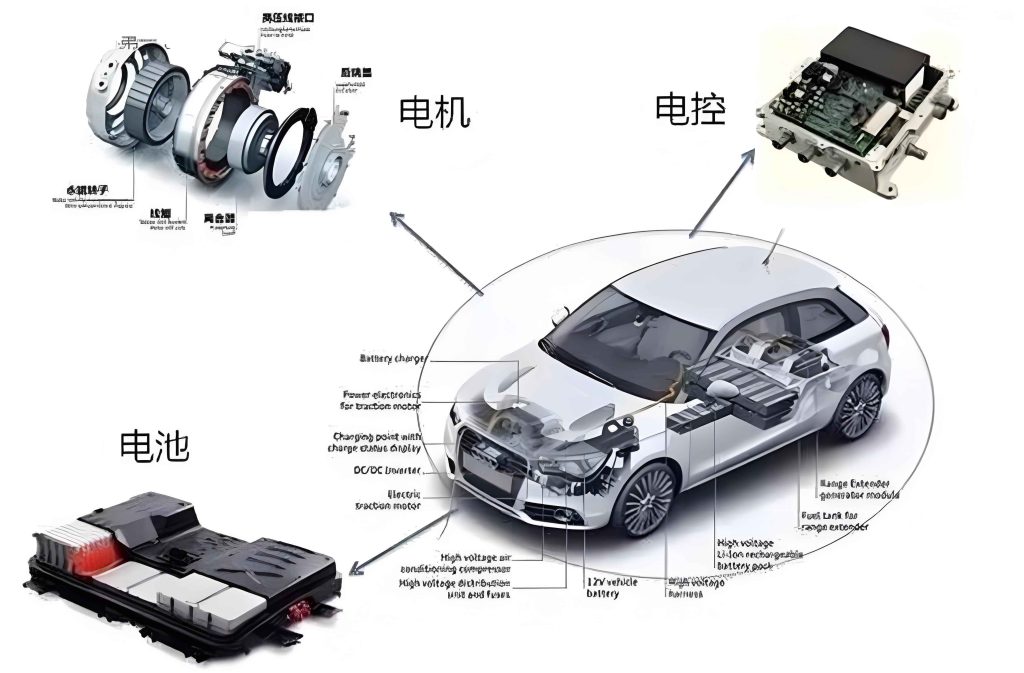
The NEV electronic control system is an integrated network that coordinates vehicle operations, primarily consisting of the battery management system (BMS), motor control unit (MCU), and vehicle control unit (VCU). These components interact via complex wiring and sensor arrays to enable precise control over the powertrain. The motor control unit, in particular, regulates motor speed and torque based on driver inputs and vehicle conditions, facilitating acceleration, deceleration, and braking. Below is a table summarizing the core components and their functions:
| Component | Function | Key Parameters |
|---|---|---|
| Battery Management System (BMS) | Monitors voltage, current, and temperature of battery packs to ensure safety and efficiency. | Voltage range: 200-400 V, temperature tolerance: -20°C to 60°C. |
| Motor Control Unit (MCU) | Controls electric motor operations by adjusting frequency and current; pivotal for torque management. | Power output: up to 150 kW, efficiency: >95%. |
| Vehicle Control Unit (VCU) | Acts as the central processor, coordinating BMS, MCU, and other subsystems for seamless operation. | Processing speed: 100 MHz, communication protocols: CAN, LIN. |
The NEV ECS is characterized by high integration, intelligence, and networking. Integrated design reduces size and weight but increases EMI risks due to closer component proximity. Intelligence and networking enhance performance but demand higher reliability and EMC. The motor control unit exemplifies this, as its compact design may amplify susceptibility to interference. To quantify system behavior, we can use formulas like the power efficiency of the motor control unit: $$ \eta_{MCU} = \frac{P_{out}}{P_{in}} \times 100\% $$ where \( P_{out} \) is the output power and \( P_{in} \) is the input power. Optimal performance requires \( \eta_{MCU} > 95\% \), but EMI can degrade this by introducing noise in control signals.
Electromagnetic Interference in NEV ECS
EMI in NEV ECS originates from both internal and external sources, affecting system stability through conduction and radiation coupling. Understanding these mechanisms is essential for effective fault management.
EMI Sources
Internal interference stems from electronic components within the ECS. For instance, the ignition system, generators, motors, and relays emit electromagnetic radiation during operation. The motor control unit, with its high-frequency switching circuits, can generate significant EMI. External interference comes from outside sources like power lines, broadcast equipment, and natural events such as lightning. The table below categorizes EMI sources:
| Source Type | Examples | Impact on ECS |
|---|---|---|
| Internal | Ignition coils, motor control unit, relays | Direct radiation via wires or space coupling; can disrupt sensor signals. |
| External | High-voltage lines, radio transmitters, lightning | Induced currents through antennas or gaps; may cause system malfunctions. |
EMI Mechanisms
EMI propagates via conduction coupling and radiation coupling. Conduction coupling involves interference signals traveling through conductors like wires. For example, transient voltages from the ignition system can spread through circuits, modeled by: $$ V_{noise} = L \frac{di}{dt} + iR $$ where \( L \) is inductance, \( i \) is current, and \( R \) is resistance. This noise can affect the motor control unit by altering input signals. Radiation coupling entails EMI propagating as electromagnetic waves through space, described by the field strength equation: $$ E = \frac{k I f}{r} $$ where \( E \) is electric field strength, \( I \) is current, \( f \) is frequency, \( r \) is distance, and \( k \) is a constant. Waves can penetrate vehicle seams, interfering with the motor control unit and other components. The motor control unit’s sensitivity to such interference necessitates robust shielding, as even minor disruptions can lead to torque fluctuations.
Causes of EMI Faults in NEV ECS
EMI faults arise from various sources within NEVs, each contributing to system degradation. Below, I detail key causes, emphasizing how the motor control unit is often implicated.
| Fault Cause | Description | Effect on Motor Control Unit |
|---|---|---|
| Ignition System EMI | High-frequency radiation from ignition coils and sparks during circuit interruption. | Induces transient voltages in MCU wiring, causing erroneous torque commands. |
| Alternator Charging System EMI | Sparks from brushes and voltage regulators generate broadband interference. | Noise in power supply lines disrupts MCU’s current regulation, reducing efficiency. |
| Motor EMI | Starters, fans, and wiper motors produce sparks and electromagnetic waves during operation. | Startup surges from motors couple into MCU circuits, leading to signal distortion. |
| Relay Contact EMI | High-speed switching of relays creates transient interference with wide frequency spectra. | Radiated waves affect MCU’s logic circuits, potentially triggering false shutdowns. |
| Auxiliary Device EMI | Aftermarket additions like audio systems emit interference from inductive components. | Unshielded cables near MCU introduce noise, impairing control accuracy. |
The motor control unit is particularly vulnerable due to its role in processing low-voltage signals amidst high-power environments. For instance, EMI from the alternator can be quantified by the noise power formula: $$ P_{noise} = \frac{V_{rms}^2}{R} $$ where \( V_{rms} \) is the root-mean-square noise voltage and \( R \) is impedance. If \( P_{noise} \) exceeds thresholds, the motor control unit may misinterpret data, causing performance drops. Repeated exposure to such interference accelerates wear, underscoring the need for proactive maintenance.
EMI Fault Diagnosis and Repair Methods
Effective EMI fault检修 requires a systematic approach, blending diagnostic tools and analytical techniques. As a practitioner, I advocate for a multi-step process that prioritizes the motor control unit’s integrity.
Diagnostic思路 Clarification
First, I establish a clear检修思路 by analyzing fault symptoms, scoping possible areas, and preparing tools like code readers, oscilloscopes, and multimeters. The motor control unit should be a focal point, given its centrality to vehicle dynamics. A table summarizes this phase:
| Step | Action | Tool | Goal |
|---|---|---|---|
| 1 | Symptom analysis | Visual inspection, driver reports | Identify patterns (e.g., intermittent shutdowns). |
| 2 | Fault scoping | Circuit diagrams, EMC knowledge | Narrow down to subsystems like MCU or BMS. |
| 3 | Tool preparation | Oscilloscope, multimeter, code scanner | Enable precise measurements of EMI effects. |
| 4 | Procedure planning | Structured checklist | Ensure methodical troubleshooting from external to internal checks. |
Fault Exclusion Analysis
Next, I conduct fault exclusion using diagnostic tools. Code readers retrieve fault codes from the ECS, often pointing to the motor control unit. Parameter testing involves measuring ranges and sensitivities; for the motor control unit, key parameters include input voltage \( V_{in} \) and output frequency \( f_{out} \), compared against norms: $$ \Delta V = |V_{measured} – V_{nominal}| $$ If \( \Delta V > 0.1V \), EMI may be present. Waveform analysis with an oscilloscope reveals anomalies; for instance, a noisy signal in the motor control unit’s PWM output can be modeled as: $$ S(t) = A \sin(2\pi ft) + N(t) $$ where \( N(t) \) represents EMI noise. By comparing to clean waveforms, I pinpoint interference sources.
Optimized Repair方案
Based on analysis, I optimize the repair方案 by locating interference sources, implementing shielding, adjusting parameters, and verifying fixes. Shielding effectiveness for the motor control unit can be expressed as: $$ SE = 20 \log_{10} \left( \frac{E_{unshielded}}{E_{shielded}} \right) \text{ dB} $$ where higher SE values indicate better protection. Practical steps include adding ferrite cores or enclosures around the motor control unit. Parameter adjustments might involve recalibrating the motor control unit’s response curves using software tools. Finally, validation through road tests ensures EMI is mitigated, with the motor control unit operating stably. The table below outlines this phase:
| Repair Aspect | Technique | Application to Motor Control Unit |
|---|---|---|
| Source localization | Near-field probes, spectrum analyzers | Identify EMI hotspots near MCU wiring harnesses. |
| Shielding implementation | Metallic enclosures, grounded shields | Encase MCU to attenuate radiated interference by 20-30 dB. |
| Parameter adjustment | Software recalibration, filter tuning | Modify MCU’s gain settings to reject noise frequencies. |
| Fault verification | Dynamic testing, EMC compliance checks | Confirm MCU outputs remain within specs under load. |
Case Study: EMI-Induced Startup Failure
To illustrate, I recall a case where an NEV failed to start, with dashboard fault codes indicating ignition issues. Using a code reader, I retrieved a code linked to the ignition system, suggesting EMI involvement. Parameter testing revealed abnormal voltage fluctuations in the ignition coil’s primary circuit, adjacent to the motor control unit. Oscilloscope waveforms showed transient spikes, modeled as: $$ V_{spike} = V_0 e^{-t/\tau} \cos(2\pi f_c t) $$ where \( \tau \) is the decay constant and \( f_c \) is the carrier frequency. These spikes correlated with noise in the motor control unit’s sensor inputs. Further analysis pinpointed the ignition coil as the EMI source, radiating interference that affected the motor control unit’s startup sequence. By shielding the coil and replacing a damaged motor control unit connector, I resolved the fault. Post-repair verification involved monitoring the motor control unit’s signals during ignition; the waveforms stabilized, and the vehicle started reliably. This case underscores how EMI can cascade from components like ignition systems to critical units like the motor control unit, necessitating holistic检修.
Conclusion and Future Perspectives
In summary, EMI in NEV ECS poses significant challenges, but through systematic diagnosis and repair, we can enhance system resilience. The motor control unit, as a linchpin of vehicle control, demands particular attention in EMI mitigation. I have detailed sources, mechanisms, and检修 methods, emphasizing the use of formulas and tables for clarity. For instance, conduction coupling can be minimized by optimizing layout using the crosstalk formula: $$ X_{talk} = \frac{C_m}{C_g} V_{drive} $$ where \( C_m \) is mutual capacitance and \( C_g \) is ground capacitance. Future research should focus on advanced EMC designs, such as integrating AI-based noise cancellation in the motor control unit, or developing standards for EMI tolerance. As NEVs evolve, continued innovation in shielding materials and diagnostic tools will be vital. By prioritizing the motor control unit’s EMI robustness, we can ensure safer, more efficient vehicles, contributing to sustainable transportation globally.