
In modern automotive education, the integration of work and study has emerged as a pivotal approach to cultivating high-skilled technicians capable of addressing real-world challenges. As an educator specializing in automotive technology, I have implemented this methodology in teaching electronic diesel engine maintenance, focusing on hands-on tasks that mirror industry scenarios. This article delves into my first-person experience with work-study integrated teaching, emphasizing the role of the motor control unit in fault diagnosis and repair. Through detailed processes, tables, and formulas, I aim to provide a comprehensive guide for enhancing student competency in this critical area.
The work-study integrated teaching model is grounded in national vocational skill standards and aims to develop comprehensive professional abilities by merging work processes with learning processes. In automotive repair education, this translates to a structured workflow that I adhere to in my courses. The process typically involves six key stages: clarifying the task, confirming fault phenomena, analyzing fault causes, formulating and deciding on repair plans, implementing repair operations, and conducting summary evaluations. This cyclic approach ensures that students not only grasp theoretical knowledge but also apply it in practical settings, thereby bridging the gap between classroom learning and workplace demands. The motor control unit serves as the central component in electronic diesel engines, orchestrating functions such as fuel injection timing and emission control, making its understanding crucial for effective maintenance.
Electronic diesel engines differ from traditional ones primarily in their fuel supply and electronic control systems. The core components include sensors, the motor control unit, actuators, and basic elements like fuel pumps and injectors. For instructional purposes, I use the Great Wall GW2.8tc diesel engine as a case study, as its systems are representative of contemporary designs. The motor control unit processes inputs from various sensors—such as coolant temperature, crankshaft position, and camshaft position sensors—to regulate fuel delivery via actuators like the fuel metering valve and injectors. This interplay is essential for engine performance, and any malfunction can lead to issues like failure to start. To visualize this system, I often incorporate multimedia resources; for instance, consider the following illustration of a typical motor control unit setup:
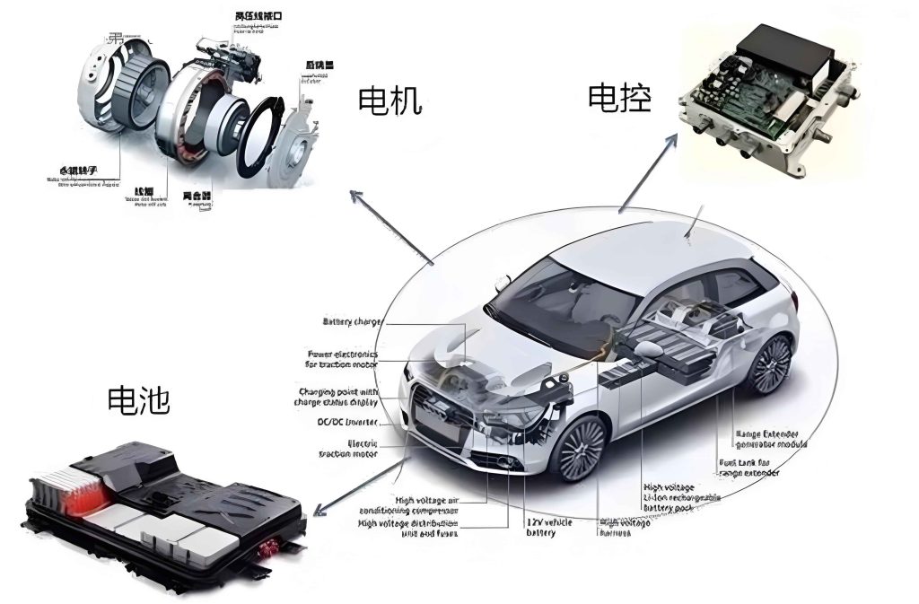
This image highlights the complexity and integration of components, reinforcing the need for systematic teaching.
In my teaching practice, I structure the electronic diesel engine maintenance course around a real-world task: diagnosing and repairing a no-start fault. This task encompasses multiple systems and requires students to engage in all six stages of the work-study process. Below, I outline each stage with supporting tables and formulas to summarize key concepts.
Stage 1: Clarifying the Task
I introduce the learning task through a scenario: a 2007 Havel H3 SUV with a GW2.8tc diesel engine fails to start after accumulating 138,000 kilometers. Students read the task description and extract keywords to understand requirements. This mimics real repair orders, fostering professionalism. The motor control unit is implicitly central, as its signals dictate engine behavior. I emphasize that tasks must be approached methodically, starting with safety checks and documentation.
Stage 2: Confirming Fault Phenomena
Students observe my demonstration of fault confirmation, then perform it in groups. They install protective covers, check battery voltage, and attempt ignition while noting observations like starter motor sounds and exhaust smoke. A table helps organize findings:
| Step | Observation | Normal Value | Recorded Value |
|---|---|---|---|
| Battery Voltage | Measured with multimeter | 12.6 V | 12.5 V |
| Starter Operation | Sound during ignition | Smooth cranking | Audible cranking |
| Exhaust Smoke | Visual inspection | Minimal smoke | No smoke |
This systematic confirmation narrows down potential causes, highlighting the importance of the motor control unit in coordinating startup sequences.
Stage 3: Analyzing Fault Causes
Based on the electronic diesel engine startup control principle, I guide students through brainstorming sessions. The motor control unit relies on sensor inputs to compute parameters like fuel injection timing. Using a cause-and-effect diagram, students list possible reasons for no-start faults. A formula illustrates the relationship: the fuel injection quantity during startup is calculated by the motor control unit as $$Q_{inj} = f(T_{coolant}, N_{engine}, P_{rail})$$ where \(Q_{inj}\) is injection quantity, \(T_{coolant}\) is coolant temperature, \(N_{engine}\) is engine speed, and \(P_{rail}\) is rail pressure. Faults can arise from deviations in these variables. Table 2 summarizes common causes:
| System | Potential Fault | Impact on Motor Control Unit |
|---|---|---|
| Fuel Supply | Low pressure in common rail | Insufficient signal for injection |
| Sensors | Faulty crankshaft position sensor | Loss of timing reference |
| Actuators | Stuck fuel metering valve | Improper fuel regulation |
| Electrical | Wiring issues to motor control unit | Signal interruption |
This analysis reinforces how the motor control unit integrates data for decision-making.
Stage 4: Formulating and Deciding on Repair Plans
Students consult repair manuals and videos to draft repair plans, emphasizing safety and efficiency. The plans follow a logical flow from external checks to internal components, always considering the motor control unit’s role. A decision matrix aids in selecting the best approach:
| Option | Complexity | Time Required | Tools Needed | Priority |
|---|---|---|---|---|
| Check fuel lines | Low | 10 minutes | Wrench, pressure gauge | High |
| Test sensor signals | Medium | 20 minutes | Multimeter, oscilloscope | Medium |
| Inspect motor control unit connections | High | 30 minutes | Diagnostic tool, wiring diagram | Low |
Through group presentations and critiques, students refine their plans, ensuring alignment with technical standards. The motor control unit is often the focal point, as its diagnostics require specialized knowledge.
Stage 5: Implementing Repair Operations
In this hands-on stage, students work in teams at repair stations. I supervise while they execute their plans, using tools like multimeters and diagnostic scanners. Key steps involve testing components related to the motor control unit. For example, to verify the coolant temperature sensor, students measure resistance and voltage. The sensor’s resistance-temperature characteristic can be modeled as $$R(T) = R_0 \exp\left(B\left(\frac{1}{T} – \frac{1}{T_0}\right)\right)$$ where \(R_0\) is resistance at reference temperature \(T_0\), and \(B\) is a material constant. Students record values in a table:
| Component | Test | Expected Value | Measured Value | Judgment |
|---|---|---|---|---|
| Coolant Sensor | Resistance at 20°C | 2.5 kΩ | 2.48 kΩ | Normal |
| Crankshaft Sensor | Air gap | 0.8-1.0 mm | 0.9 mm | Normal |
| Fuel Metering Valve | Resistance | 3 Ω | 3.1 Ω | Normal |
| Motor Control Unit Output | Voltage pulse | 5 V peak | 5 V observed | Functional |
During one session, students discovered miswired injector connectors—a fault that disrupted signals from the motor control unit. After correction, the engine started successfully. This practical experience underscores the motor control unit’s sensitivity to electrical integrity.
Stage 6: Conducting Summary Evaluations
Post-task, students complete self-assessments and peer reviews, focusing on safety, teamwork, and technical accuracy. I provide holistic feedback, highlighting areas like adherence to procedures and understanding of the motor control unit’s functions. A scoring rubric quantifies performance:
| Criteria | Weight | Student Score (Avg.) | Comments |
|---|---|---|---|
| Fault Analysis | 30% | 85% | Adequate use of motor control unit data |
| Repair Implementation | 40% | 90% | Proficient tool handling |
| Safety Compliance | 20% | 95% | No incidents recorded |
| Team Collaboration | 10% | 80% | Effective communication |
This evaluation fosters reflection and continuous improvement, ensuring students internalize lessons about the motor control unit and its maintenance.
The work-study integrated approach has yielded measurable outcomes in my teaching context. After implementing this model, student pass rates for skill certifications increased by 20% in a sample of 50 learners, and partner enterprises reported a 15% rise in job suitability evaluations for graduates. These gains stem from enhanced practical abilities, particularly in diagnosing faults involving the motor control unit. For instance, students now routinely use formulas like $$V_{signal} = V_{ref} \times \frac{R_{sensor}}{R_{sensor} + R_{fixed}}$$ to analyze sensor circuits, where \(V_{signal}\) is input to the motor control unit. This mathematical rigor complements hands-on skills, producing well-rounded technicians.
In conclusion, the work-study integrated teaching method for electronic diesel engine maintenance effectively combines theory and practice, with the motor control unit serving as a linchpin for learning. By simulating real tasks, incorporating tables and formulas, and emphasizing iterative evaluation, this approach prepares students for the demands of the automotive aftermarket. Future adaptations may include advanced diagnostics using machine learning, but the core principles of integration remain vital. As I refine my courses, I continue to stress the centrality of the motor control unit in modern diesel systems, ensuring that graduates are equipped to tackle evolving technological challenges.