
In my years of experience in the automotive industry, I have witnessed the rapid evolution of vehicle technology, particularly in the realm of motor control unit systems. These systems are the heart of modern automotive engines, integrating complex electronics to optimize performance, efficiency, and safety. However, their intricate nature makes them prone to various faults that can compromise vehicle operation and pose serious risks. As a practitioner, I have dedicated myself to understanding these systems deeply, and in this article, I will share my insights on the composition, working principles, common faults, diagnostic methods, maintenance techniques, and future trends. My goal is to provide a comprehensive guide that emphasizes the critical role of the motor control unit, ensuring that professionals can enhance their skills and contribute to safer, more reliable vehicles. Through this first-person perspective, I aim to bridge theory with practical applications, using tables and formulas to summarize key concepts for clarity and depth.
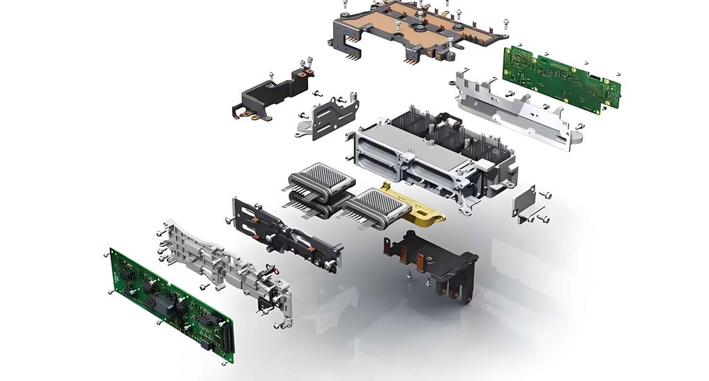
The automotive motor control unit system is a sophisticated integration of sensors, the motor control unit itself, and actuators. From my observations, each component plays a vital role in ensuring seamless engine operation. Sensors, such as throttle position sensors and air flow meters, continuously monitor parameters like engine speed and coolant temperature, converting physical data into electrical signals. These signals are fed into the motor control unit, which acts as the brain of the system. The motor control unit processes this information using predefined algorithms and sends commands to actuators, such as fuel injectors and spark plugs, to adjust engine functions like fuel injection and ignition timing. This closed-loop control mechanism, as I have often explained to trainees, ensures optimal performance under varying conditions. For instance, during idle, the motor control unit regulates air intake via the idle control valve based on sensor inputs, maintaining stable rpm. To illustrate this interplay, I find it helpful to summarize the components in a table, as shown below.
| Component Type | Examples | Primary Function | Role in System |
|---|---|---|---|
| Sensors | Throttle position sensor, air flow meter, crankshaft position sensor | Monitor engine parameters and convert to electrical signals | Provide real-time data to the motor control unit |
| Motor Control Unit | Electronic control unit (ECU) | Process sensor signals and generate control commands | Core processing unit for system coordination |
| Actuators | Fuel injectors, spark plugs, idle control valve | Execute commands to adjust engine operations | Implement adjustments based on motor control unit outputs |
The working principle of the motor control unit system hinges on feedback control theory, which I have applied in numerous diagnostic scenarios. In essence, the system operates through a continuous cycle: sensors collect data, the motor control unit analyzes it, and actuators respond to maintain engine stability. Mathematically, this can be represented using control equations. For example, the motor control unit often employs proportional-integral-derivative (PID) control to fine-tune parameters. The error signal \( e(t) \) between desired and actual values is computed, and the control output \( u(t) \) is adjusted as follows:
$$ u(t) = K_p e(t) + K_i \int_0^t e(\tau) d\tau + K_d \frac{de(t)}{dt} $$
Here, \( K_p \), \( K_i \), and \( K_d \) are tuning constants that the motor control unit optimizes for different driving conditions. This formula underscores the precision required in motor control unit operations, as even minor deviations can lead to performance issues. In practice, I have seen how the motor control unit dynamically adjusts fuel mixture ratios based on air flow sensor inputs, ensuring combustion efficiency. The process is summarized in the flowchart below, which I often use in workshops to explain the sequential steps involved.
Common faults in motor control unit systems can be categorized into several types, each with distinct symptoms and implications. Based on my field experience, actuator failures are frequent and disruptive. For instance, clogged fuel injectors or worn spark plugs can cause engine misfires, leading to vibrations and power loss. Similarly, sensor malfunctions, such as a faulty air flow meter, may result in inaccurate air-fuel mixtures, increasing fuel consumption and reducing engine output. The motor control unit itself, though robust, is not immune to issues; internal component damage or software glitches can cause erratic engine behavior or failure to start. Additionally, wiring problems, like frayed insulation or loose connectors, often interrupt signal transmission, creating intermittent faults that are challenging to diagnose. To aid in quick identification, I have compiled a table of typical faults and their effects, emphasizing the centrality of the motor control unit in each case.
| Fault Category | Specific Examples | Symptoms | Role of Motor Control Unit |
|---|---|---|---|
| Actuator Faults | Fuel injector blockage, spark plug wear | Engine抖动, acceleration issues, poor idle | Motor control unit may receive incorrect feedback or send ineffective commands |
| Sensor Faults | Air flow meter failure, throttle position sensor error | Inaccurate fuel mixture, hesitation during acceleration | Motor control unit relies on faulty data, leading to suboptimal control |
| Motor Control Unit Faults | Hardware damage, software corruption | Engine no-start, erratic performance, warning lights | Core processing unit compromised, affecting entire system |
| Wiring Faults | Short circuits, open circuits, corrosion | Intermittent signals, system shutdowns | Motor control unit cannot communicate properly with sensors/actuators |
Diagnosing faults in motor control unit systems requires a blend of advanced tools and hands-on expertise, as I have learned through trial and error. Instrument-based diagnosis is highly effective, utilizing devices like multimeters and oscilloscopes to measure electrical parameters. For example, when a wiring issue is suspected, I often use a multimeter to check for continuity or short circuits. If no current flows between two points, it indicates an open circuit, potentially due to broken wires; rapid needle swings suggest a short circuit, which might blow fuses. This method saves time and minimizes disassembly, but it has limitations—some subtle faults evade detection. Therefore, I complement it with manual diagnosis, relying on sensory observations like unusual noises or smells, coupled with experience-based reasoning. This approach demands deep knowledge of motor control unit behaviors, as I must interpret symptoms without relying solely on gadgets. Another technique I frequently employ is component substitution, where I replace suspected faulty parts with known good ones. If the issue resolves, the fault is confirmed; otherwise, I continue troubleshooting. This method is straightforward but requires a stock of spare parts and careful execution to avoid secondary damage. To streamline the diagnostic process, I have developed a decision matrix, shown below, that integrates these methods based on fault severity and accessibility.
| Method | Tools Required | Procedure | Advantages | Limitations |
|---|---|---|---|---|
| Instrument Diagnosis | Multimeter, oscilloscope, scan tool | Measure voltage, resistance, and signals at key points | Accurate, non-invasive, fast for electrical faults | May miss mechanical issues; requires technical skill |
| Manual Diagnosis | Basic tools, sensory assessment | Observe symptoms, check connections, apply experience | Flexible, cost-effective, good for subtle faults | Subjective, dependent on technician expertise |
| Component Substitution | Spare parts, diagnostic software | Swap suspected components and test system response | Direct confirmation, simple for isolated faults | Needs spare parts; risk of incorrect replacement |
Maintenance techniques for motor control unit systems are multifaceted, involving calibration, repair, and programming. From my practice, sensor calibration and replacement are critical first steps. When a sensor fails, I ensure the new unit matches the system specifications and securely connect all electrical plugs. After installation, calibration is essential—using diagnostic tools, I adjust the sensor output to align with actual engine conditions, ensuring the motor control unit receives accurate data. This process often involves mathematical adjustments, such as scaling sensor readings using a linear transformation: $$ V_{out} = m \cdot V_{in} + b $$ where \( V_{out} \) is the calibrated voltage, \( V_{in} \) is the raw sensor output, and \( m \) and \( b \) are calibration constants stored in the motor control unit. For actuators, I perform thorough inspections, disassembling units to check for wear or blockages. After repairs or replacements, debugging is crucial: I use scan tools to send test commands from the motor control unit and verify actuator responses, adjusting parameters as needed. This ensures seamless integration with the engine’s operational demands. The motor control unit itself may require hardware repairs, such as circuit board soldering, or software updates through reprogramming. In cases of software faults, I reflash the motor control unit with updated firmware, a task that demands precision to avoid bricking the unit. Wiring system maintenance involves testing continuity and insulation resistance, with repairs focusing on replacing damaged sections to restore reliable communication. Throughout these tasks, I emphasize the interconnectedness of components, as the motor control unit orchestrates the entire system. To illustrate common maintenance actions, I have prepared a table summarizing key procedures and their objectives.
| Component | Maintenance Action | Key Steps | Mathematical/Technical Basis |
|---|---|---|---|
| Sensors | Calibration and Replacement | Install new sensor, connect securely, calibrate using diagnostic tool | Linear calibration: $$ V_{cal} = a \cdot V_{raw} + c $$; ensures motor control unit gets accurate inputs |
| Actuators | 检修 and Debugging | Disassemble, inspect for damage, test with motor control unit commands, adjust parameters | PID tuning for actuator response: $$ u(t) = K_p e(t) + K_i \int e dt + K_d \frac{de}{dt} $$ |
| Motor Control Unit | Repair and Programming | Check circuits, replace faulty chips, reprogram software via OBD-II interface | Checksum verification: $$ C = \sum_{i=1}^{n} data_i \mod 256 $$; ensures firmware integrity |
| Wiring System | 检修 and Repair | Test continuity and insulation, replace damaged wires, secure connections | Ohm’s law: $$ R = \frac{V}{I} $$; used to identify short/open circuits |
Looking ahead, the field of motor control unit system diagnosis and maintenance is evolving toward greater automation and intelligence, trends I actively follow to stay current. In my view, the integration of artificial intelligence (AI) and machine learning will revolutionize fault detection, enabling predictive maintenance where the motor control unit analyzes data patterns to anticipate failures before they occur. For instance, AI algorithms can process sensor data in real-time, using models like neural networks to identify anomalies: $$ y = f\left(\sum_{i=1}^{n} w_i x_i + b\right) $$ where \( y \) is the fault probability, \( x_i \) are input features from the motor control unit, and \( w_i \) and \( b \) are learned weights. This reduces downtime and enhances safety. Additionally, one-touch diagnostic tools are becoming more prevalent, allowing quick scans that interface directly with the motor control unit to retrieve error codes and suggest repairs. I also foresee a shift toward systemic approaches, where the entire vehicle network, including the motor control unit, is monitored holistically for vulnerabilities. This aligns with the growing emphasis on cybersecurity, as modern motor control units are increasingly connected and need protection against hacking. Moreover, the use of digital twins—virtual replicas of engine systems—will enable simulation-based training and troubleshooting, reducing reliance on physical prototypes. As these technologies mature, I believe they will empower technicians to work more efficiently, but they will also require continuous learning to master new tools and concepts. The motor control unit, as the central hub, will remain pivotal in these advancements, driving innovation in automotive engineering.
In conclusion, my journey with automotive motor control unit systems has taught me that fault diagnosis and maintenance are complex yet rewarding disciplines, blending engineering principles with practical skills. The motor control unit stands at the core of these systems, orchestrating sensors and actuators to deliver optimal performance. By understanding common faults, applying robust diagnostic methods, and employing precise maintenance techniques, professionals can ensure vehicle reliability and safety. As technology advances, embracing trends like AI and automation will be essential for staying relevant in this dynamic field. I encourage fellow technicians to deepen their knowledge of the motor control unit, as it is the key to unlocking the full potential of modern automotive systems. Through ongoing education and hands-on experience, we can collectively drive the industry toward a future where vehicles are not only more efficient but also more resilient to failures.