
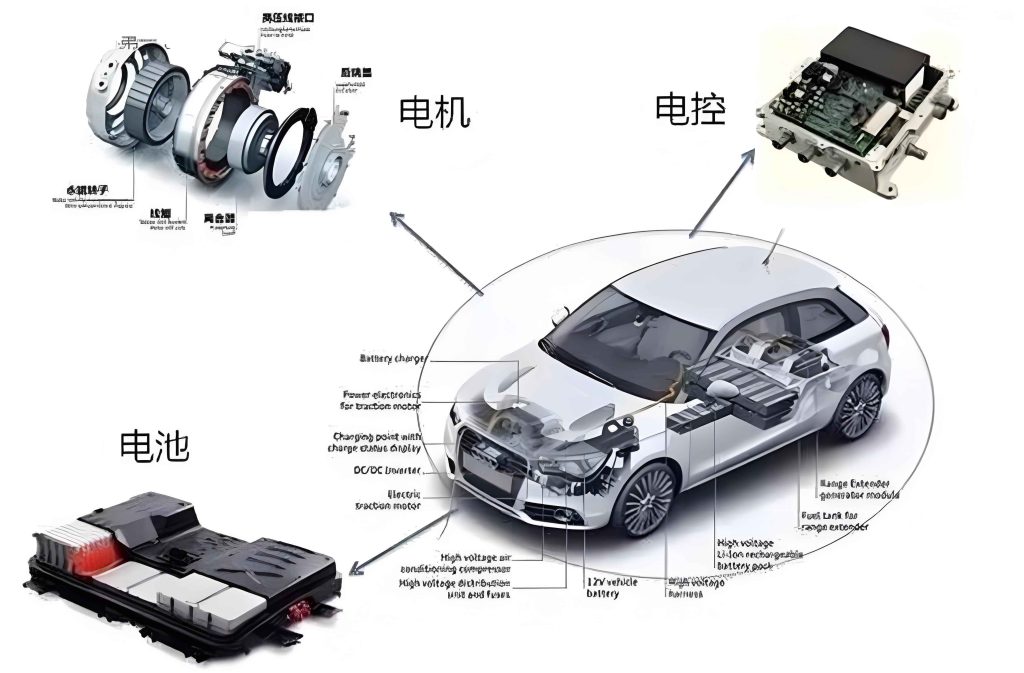
As the world increasingly prioritizes environmental sustainability, the new energy vehicle (NEV) industry has experienced rapid growth. In this context, I will delve into the electronic control system (ECS), which serves as the core component of NEVs. The ECS encompasses critical subsystems such as the battery management system, motor control unit, energy management system, charging management system, onboard communication system, and safety protection system. When faults occur within the ECS, they can significantly impair vehicle operation, leading to safety risks and reduced efficiency. Therefore, I believe it is essential to advance fault diagnosis technologies to enhance system reliability and performance. This article explores the composition of the NEV ECS, common faults, and state-of-the-art diagnosis techniques, with a focus on the motor control unit, which plays a pivotal role in vehicle dynamics.
The ECS in NEVs is a complex integration of multiple subsystems that work in concert to ensure efficient and safe vehicle operation. Below, I summarize the key components and their functions in a table to provide a clear overview.
| Component | Primary Function | Key Parameters Monitored |
|---|---|---|
| Battery Management System (BMS) | Monitors and manages battery state, including charge/discharge cycles, temperature, and voltage, to ensure safety and longevity. | Voltage, current, temperature, state of charge (SOC), state of health (SOH) |
| Motor Control Unit (MCU) | Controls the electric motor’s start/stop, speed, torque, and direction, enabling precise power output for vehicle propulsion. | Motor speed, torque, current, voltage, temperature |
| Energy Management System (EMS) | Optimizes energy flow between the battery, motor, and other components to maximize efficiency and range. | Power demand, energy distribution, regenerative braking efficiency |
| Charging Management System (CMS) | Manages the charging process, including speed, mode, and safety protocols, to prevent overcharging or overheating. | Charging current, voltage, time, battery temperature |
| Onboard Communication System (OCS) | Facilitates data exchange with external networks for remote monitoring, diagnostics, and infotainment. | Data transmission rate, signal strength, connectivity status |
| Safety Protection System (SPS) | Implements safeguards against faults such as overcurrent, short circuits, and thermal runaway to ensure vehicle safety. | Fault signals, system status, emergency shutdown triggers |
Among these, the motor control unit is particularly crucial, as it directly governs the vehicle’s acceleration, deceleration, and overall drivability. I will emphasize the motor control unit throughout this discussion, given its central role in NEV performance. The motor control unit processes inputs from various sensors to adjust motor operations, and any malfunction can lead to drivability issues or complete failure. For instance, a faulty motor control unit might cause erratic torque output, reduced efficiency, or overheating, which underscores the need for robust diagnosis techniques.
Common faults in the NEV ECS often stem from components like the battery, circuits, and electronic control units. I have categorized these faults based on their nature and impact, as shown in the following table. This classification aids in understanding the diagnostic challenges and targeting specific subsystems, including the motor control unit.
| Fault Category | Typical Symptoms | Potential Causes | Affected Subsystem |
|---|---|---|---|
| Power Battery Faults | Voltage drop, capacity degradation, thermal runaway, fire risk | Aging cells, manufacturing defects, improper charging | Battery Management System |
| Circuit Faults | Short circuits, open circuits, poor connections, signal loss | Wear and tear, corrosion, vibration, insulation failure | Entire ECS, especially motor control unit circuits |
| Electronic Control Unit Faults | System crashes, erroneous outputs, communication failures | Software bugs, hardware damage, electromagnetic interference | Motor Control Unit, Energy Management System, etc. |
| Motor-Related Faults | Overheating, abnormal noise, reduced torque, stalling | Bearing wear, winding faults, sensor malfunctions | Motor Control Unit and electric motor |
| Sensor Faults | Inaccurate readings, signal drift, complete failure | Physical damage, calibration errors, environmental factors | All subsystems relying on sensor data |
To address these faults, I explore various fault diagnosis technologies that leverage data analysis, artificial intelligence, and expert knowledge. The principles behind these technologies can be expressed mathematically to enhance precision. For example, fault diagnosis often involves probabilistic models or optimization algorithms. Consider a Bayesian approach to fault detection: $$ P(F|D) = \frac{P(D|F) P(F)}{P(D)} $$ where \( P(F|D) \) is the probability of a fault \( F \) given observed data \( D \), \( P(D|F) \) is the likelihood of data under fault conditions, \( P(F) \) is the prior probability of the fault, and \( P(D) \) is the evidence. This formula helps quantify uncertainty in diagnosis, particularly for intermittent faults in the motor control unit.
Another key technology is data analysis, which involves processing signals from sensors to extract fault features. I often use time-series analysis or frequency-domain methods. For instance, the Fourier transform can identify anomalies in motor control unit signals: $$ X(f) = \int_{-\infty}^{\infty} x(t) e^{-i 2\pi f t} dt $$ where \( x(t) \) is the time-domain signal (e.g., motor current), and \( X(f) \) reveals frequency components indicative of faults like bearing wear or imbalance. By monitoring these features, I can detect early signs of motor control unit degradation.
Expert systems represent a rule-based approach to diagnosis. I implement these systems using if-then rules derived from domain knowledge. For example, for the motor control unit, a rule might be: IF motor temperature exceeds 100°C AND torque output is erratic, THEN diagnose as cooling system fault. These systems are effective for known fault patterns but may struggle with novel issues. To overcome this, I integrate expert systems with machine learning techniques, such as artificial neural networks (ANNs). An ANN model for fault classification can be described as: $$ y_k = g\left(\sum_{j=1}^{m} w_{kj} \cdot h\left(\sum_{i=1}^{n} w_{ji} x_i + b_j\right) + b_k\right) $$ where \( x_i \) are input features (e.g., sensor data from the motor control unit), \( w \) and \( b \) are weights and biases, \( h \) and \( g \) are activation functions, and \( y_k \) represents the fault class output. This allows adaptive learning from historical data, improving diagnosis accuracy for complex ECS faults.
Fuzzy logic diagnosis is another method I employ, especially when dealing with imprecise data. It uses membership functions to handle vague concepts like “high temperature” or “low voltage.” For the motor control unit, I might define a fuzzy rule: IF speed error is large AND current fluctuation is moderate, THEN fault likelihood is high. The inference process can be formalized as: $$ \mu_{output}(z) = \max \left[ \min(\mu_{A}(x), \mu_{B}(y)) \right] $$ where \( \mu \) denotes membership degrees, and \( z \) is the diagnosis outcome. This approach is robust in real-world scenarios where sensor noise is present.
Genetic algorithms (GAs) offer an optimization-based diagnosis technique. I use GAs to search for optimal fault parameters by mimicking natural selection. The fitness function in a GA for motor control unit fault diagnosis might be: $$ F = \frac{1}{1 + \sum_{i=1}^{n} (y_i – \hat{y}_i)^2} $$ where \( y_i \) are actual observations, and \( \hat{y}_i \) are model predictions. By evolving solutions over generations, GAs can identify subtle faults that traditional methods miss.
In practice, I combine multiple technologies for comprehensive diagnosis. The following table summarizes the key fault diagnosis technologies, their applications, and advantages, with a focus on the motor control unit.
| Diagnosis Technology | Core Methodology | Application in ECS | Advantages |
|---|---|---|---|
| Fault Code Diagnosis | Analyzes diagnostic trouble codes (DTCs) from onboard systems using standardized protocols. | Quick identification of known faults in motor control unit and other modules. | Fast, standardized, requires minimal computation. |
| Data Analysis Technology | Processes real-time sensor data (e.g., via CAN bus) to detect anomalies and trends. | Continuous monitoring of motor control unit parameters like current and temperature. | Real-time capability, early fault detection. |
| Fault Mode Recognition | Uses pattern recognition (e.g., ANNs, support vector machines) to classify fault types. | Distinguishing between different motor control unit faults based on historical data. | High accuracy, handles complex patterns. |
| Expert Systems | Applies rule-based reasoning from human expertise to diagnose faults. | Guided troubleshooting for motor control unit issues based on symptom rules. | Transparent logic, easy to update with new rules. |
| Fuzzy Logic Diagnosis | Employs fuzzy sets to manage uncertainty in fault indicators. | Assessing vague symptoms like “slight overheating” in motor control unit. | Robust to noise, mimics human reasoning. |
| Genetic Algorithm Diagnosis | Optimizes fault parameters through evolutionary algorithms. | Fine-tuning diagnosis models for motor control unit under varying conditions. | Global optimization, adapts to new scenarios. |
To illustrate the integration of these technologies, I consider a case study on motor control unit fault diagnosis. The motor control unit relies on precise control algorithms, such as field-oriented control (FOC), which can be modeled mathematically. The FOC equations for an AC motor are: $$ i_d = \frac{2}{3} \left( i_a \cos \theta + i_b \cos \left(\theta – \frac{2\pi}{3}\right) + i_c \cos \left(\theta + \frac{2\pi}{3}\right) \right) $$ $$ i_q = -\frac{2}{3} \left( i_a \sin \theta + i_b \sin \left(\theta – \frac{2\pi}{3}\right) + i_c \sin \left(\theta + \frac{2\pi}{3}\right) \right) $$ where \( i_d \) and \( i_q \) are direct and quadrature currents, \( i_a, i_b, i_c \) are phase currents, and \( \theta \) is the rotor angle. Deviations from expected values in these currents can indicate faults in the motor control unit or motor itself. By applying data analysis techniques, I monitor these parameters and use ANNs to classify faults, such as inverter switch failures or sensor drifts.
Furthermore, I emphasize the importance of the motor control unit in overall system health. The motor control unit not only controls propulsion but also interacts with other subsystems. For instance, during regenerative braking, the motor control unit coordinates with the energy management system to recharge the battery. Faults here can reduce energy recovery efficiency. Therefore, I propose a holistic diagnosis framework that considers cross-system dependencies. This framework can be represented as a weighted graph model: $$ G = (V, E, w) $$ where vertices \( V \) represent subsystems (e.g., motor control unit, BMS), edges \( E \) represent interactions, and weights \( w \) denote fault propagation probabilities. By analyzing this graph, I can prioritize diagnostics for critical components like the motor control unit.
In terms of implementation, I recommend using onboard and offboard tools. Onboard systems continuously log data from the motor control unit and other components, while offboard tools perform deep analysis using cloud computing. For example, I might upload motor control unit data to a cloud platform where machine learning models diagnose faults and suggest repairs. This leverages the onboard communication system for remote diagnostics, enhancing convenience and reducing downtime.
Looking ahead, I believe advancements in artificial intelligence will revolutionize NEV ECS fault diagnosis. Deep learning models, such as convolutional neural networks (CNNs), can process raw sensor data from the motor control unit without extensive feature engineering. A CNN for time-series fault detection might use the formula: $$ \mathbf{H} = \sigma(\mathbf{W} * \mathbf{X} + \mathbf{b}) $$ where \( \mathbf{X} \) is the input data matrix, \( \mathbf{W} \) is the filter kernel, \( * \) denotes convolution, \( \mathbf{b} \) is the bias, and \( \sigma \) is the activation function. This enables automatic feature extraction, improving diagnosis speed and accuracy for motor control unit faults.
In conclusion, I have explored the composition, common faults, and diagnosis technologies for NEV electronic control systems, with repeated emphasis on the motor control unit due to its critical role. By integrating methods like data analysis, expert systems, fuzzy logic, ANNs, and genetic algorithms, I can enhance fault detection and system reliability. As NEVs evolve, continued research into these technologies will be vital for ensuring safety, efficiency, and sustainability. The motor control unit, as a central component, demands particular attention in this endeavor, and I am confident that innovative diagnosis approaches will drive the future of smart mobility.