
In this research, I systematically investigated the passive control method for thermal runaway propagation of a vehicle traction battery. The main objective was to design and verify an effective insulation structure that can prevent the thermal spread from a failed lithium-ion cell to adjacent healthy cells under thermal abuse conditions. I focused on the commercial 18650 cylindrical lithium-ion vehicle traction battery with a nickel-cobalt-aluminum oxide cathode and graphite anode. Through combined experimental and numerical approaches, I first analysed the thermal runaway characteristics of a single cell, then evaluated the thermal barrier performance of ceramic-fiber silica aerogel composites with different thicknesses, and finally proposed an optimized three-layer insulation structure with improved thermal isolation capability. Throughout the study, the issue of protecting the vehicle traction battery from cascading thermal events was considered from both thermal resistance and practical engineering perspectives.
The rapid development of electric vehicles has made the safety of the vehicle traction battery one of the most critical topics in the automotive industry. The high energy density of the lithium-ion battery brings significant advantages in driving range, but it also presents serious hazards under extreme abuse conditions. When a single cell undergoes thermal runaway, a large amount of heat is released in a very short time, triggering the ignition and explosion of the whole battery pack. This cascading failure is particularly dangerous for a vehicle traction battery because the compact arrangement of cells facilitates thermal propagation. Therefore, effective suppression strategies are urgently needed. Active cooling systems such as liquid nitrogen and water mist are effective but difficult to integrate into a sealed vehicle traction battery pack. Passive thermal barriers, on the other hand, offer a compact and maintenance-free solution. Among many insulating materials, silica aerogel composites have attracted my attention due to their ultra-low thermal conductivity and excellent fire resistance. The aim of my investigation was to determine the optimum thickness of such a barrier and to develop an upgraded structure that provides greater protection without adding excessive volume or mass to the vehicle traction battery system.
I designed a series of experiments using a high-temperature heating rod to simulate the thermal abuse condition. The battery under test was fully charged to 100% state of charge. Three K-type thermocouples were attached to the battery surface near the heating side at the top, middle and bottom positions to record the temperature evolution. Another thermocouple was attached in the middle of the heating rod to monitor the heat source temperature. The voltage of the cell was continuously measured by a high-precision digital multimeter. All measurements were placed in a constant temperature chamber at 27 °C, while a thermal imaging camera recorded the process through an observation window. I carefully calibrated the thermocouples before each experiment and repeated several cases to ensure repeatability. The experimental platform allowed precise positioning of the battery, the heating rod and the insulation layer. I also performed control experiments to compare the difference between unprotected and protected configurations. These experiments were all performed on the vehicle traction battery cells to ensure real-world relevance.
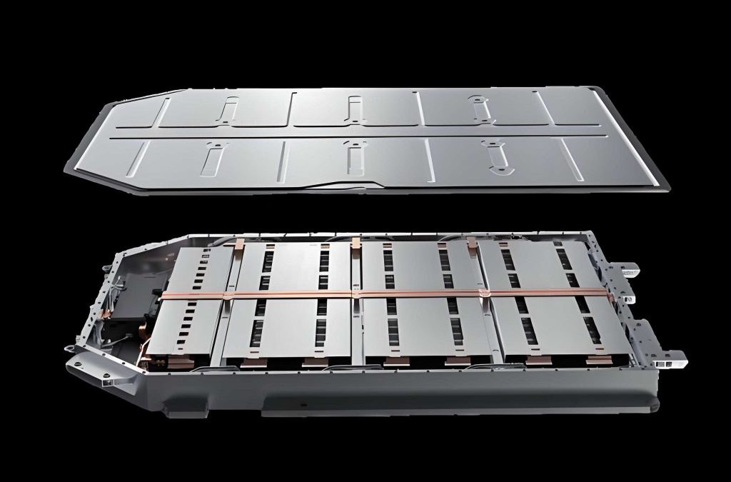
1. Thermal Runaway Experiment of the Vehicle Traction Battery
I first performed a thermal runaway experiment on a single 18650 vehicle traction battery without any protective layer. The battery was charged to 4.2 V using a constant current constant voltage protocol, then heated with the heating rod at a rated power of 350 W. The heating rod was placed in direct contact with the battery surface. I recorded the surface temperature and open-circuit voltage until the battery entered thermal runaway. The measured temperature data show that the thermal runaway process can be divided into four distinct stages. The first stage was the continuous heating stage, during which the battery temperature rose steadily due to the externally imposed heat. The voltage remained almost stable with a fluctuation of only about 0.01 V. When the surface temperature reached 190.74 °C, an internal short circuit was triggered, marking the beginning of the second stage. The voltage suddenly dropped and fluctuated around a low value. At a temperature of 219.13 °C, the safety valve opened, which was the third stage. At that instant, the voltage fell to nearly zero and a visible flame appeared at the positive terminal. Finally, the fourth stage was the fully developed thermal runaway, which occurred at 243.4 °C after 494 seconds of heating. Within two or three seconds, a violent jet flame was ejected from the battery positive terminal. The maximum surface temperature reached 786.41 °C and the largest temperature rise rate exceeded 167.88 °C/s. This process is extremely fast and intense, confirming the severity of thermal runaway in a high-energy vehicle traction battery. In one repetitive experiment, the battery even exploded from the side shell rather than only ejecting from the vent, showing that the failure mode can be random and creates a more severe hazard for neighboring cells.
The thermal runaway of the vehicle traction battery is driven by a series of exothermic chemical reactions. At elevated temperatures, the solid electrolyte interphase begins to decompose, exposing the negative electrode to the electrolyte. The subsequent reaction between the intercalated lithium and the solvent generates more heat. When the separator melts, a large-area internal short circuit occurs, which immediately raises the cell temperature. The cathode material then decomposes and releases oxygen, while the electrolyte undergoes further oxidation and combustion. These reactions are highly interlinked. I summarized the major reaction steps in my analysis and used them to interpret the temperature and voltage signatures. The important observation is that once the internal short circuit occurs, the remaining time to thermal runaway is only about 89 seconds. Therefore, an effective thermal barrier for the vehicle traction battery must prevent the external cell temperature from ever reaching the internal short circuit threshold during a prescribed abuse period.
2. Theoretical Background and Thermal Analysis
The fundamental heat transfer mechanisms in the thermal spread process include conduction, convection and radiation. Conduction follows Fourier’s law:
$$\Phi = -\lambda A \frac{dT}{dx}.$$
The convective heat transfer from the hot surfaces to the surrounding air is expressed by Newton’s law of cooling:
$$\Phi = h A \Delta T.$$
The radiative heat exchange between the heating rod, the insulation and the battery surface obeys the Stefan–Boltzmann law:
$$\Phi = \varepsilon A \sigma T^4.$$
These mechanisms determine how heat is transmitted from a thermally failed cell to the neighboring cells in a vehicle traction battery module. I used computational fluid dynamics to resolve the coupled flow and temperature fields during the heating process. The governing equations in the simulations were the mass conservation equation:
$$\frac{\partial \rho}{\partial t} + \nabla\cdot(\rho \vec{u}) = 0,$$
the momentum conservation equation, and the energy conservation equation. For the turbulent natural convection generated by the high temperature gradients, I employed the Realizable \(k-\varepsilon\) model. The transport equations for the turbulent kinetic energy \(k\) and dissipation rate \(\varepsilon\) are given by:
$$\frac{\partial (\rho k)}{\partial t} + \frac{\partial(\rho k u_j)}{\partial x_j} = \frac{\partial}{\partial x_j}\left[\left(\mu+\frac{\mu_t}{\sigma_k}\right)\frac{\partial k}{\partial x_j}\right] + G_k – \rho \varepsilon,$$
$$\frac{\partial (\rho \varepsilon)}{\partial t} + \frac{\partial(\rho \varepsilon u_j)}{\partial x_j} = \frac{\partial}{\partial x_j}\left[\left(\mu+\frac{\mu_t}{\sigma_\varepsilon}\right)\frac{\partial \varepsilon}{\partial x_j}\right] + \rho C_1 E \varepsilon – \rho C_2 \frac{\varepsilon^2}{k+\sqrt{\nu \varepsilon}}.$$
The thermal runaway internal side reactions can be approximated by the Arrhenius law. The decomposition of the SEI film, the reaction between the negative electrode and electrolyte, the cathode decomposition and the electrolyte reaction all contribute to the exothermic heat. I used the lumped models in my simulation but neglected the chemical heat generation when the battery temperature was below 120 °C, because in that temperature range the produced heat is small compared with the external heating power, especially for a vehicle traction battery with a relatively small surface area.
The lithium-ion battery consists of a positive electrode, a negative electrode, an electrolyte, a separator and current collectors. The working principle is based on the migration of lithium ions between the electrodes during charge and discharge. The positive electrode material used in my experiments was LiNi0.8Co0.15Al0.05O2, commonly referred to as NCA. The thermal stability of NCA is lower than that of lithium iron phosphate, which makes the battery more vulnerable to thermal runaway. In a vehicle traction battery, the cell temperature must remain below the onset temperature of the internal decomposition reactions. I therefore chose a maximum acceptable surface temperature as the design threshold based on the measured internal short circuit temperature. From the baseline experiment, the internal short circuit occurred at a surface temperature of 190.74 °C. I conservatively selected 142.1 °C, which was the surface temperature 100 seconds before the internal short circuit, as the safety criterion for the insulation layer design. That selection guarantees a sufficient margin against both measurement uncertainties and possible cell differences in a real vehicle traction battery pack.
3. Single-Layer Insulation Structure for Thermal Spread Control
After establishing the baseline thermal runaway behavior, I investigated the passive control of thermal spread using ceramic-fiber silica aerogel composite boards. These boards were provided by a manufacturer with thickness options ranging from 1.5 mm to 5 mm. The aerogel composite has an extremely low thermal conductivity of 0.023 W/m·K at room temperature and 0.036 W/m·K at 300 °C. It also has a high combustion rating and a hydrophobic rate of 98%. In the thermal spread control experiment, the insulation board was placed between the heating rod and the vehicle traction battery, with all three components in direct physical contact. The heating power was set to 350 W and the heating duration was fixed at 1200 seconds unless thermal runaway occurred earlier. I selected the safety factor of 2.4 based on the baseline runaway time of about 494 seconds, meaning that if the battery remained safe after 1200 seconds of continued heating, the insulation was regarded as effective.
I first tested the thinnest available board with a thickness of 1.5 mm. The measured temperature curves show that the battery still underwent thermal runaway after about 851 seconds of heating. Nevertheless, compared with the unprotected case, the occurrence of thermal runaway was delayed by 357 seconds. The internal short circuit, safety valve opening and thermal runaway temperatures were very close to those in the unprotected baseline, indicating that the failure mechanism did not charge even with the thin insulation. The main effect of the 1.5 mm aerogel was to reduce the rate of temperature rise. The average temperature rise rate between 200 seconds and the onset of thermal runaway decreased to less than 0.3 °C/s. This showed that a thin aerogel layer can prolong the safe time window but it cannot completely prevent thermal runaway in a vehicle traction battery under such a severe heating condition.
In the next experiment I tested the thickest available board with a thickness of 5 mm. During the entire 1200 seconds of heating, the battery surface temperature remained below about 120 °C and the voltage was almost constant. No internal short circuit was detected. The temperature rise rate first increased and then gradually decreased, reaching a maximum of only 0.403 °C/s. This demonstrated that the 5 mm silica aerogel board could successfully stop the thermal spread and keep the vehicle traction battery in a safe state. I also compared the average temperature rise rates over 50-second intervals between the 1.5 mm and 5 mm groups. The 5 mm board clearly provided a stronger thermal isolation capability. With these results I concluded that a single aerogel layer can be an effective passive control method, but the optimum thickness must be determined to avoid unnecessary volume and weight while ensuring safety.
4. Numerical Simulation and Optimization of the Insulation Thickness
In order to find the minimum thickness that still protects the vehicle traction battery, I built a three-dimensional computational fluid dynamics model. The geometry included the heating rod, the silica aerogel board and the 18650 cell, all placed in the same relative configuration as in the experiments. The computational domain was a cube with a side length of 0.5 m, representing the interior of the constant temperature chamber. The air was modeled as an ideal gas with temperature-dependent properties. The metal heating rod was considered a solid with a constant heat source of 350 W. The battery was modeled as a solid with anisotropic thermal conductivities: 0.413 W/m·K in the radial direction and 1.780 W/m·K in the axial direction. The density and specific heat were taken from experimental data for the NCA 18650 vehicle traction battery. The surface emissivity of the battery was set to 0.9. The silica aerogel was modeled as an isotropic solid with a density of 300 kg/m³, a specific heat of 774 J/kg·K, and a temperature-dependent thermal conductivity.
I generated polyhedral volume meshes with ten prismatic boundary layers near the solid surfaces. To verify mesh independence, I compared seven different mesh sizes from about 0.86 million to 8.28 million cells. I selected three monitoring points on the battery surface at the same height as in the experiment. The maximum relative difference in the predicted temperatures between the model with 3.04 million cells and the model with 8.28 million cells was less than 0.4‰, confirming that the solution was mesh independent. I finally used a mesh of approximately 5.59 million cells for all subsequent simulations. The time step was 0.1 seconds with five iterations per time step, and the total computed time was 1200 seconds. The simulation results for the 5 mm aerogel insulation were compared with the measured experimental data. The overall temperature rise profile was well reproduced, with a maximum error of 5.6%.
After validating the numerical model, I simulated the heating process for aerogel thicknesses from 1.7 mm to 5.0 mm in increments of 0.3 mm. I recorded the maximum battery surface temperature near the heating side at the end of the 1200-second heating period. The values are summarized in the following table.
| No. | Aerogel thickness (mm) | Maximum battery surface temperature (°C) |
|---|---|---|
| 1 | 5.0 | 133.60 |
| 2 | 4.7 | 135.60 |
| 3 | 4.4 | 137.90 |
| 4 | 4.1 | 140.20 |
| 5 | 3.8 | 144.00 |
| 6 | 3.5 | 149.60 |
| 7 | 3.2 | 155.50 |
| 8 | 2.9 | 166.10 |
| 9 | 2.6 | 185.00 |
| 10 | 2.3 | 204.90 |
| 11 | 2.0 | 225.68 |
| 12 | 1.7 | 247.80 |
Using the simulated data points, I fitted a polynomial relationship between the maximum temperature \(T_{max}\) and the aerogel thickness \(x\):
$$T_{max} = -2.445 x^3 + 38.87 x^2 – 206.4 x + 500.8,$$
with a coefficient of determination \(R^2 = 0.9975\). By substituting the discrete thicknesses available from the manufacturer, I obtained the corresponding maximum temperatures. The available thickness values were 1.5 mm, 2 mm, 3 mm, 4 mm and 5 mm. I decided to select the 4 mm thick aerogel because it gave a predicted battery surface temperature of 140.64 °C, which is just below the safety criterion of 142.1 °C. Thinner options were clearly unsafe, while 5 mm would be unnecessarily heavy. I then performed an additional simulation and an experiment with the 4 mm board. The simulated maximum temperature was 137.82 °C and the experimental maximum temperature was about 142.1 °C, both proving that the 4 mm layer can protect the vehicle traction battery under the tested thermal abuse condition.
5. Thermal Isolation Performance of the Selected Single-Layer Insulation
I further analyzed the thermal and flow fields from the simulation using the 4 mm aerogel. The temperature contours on the battery surface and the aerogel surface at 1200 seconds show that the battery temperature distribution was highly non-uniform. The radial heat conduction inside the cylindrical vehicle traction battery is quite low, so the temperature difference between the heated side and the opposite side exceeded 70 °C. In the vertical direction, the natural convection of air heated by the rod made the upper part of the battery slightly hotter than the lower part. The boundary heat flux was concentrated in the region directly opposite the heating rod. The heat flux at the middle positions was much larger than that near the lateral edges.
The streamline visualization illustrates the formation of natural convection loops in the computational domain. Heated air rises from the heating rod and the aerogel surfaces, reaches the top of the domain, spreads horizontally, then descends along the side walls and returns to the bottom. The maximum instantaneous air velocity in the entire domain was about 0.64 m/s. I also examined the velocity magnitude on a horizontal plane at the mid-height of the battery at different times from 50 s to 200 s. At 200 seconds, the maximum velocity on the heating rod side was about 0.4 m/s, while on the battery side it was only about 0.14 m/s. This difference is caused by the strong thermal insulation of the aerogel, which reduces the air temperature near the battery and thus suppresses the buoyancy-driven flow. The maximum velocity on the battery side was only about 35% of that on the heating rod side at that time. These results show that the passive insulation structure not only reduces conductive heat transfer but also significantly attenuates convective heat transport around the protected vehicle traction battery.
6. Application in a Vehicle Traction Battery Module
To demonstrate the feasibility of the 4 mm aerogel layer in a realistic vehicle traction battery pack, I extended the simulation to a 3×3 battery module. The cells were arranged with a center-to-center spacing of 24 mm. A single 4 mm thick aerogel board was placed between each adjacent row of cells. The heating rod was placed in three different positions: at the center of the module, at one corner, and at the side. In the center case, the heating rod was surrounded by four aerogel boards and eight cells. In the corner case, the rod was inserted at one diagonal corner, and in the side case it was placed outside one side. I monitored the maximum surface temperature of each cell during the 1200-second heating period. The results show that the maximum surface temperature of the closest cells was around 133 °C to 134 °C for all three configurations, below the safe threshold. Cells farther away experienced much lower temperatures. For example, in the corner configuration, the farthest cell reached only about 28.3 °C, which is only slightly above ambient temperature. The following table summarizes the maximum temperatures of representative cells in each case.
| Case | Cell No. | Maximum temperature (°C) |
|---|---|---|
| Center | Cell 1 | 60.18 |
| Center | Cell 2 | 133.55 |
| Corner | Cell 1 | 28.30 |
| Corner | Cell 4 | 30.65 |
| Corner | Cell 5 | 59.98 |
| Corner | Cell 7 | 35.17 |
| Corner | Cell 8 | 133.73 |
| Side | Cell 1 | 134.31 |
| Side | Cell 3 | 60.08 |
| Side | Cell 4 | 132.65 |
| Side | Cell 6 | 30.69 |
| Side | Cell 7 | 34.69 |
The temperature contours in the horizontal plane of the module show a clear temperature drop across each aerogel board. The thermal insulation layer creates a large temperature difference between the heated side and the protected side. The aerogel boards are therefore capable of preventing cascading thermal runaway propagation in a vehicle traction battery. I also visualized the flow streamlines in the module. The air heated by the central heating rod rises rapidly, while the surrounding air circulates more gently near the cells. The low velocity in the protected zones reduces the convective heat load on the cells, contributing to the overall safety of the battery module.
7. Optimized Three-Layer Insulation Structure
Although the single aerogel layer can protect the vehicle traction battery, I aimed to further improve its thermal isolation performance without adding a large thickness. I proposed a three-layer structure in which a 4 mm thick silica aerogel core is sandwiched between two thin metal sheets. The metal sheets have very low surface emissivity compared with the white aerogel surface. They can reflect a large portion of the radiative heat back toward the heat source, thereby reducing the amount of radiation impinging on the aerogel core. Since the aerogel already has an extremely low thermal conductivity, the metal sheets mainly affect the radiative transfer. This design is particularly effective because at high temperatures radiation becomes the dominant heat transfer path in open air. I first tested copper sheets of different thicknesses: 0.1 mm, 0.2 mm, 0.3 mm and 0.4 mm. The metal sheets were bonded to the aerogel plates with a high-temperature silicone adhesive. In this series of tests, I did not attach the battery. Instead, I placed the three-layer board in contact with the heating rod and measured the temperature on the back side of the board with three thermocouples. After 1200 seconds, the heating rod surface temperature had stabilized at about 632 °C. The temperature rise curves show that all four copper thicknesses provided similar performance, with the 0.2 mm, 0.3 mm and 0.4 mm sheets giving nearly identical results. The 0.1 mm sheet was slightly worse because it oxidized more rapidly at high temperature. The oxidized copper surface has a much higher emissivity than the polished copper, which diminishes its radiative reflection capability. Considering both thermal performance and total weight, I selected 0.2 mm copper as the optimal metal layer thickness.
In the next stage, I compared four different metal materials with the same 0.2 mm thickness: copper, tungsten, iron and Inconel 718. I performed two types of experiment for each material: a back-side temperature measurement and a thermal spread control test with a fully charged 18650 vehicle traction battery. The back-side temperature results show that copper and tungsten had very similar final temperatures, with average temperatures of 151.4 °C and 151.6 °C during the final 100 seconds. Iron gave a slightly higher final temperature of about 162.6 °C, while Inconel 718 stabilized at about 154.4 °C. In the full thermal spread control experiments, all four three-layer structures prevented the battery from experiencing thermal runaway during the 1200-second heating period. The maximum battery surface temperatures at the end of heating were 91.59 °C for copper, 98.3 °C for tungsten, 101.24 °C for iron and 100.53 °C for Inconel 718. The copper-based three-layer structure clearly provided the best thermal protection for the vehicle traction battery. Compared with the single-layer aerogel structure, the three-layer structure with copper sheets reduced the maximum battery surface temperature by 39.18 °C, which corresponds to a 29.96% reduction. The voltage of the battery in this experiment remained almost unchanged throughout the heating process, confirming that no internal short circuit occurred.
The mechanism behind the improved performance can be explained by considering the radiative reflection from the metal surfaces. The emissivity of polished copper is as low as 0.03, while the emissivity of the white silica aerogel composite is about 0.794. According to Kirchhoff’s law, the absorptivity of a surface is equal to its emissivity under the same temperature and wavelength conditions. Thus the copper sheet absorbs only a small fraction of the incoming infrared radiation. Most of the thermal radiation emitted by the heating rod is reflected back to the hot side. Consequently, the heat flux entering the aerogel core is substantially reduced. In addition, the metal sheets act as radiation shields and create a highly non-symmetric radiative transfer environment. The central aerogel core then further suppresses any remaining conductive heat transfer. My simulations and experiments consistently indicate that this three-layer laminated structure is a promising passive thermal barrier for a vehicle traction battery pack. However, I noticed that the metal sheets add a significant weight penalty. For an insulation area of 90 mm × 90 mm, two 0.2 mm copper sheets weigh about 29.03 g, whereas the 4 mm thick silica aerogel core weighs only 9.72 g. The total mass of the three-layer structure is 38.75 g, which is about 298.7% heavier than the single aerogel layer. In future work it will be desirable to use lighter metal alloys or thinner coatings that can still maintain low emissivity and high oxidation resistance.
8. Concluding Remarks and Future Perspective
In this research, I experimentally captured the thermal runaway behavior of an 18650 lithium-ion vehicle traction battery and identified the critical temperatures for internal short circuit, safety valve opening and full thermal runaway. The maximum surface temperature exceeded 786 °C and the temperature rise rate reached 167.88 °C/s, indicating an extremely fast and hazardous event. I then demonstrated that ceramic-fiber silica aerogel composites can act as effective passive thermal barriers for the vehicle traction battery. By combining experiments with numerical simulations, I determined the optimal single-layer thickness to be 4 mm for the tested condition. This layer successfully maintained the battery surface temperature below the safety threshold during a 1200-second heating period. The simulation also revealed the flow field characteristics and the spatial temperature non-uniformity around the protected cell. I extended the simulation to a 3×3 module and showed that the same insulation layer can stop thermal runaway propagation in different heating locations. Finally, I designed and tested a three-layer structure consisting of copper sheets and a silica aerogel core. This structure achieved a 29.96% reduction in the maximum battery surface temperature compared with the single aerogel layer, while adding only 0.4 mm of extra thickness. The improved performance was attributed mainly to the low surface emissivity of the copper sheets, which reflect radiative heat back to the source. Although my study focuses on the cell-level passive protection, the results provide a solid basis for designing thermal runaway propagation barriers in future vehicle traction battery systems. I plan to further investigate the long-term durability of the metal sheets under cyclic thermal loading and to validate the protection concept in a large-scale battery pack under realistic vehicle crash and thermal abuse scenarios.