
In my research, I focus on the modeling and control of multi-functional air conditioning systems for battery electric vehicles. The electric vehicle market has experienced explosive growth around the world, and China has become the largest producer and consumer of electric vehicles. In 2025, the national production and sales of new energy vehicles reached 16.6 million and 16.5 million units, respectively. The continued growth of the electric vehicle fleet poses new challenges for thermal comfort, energy consumption, and intelligent cabin management. Among all auxiliary systems in an electric vehicle, the air-conditioning system is one of the largest energy consumers. In a conventional internal combustion engine vehicle, waste heat from the engine is available for cabin heating, and the compressor is mechanically driven by the engine. In a battery electric vehicle, however, the entire air-conditioning system relies on the high-voltage battery. This fundamental difference emphasizes the need to develop efficient and intelligent air-conditioning architectures and control strategies for electric vehicles.
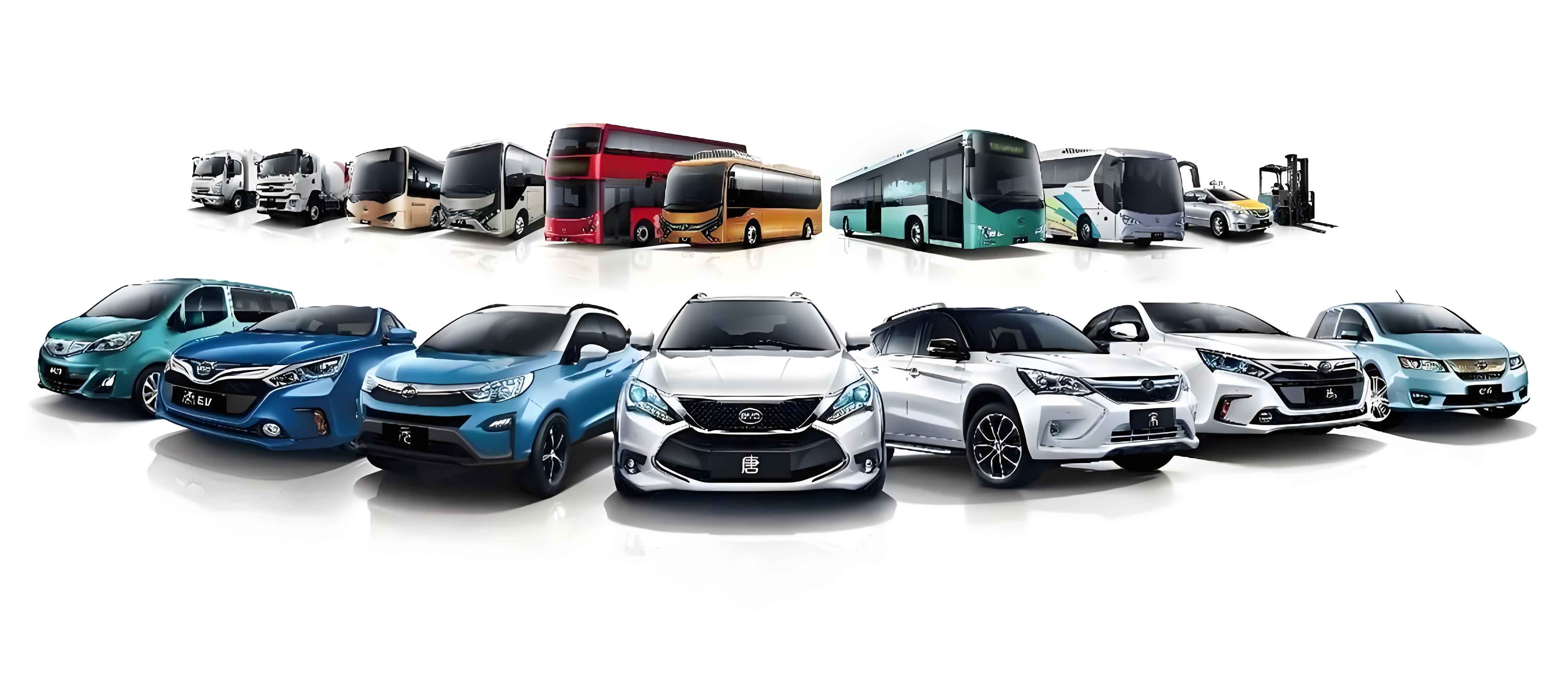
The evolution of automotive technology has shifted toward electrification, connectivity, intelligence, and shared mobility. Users of electric vehicle air-conditioning systems increasingly demand not only accurate temperature regulation, but also personalized comfort, remote operation, air-quality management, and low energy consumption. Traditional manual controllers can no longer satisfy these requirements. Therefore, my work intends to establish a systematic framework for an electric vehicle multi-functional air-conditioning system, which combines an efficient vapor-compression heat pump cycle with embedded intelligent control functions. This framework includes dynamic modeling, control algorithm design, embedded system development, and real-vehicle validation.
2. Literature Review and Contributions
I reviewed extensive prior studies on air-conditioning systems for electric vehicles. Early research on vehicle thermal management focused on conventional internal combustion engines. With the rapid adoption of battery electric vehicles, researchers have redirected their attention to heat-pump air-conditioning systems because heat pumps provide higher heating efficiency than electric positive temperature coefficient heaters. Several studies confirmed that heat-pump systems can increase the driving range of an electric vehicle during winter by reducing cabin-heating energy consumption. In the field of control, proportional-integral-derivative controllers are widely used because of their simple structure and robustness. However, the heating, ventilation, and air-conditioning system of an electric vehicle is a strongly nonlinear, time-varying, and multivariable system. Conventional PID controllers tuned at one operating point may exhibit degraded performance under a wide range of ambient temperatures and dynamic driving conditions. Researchers have therefore proposed fuzzy logic control, model predictive control, adaptive control, and neural-network control to improve transient response and disturbance rejection. Fuzzy PID control, in particular, combines the intuitive rule-based reasoning of fuzzy logic with the linear regulation capability of PID controllers.
For electric vehicles, cabin comfort must be balanced with battery temperature management. Modern electric vehicle architectures integrate the passenger-compartment heat pump loop with a cooling/heating circuit for the high-voltage battery. The use of an internal heat exchanger offers an effective means of increasing the coefficient of performance and the stability of the thermodynamic cycle. In addition, multi-functional cabin control is becoming a differentiator in electric vehicle products. Predictive cabin preconditioning, dual-zone or tri-zone temperature control, driver-fatigue assistance, call-noise suppression, intelligent air recirculation, negative-ion air purification, and remote ventilation are desirable functions. These functions require high-performance electronic controllers designed under automotive open system architecture standards. My research contributes to this field by developing a verified electric vehicle heat-pump air-conditioning model incorporating an internal heat exchanger, designing a fuzzy PID control algorithm, implementing the controller hardware and software, and validating the complete system on a real electric vehicle platform.
3. Modeling and Analysis of an IHX Heat-Pump Air-Conditioning System
3.1 System Structure and Working Principle
In my research, the baseline system is an air-conditioning circuit that comprises an electric compressor, an outdoor heat exchanger, an indoor evaporator, a water-cooled condenser, expansion valves, a liquid/vapor separator, chillers for battery cooling, and an internal heat exchanger. The internal heat exchanger is a coaxial-tube component that exchanges heat between the high-pressure liquid refrigerant leaving the condenser and the low-pressure vapor refrigerant leaving the evaporator. This internal heat recovery produces additional subcooling at the condenser outlet and additional superheat at the compressor inlet. The additional subcooling increases the specific refrigerating effect; the additional superheat protects the compressor from liquid slugging and enhances the volumetric efficiency. Thus, the IHX improves the thermodynamic effectiveness of the electric vehicle heat-pump cycle under both cooling and heating operation.
For the mathematical description of the refrigerant cycle, I employed the pressure-enthalpy diagram of R134a. The conventional cycle contains four processes: isentropic compression (1→2), isobaric condensation (2→3), isenthalpic expansion (3→4), and isobaric evaporation (4→1). In the IHX cycle, the corresponding states are shifted by the internal heat transfer: compression (5→6), condensation (6→7), expansion (7→8), and evaporation (8→5). The refrigeration effect for the conventional cycle is:
$$Q_{evap} = G_r (h_1 – h_4),$$
where \(G_r\) is the refrigerant mass flow rate and \(h\) denotes the specific enthalpy at the relevant state. For the IHX cycle, the refrigeration effect becomes:
$$Q_{evap,\mathrm{IHX}} = G_r (h_5 – h_8).$$
Since the IHX lowers \(h_8\) and increases \(h_5\), the temperature and enthalpy lift through the evaporator is enlarged. At the same time, the specific compression work increases because the compressor suction enthalpy rises from \(h_1\) to \(h_5\). The coefficient of performance is defined as the ratio between evaporator heat absorption and compressor work:
$$\mathrm{COP} = \frac{Q_{evap}}{W_{comp}}.$$
Through systematic thermodynamic analysis, I verified that the increase in refrigerating effect is relatively larger than the increase in compression work when the system is charged with R134a. Consequently, the IHX is beneficial for electric vehicle heat-pump cycles.
3.2 Mathematical Models of Key Components
I developed component models based on thermodynamic and heat-transfer theories. The electric compressor is treated as a fixed-displacement volumetric compressor with a variable speed drive. The refrigerant mass flow rate is calculated as:
$$\dot{m} = \eta_v \rho_s N V_d,$$
where \(\eta_v\) is the volumetric efficiency, \(\rho_s\) is the suction density, \(N\) is the rotational speed, and \(V_d\) is the swept volume. The discharge enthalpy is estimated using the isentropic efficiency \(\eta_{is}\):
$$h_d = h_s + \frac{h_{d,is} – h_s}{\eta_{is}}.$$
The compressor work is then obtained from the mass flow rate and the enthalpy difference. I calibrated the volumetric and isentropic efficiency maps against measured data from a representative electric vehicle compressor. This calibration ensures that the model captures the influence of pressure ratio and compressor speed.
For the heat exchangers, I used finite-volume modeling approaches. The condenser and evaporator are discretized into superheated, two-phase, and subcooled regions, each with distinct heat-transfer correlations. The internal heat transfer in each cell is expressed as:
$$\Phi_{\mathrm{int}} = h_c S (T_{\mathrm{ref}} – T_{\mathrm{wall}}),$$
where \(h_c\) is the convective heat-transfer coefficient, \(S\) is the heat-transfer area, \(T_{\mathrm{ref}}\) is the refrigerant saturation or bulk temperature, and \(T_{\mathrm{wall}}\) is the wall temperature. For the air side, the heat-transfer coefficient is related to the Nusselt number and the hydraulic diameter. The wall energy balance is written as:
$$m C_p \frac{dT_{\mathrm{wall}}}{dt} = \Phi_{\mathrm{int}} + \Phi_{\mathrm{ext}}.$$
A plate-type heat exchanger (Chiller) is used to transfer heat between the refrigerant loop and the battery cooling loop. Its thermal resistance is modeled using the Nusselt correlation for single-phase and two-phase flows. The IHX itself is modeled as a concentric tube counter-flow heat exchanger. The effective heat transfer coefficient of the IHX is expressed as:
$$h = \frac{\mathrm{Nu}\, \lambda}{d_e},$$
where \(\mathrm{Nu}\) is computed using the Gnielinski correlation:
$$\mathrm{Nu} = \frac{(f/8)(\mathrm{Re} – 1000)\mathrm{Pr}}{1 + 12.7 \sqrt{f/8}\left(\mathrm{Pr}^{2/3} – 1\right)} \left[ 1 + \left(\frac{d_e}{L}\right)^{2/3} \right] c_t.$$
This set of thermophysical equations was implemented in the AMESim simulation platform. I selected compressor data, heat-exchanger geometry, and valve characteristics from production electric vehicle components. The integrated simulation model is represented in Figure—the full heat-pump system includes the refrigerant circuit, cabin air path, battery cooling flow, and actuators.
3.3 Model Verification
Before using the constructed model for control design, I validated the model using real electric vehicle test data. For the compressor, I imposed the measured suction pressure, suction temperature, discharge pressure, and rotational speed as boundary conditions. The predicted compressor power and discharge temperature are compared with experimental values. As Table 3.1 shows, the steady-state compressor power error is less than 3.2%, and the steady-state discharge temperature error is less than 5%. During the transient start-up phase, the model closely reproduces the observed overshoot and settling behavior. This verifies that the dynamic maps used in the compressor model are sufficiently accurate for system-level simulations.
| Quantity | Experimental value | Simulation value | Relative error |
|---|---|---|---|
| Start-up peak power (kW) | 1.72 | 1.68 | 2.3% |
| Steady-state power (kW) | 0.95 | 0.92 | 3.2% |
| Steady-state outlet temperature (°C) | 48.5 | 48.2 | 0.6% |
For the heat exchangers, I used a calibration utility based on the measured heat-transfer capacity and refrigerant pressure drop. Five typical operating conditions were used for validation. The maximum error for the heat-transfer rate is 4.46%, while the mean error is 2.91%. The maximum error for refrigerant pressure drop is 4.34%, and the mean error is 2.00%. Therefore, the air-conditioning model can be used for quantitative comparisons of different system configurations and control strategies.
3.4 Simulation Comparison between IHX and Baseline System
I performed comparative simulations for a battery electric vehicle operating at an ambient temperature of 30 °C. The target cabin temperature is 22 °C, and the initial cabin temperature is set to 48 °C to simulate a hot-soak condition. The baseline system is a conventional R134a heat-pump air-conditioning system without an internal heat exchanger. The IHX system differs only by the addition of the internal heat exchanger. Table 3.2 summarizes the major performance indicators during the first 500 s of cooling operation.
| Item | Baseline | IHX-Enhanced |
|---|---|---|
| Superheat at compressor inlet (°C) | about 4 | about 10 |
| Subcooling at expansion-valve inlet (°C) | about 0 | about 4.8 |
| Maximum compressor-power consumption ratio (%) | 8.8 | 8.5 |
| Cabin-temperature overshoot range (°C) | 20.8–24.6 | 21.5–24.3 |
| Settling time to target (s) | 184 | 171 |
The results demonstrate that the IHX not only enhances superheat and subcooling but also damps the oscillation of the cabin temperature. This improved stability is beneficial for downstream control algorithms because the nonlinear plant characteristics become more manageable.
4. Control Method Design for the Multi-Functional Air-Conditioning System of an Electric Vehicle
4.1 Control Requirements and Challenges
In an electric vehicle heat-pump air-conditioning system, the most important controlled variable is the cabin temperature, while the battery temperature is managed through the chiller and heat-pump loops. The system is subject to strong disturbances from solar radiation, ambient temperature, vehicle speed, and the number of passengers. The plant is inherently nonlinear because the refrigerant heat transfer coefficients change with pressure and quality. Time delays also arise from the thermal inertia of the cabin air and the finite propagation speed of refrigerant pressure waves. A fixed-gain PID controller is usually tuned to achieve satisfactory behavior at one operating point, but it may become oscillatory or sluggish at another operating point. Fuzzy control alone can handle nonlinearities and uncertainties, but it may exhibit steady-state offset if the rule base is not refined. Therefore, I proposed a fuzzy PID controller that uses the cabin-temperature error \(e\) and its derivative \(\dot e\) to tune the PID gains online. This hybrid control strategy preserves the linear PID structure while adding nonlinear adaptability.
4.2 PID and Fuzzy Control Fundamentals
The traditional PID controller computes the actuator signal \(u(t)\) as:
$$u(t) = K_p e(t) + K_i \int_0^t e(\tau) d\tau + K_d \frac{d e(t)}{d t}.$$
The proportional term improves response speed, the integral term eliminates steady-state error, and derivative action provides damping. In automotive air-conditioning applications, the actuator is often the torque command of the electric compressor, and the controlled output is the measured cabin temperature. Fuzzy control transforms expert knowledge into a set of linguistic rules. A typical two-input one-output fuzzy controller uses the error and error change as inputs. The fuzzy inference process consists of fuzzification, rule evaluation, aggregation, and defuzzification. The Gaussian membership function is often selected for inputs because it yields smooth output surfaces. The defuzzified output of the fuzzy controller is usually computed by the centroid method:
$$u_{\mathrm{crisp}} = \frac{\int u \, \mu(u) du}{\int \mu(u) du},$$
where \(\mu(u)\) is the aggregated membership function. However, in this work I did not replace the PID controller with a pure fuzzy controller. Instead, I designed a fuzzy tuner that generates corrections \(\Delta K_p\), \(\Delta K_i\), and \(\Delta K_d\) according to the real-time error and error-change signals.
4.3 Fuzzy PID Controller Structure
The structure of the proposed control scheme is shown in Figure 4.1 in my thesis. The input to the fuzzy tuner is the cabin temperature error \(e\) and the rate of change of the error \(ec\). The universes of discourse are \([-3,3]\) for \(e\) and \([-5,5]\) for \(ec\), after scaling by suitable quantization factors. Each input is partitioned into seven linguistic sets: negative big, negative medium, negative small, zero, positive small, positive medium, and positive big. For the output gains, I used triangular membership functions. The complete Rule Base is represented in Table 4.1. Each entry provides the three desired adjustments for \(K_p\), \(K_i\), and \(K_d\), in order.
| \dot e \\ e | NB | NM | NS | ZO | PS | PM | PB |
|---|---|---|---|---|---|---|---|
| NB | PB/NB/PS | PB/NB/NS | PM/NM/NB | PM/NS/NB | PS/NS/NM | ZO/ZO/NM | ZO/ZO/PS |
| NM | PB/NB/PS | PM/NB/NS | PM/NM/NB | PS/NS/NM | ZO/NS/NM | ZO/ZO/NS | NS/ZO/ZO |
| NS | PM/NB/ZO | PM/NM/NS | PS/NS/NM | PS/ZO/NM | ZO/ZO/NS | NS/PS/NS | NS/PS/ZO |
| ZO | PM/NM/ZO | PM/NM/ZO | PS/NS/NS | ZO/ZO/NS | NS/PS/NS | NM/PS/ZO | NM/PM/ZO |
| PS | PS/NM/ZO | PS/NS/ZO | ZO/ZO/ZO | ZO/PS/ZO | NS/PS/ZO | NM/PM/ZO | NM/PB/ZO |
| PM | PS/ZO/PB | ZO/ZO/NS | NS/PS/NS | NM/PM/PS | NM/PM/PS | NM/PB/PS | NB/PB/PB |
| PB | ZO/ZO/PB | ZO/ZO/PB | ZO/PS/PM | NM/PS/PM | NM/PM/PS | NB/PB/PS | NB/PB/PB |
The fuzzy tuner adjusts the initial gains \(K_{p0}\), \(K_{i0}\), \(K_{d0}\) according to:
$$K_p = K_{p0} + \Delta K_p,$$
$$K_i = K_{i0} + \Delta K_i,$$
$$K_d = K_{d0} + \Delta K_d.$$
High positive error requires high proportional gain to react quickly, limited integral action to avoid saturation, and moderate derivative action to reduce overshoot. Meanwhile, high error change requires larger derivative gain to provide damping.
4.4 Joint Simulation in AMESim-Simulink
To validate the fuzzy PID controller, I constructed a co-simulation platform between AMESim and Simulink. AMESim was used to solve the plant model, including the IHX-enhanced refrigerant circuit, the cabin, the battery thermal loop, and the compressor dynamics. Simulink received the cabin temperature and cabin-temperature target as inputs and generates the compressor torque command. The communication interface was established using the standard AMESim-Simulink joint simulation block. The simulation time step matched the physical model solver. Simulink implemented the fuzzy PID controller with the fuzzy sets and rules described above.
I simulated the system at ambient temperatures of 30 °C, 35 °C, and 40 °C under both steady vehicle speed and the Worldwide Harmonized Light Vehicles Test Cycle. For the passenger compartment, the target is 22 °C. For the battery, the target is 28 °C. The simulation results are summarized in Table 4.2.
| Ambient (°C) | Controller | Settling time (s) | Overshoot (°C) | Steady-state error (°C) |
|---|---|---|---|---|
| 30 | PID | 400 | 2.4 | ±0.8 |
| Fuzzy PID | ~300 | 0.8 | ±0.3 | |
| 35 | PID | 840 | 3.0 | ±0.6 |
| Fuzzy PID | 743 | 1.1 | ±0.3 | |
| 40 | PID | ~1500 | 1.7 | ±0.7 |
| Fuzzy PID | 1270 | 1.5 | ±0.4 |
The proposed fuzzy PID controller reduces the settling time at moderate and high ambient temperatures, decreases overshoot, and maintains the cabin temperature within a tighter band around the target. For battery temperature control, the fuzzy PID controller produces no visible overshoot and keeps the battery temperature below 28 °C. The superior performance is particularly evident during the WLTC cycle, where vehicle speed changes continuously. The fuzzy tuner adapts the compressor torque quickly, reducing temperature fluctuations while avoiding compressor surge.
5. Design of the Multi-Functional Air-Conditioning Control System
After verifying the simulation-level control algorithm, I designed the embedded control system according to the V-model development process. The controller architecture follows the latest automotive open system architecture standard. The hardware layer, application layer, and basic software layer are separated so that the control algorithm can be ported across different electric vehicle platforms with minimal change.
5.1 Controller Hardware Design
I selected a 32-bit automotive microcontroller from the RH850 family as the central processor. The microcontroller has high clock frequency, sufficient flash memory for the entire application, internal data flash for emulated EEPROM, and multiple communication controllers. I also used a system basis chip that integrates the power supply and the CAN/LIN physical-layer transceivers. This system basis chip provides low-drop voltage regulators, wake-up logic, and windowed watchdog functions, which significantly reduce the printed circuit board area and increase the mean time between failures.
The power module accepts the vehicle battery voltage between 9 V and 16 V. The microcontroller core is supplied by a 5 V low-voltage regulator. The controller can operate between -40 °C and +85 °C, which covers the interior environment of the electric vehicle. The communication module includes one high-speed CAN channel to connect to the vehicle comfort CAN bus and three LIN channels to communicate with the various sensors and actuators inside the heating, ventilation, and air-conditioning system. The CAN and LIN interfaces are protected by transient-voltage-suppression diodes and common-mode chokes. Sensor-acquisition circuits consist of a resistor divider for the negative temperature coefficient thermistor, a filtering capacitor for electromagnetic interference, and an operational amplifier buffer. The thermistor resistance is converted to temperature by solving the \(\beta\)-parameter equation. For pressure sensors, a voltage-to-pressure linear transfer curve is used after calibration.
Actuator-driving circuits are designed for three types of loads. High-side drivers are used for the blower and water pump because they permit direct battery-voltage connection with current sensing. Low-side drivers control the solenoid valves and negative-ion generator. Stepper-motor driver integrated circuits control the electronic expansion valves, mode flap motors, temperature flap motors, and recirculation flap motors. Each stepper-motor driver includes current regulation, stall detection, and thermal shutdown. The controller pin assignments and output capabilities are summarized in Table 5.1.
| Module | Component | Specification |
|---|---|---|
| MCU | RH850 32-bit | Clock >80 MHz, Flash 1–1.5 MB, DataFlash 64 KB |
| Power | SBC integrated | Input 9–16 V, standby current<40 μA, 5 V output |
| Communications | CAN | 1 channel, 500 kbps, ISO 11898-2 |
| Communications | LIN | 3 channels, 20 kbps, LIN 2.2 |
| Sensors | NTC and pressure | Analog inputs 0–5 V, 12-bit resolution, 24 channels |
| Actuators | High-side drivers | 4 channels for blower/pump |
| Actuators | Low-side drivers | 4 channels for valves and ionizer |
| Actuators | Stepper drivers | 4 channels for flap motors and expansion valves |
5.2 Application-Layer Software Functions
The application-layer software implements the control algorithm and the multi-functional logic. I used a modular software-component approach. The core controller manages the cabin-temperature loop and selects the operating mode, such as cooling, heating, dehumidification, and battery heating/cooling. On top of this core logic, seven special functions were developed and integrated. Table 5.2 describes these functions in detail.
| Function Name | Description |
|---|---|
| Mobile phone remote control | Allows the driver to switch AC on/off, activate one-press cool at 18 °C or one-press heat at 28 °C from a smartphone app. |
| Intelligent cabin zoning | Supports single-zone, dual-zone, and tri-zone modes; synchronizes or separates temperature setting for driver, front passenger and rear cabin. |
| Fatigue-alleviation assistant | When driver fatigue is detected from the interior camera, AC automatically lowers temperature, increases blower to level 7, and selects face mode. |
| Call-noise suppression | When a Bluetooth phone call is active, AC reduces blower speed to level 3 to improve speech intelligibility. |
| Intelligent air recirculation | Automatically selects internal/external circulation by detecting front-defrost mode, windshield washing, AQS, PM2.5, reverse-gear state, and power-off state. |
| Negative-ion generator | Continuously monitors PM2.5; automatically activates the negative-ion generator when PM2.5 exceeds 150 μg/m³. |
| Cabin ventilation and cooling | When the user long-presses the unlock key on the smart key, the system opens the air-conditioning fan in manual mode at level 7, blowing to face and feet, without compressor/PTC, to ventilate the cabin. |
Each application function is implemented as a state machine with explicit enter, run, and exit conditions. For example, during remote-control operation, the telematics box generates a periodic request on the CAN bus. The application receives the request and validates the power-mode state. Only when the body-control module is in remote mode and the request is active will the air-conditioning controller allow the remote command. This handshake process prevents the air-conditioner from being activated illegally or accidentally. When the remote request is cancelled, the status returns to the last local setting, and the transition to local mode is seamless.
5.3 Basic Software Layer According to AUTOSAR
I followed the AUTOSAR classic platform architecture for the basic software layer. The basic software is divided into microcontroller abstraction layer, ECU abstraction layer, and service layer. I designed the system service module, storage module, communication module, and I/O module following AUTOSAR interfaces.
System service module: The task-scheduling mechanism uses a main-function loop with periodic interrupts from an operating-system timer. The loop checks the global task flags and starts the corresponding application functions. A hard real-time interrupt routine executes every one millisecond, and software timers are implemented to manage slower tasks. The power-management service provides modes such as run, sleep, and wake-up. When the controller is commanded to sleep, the power-management software writes the power-chip configuration through SPI, verifies a cyclic redundancy check, and enters sleep mode. The watchdog service feeds the hardware watchdog every 100 ms. If the software stalls, the watchdog triggers a system reset and restores the controller.
Storage module: I developed a flash driver and a memory-abstraction layer. The application parameters, diagnostic trouble codes, and calibration data are stored in emulated EEPROM. The memory module provides read and write access through standardized NvM services. I also implemented a bootloader update mechanism based on the unified diagnostic services protocol. The bootloader is protected in a separate memory region, and an A/B application-swap strategy allows the controller to be reprogrammed safely. If the application fails to validate, the bootloader remains active and can be reprogrammed again.
Communication module: The communication stack offers CAN drivers, LIN drivers, and SPI drivers. The CAN stack receives and transmits frames such as the vehicle power mode, ambient temperature, front wiper status, gear position, and telematics requests. LIN schedules are built for the transmission of blower-speed commands and flush-door position commands. I implemented AUTOSAR network-management logic to allow the controller to sleep and wake with the vehicle network. The unified diagnostic service is implemented on the CAN channel. The security-access level is protected by a seed-and-key mechanism, where the tester sends a seed request and computes a key that is validated by the controller. This protects against unauthorized memory accesses.
I/O module: The I/O abstraction provides interfaces for sensor acquisition and actuator output. The analog input channel for temperature sensors samples at a frequency above 10 Hz. The pulse-width-modulation channels generate signals with a resolution of 0.1% duty cycle. Stepper-motor positions are controlled through microstepping, and stall detection prevents damage to the flap mechanisms. The architecture guarantees that the application software sees platform-independent services, which supports code reuse across various electric vehicle variants.
6. Controller Testing and Real-Vehicle Validation
6.1 Software and Hardware Integration
After implementing the application and basic software, I integrated the binary code into the target microcontroller. The bootloader was first flashed through the JTAG/ETM debug interface. Then, the application was flashed through the CAN bus by using a diagnostic tool and a CAPL-script-based flashing sequence. I verified the checksum and the version number after flashing. The controller started successfully, and all CAN messages were transmitted with the expected periods.
6.2 Electrical Performance Testing
I set up an electrical test bench equipped with a programmable power supply, a signal generator, an oscilloscope, a digital multimeter, and load simulators. The test cases and results are shown in Table 6.1. The controller was evaluated using functional status classes defined in ISO 16750-2. All tests were judged as pass.
| Test aspect | Test item | Functional status | Result |
|---|---|---|---|
| Supply-voltage test | Performance at nominal supply voltage | Sleep/ON mode | Pass |
| Supply voltage ramp | Slow increase and slow decrease | ON mode | Pass |
| Overvoltage | Non-standard supply voltage | ON mode | Pass |
| Micro interrupts | Drops of 100 ms | Sleep mode | Pass |
| Voltage fluctuation | Vehicle network voltage ripple | ON mode | Pass |
| Reverse polarity | Protection against reversed battery | ON mode | Pass |
| Short-circuit tests | Output short to battery/ground | ON mode | Pass |
| Line break tests | Open circuits of input/output lines | ON mode | Pass |
| Static current | Current consumption in sleep mode | Sleep | Pass (<40 μA) |
The controller also passed the insulation-resistance and dielectric-strength tests. In the initialization test, after power interruptions, the controller reinitialized as required and recovered the retained parameters from nonvolatile memory.
6.3 Electromagnetic Compatibility Testing
Electromagnetic compatibility is a crucial criterion for automotive electronic controllers. I carried out EMC tests in an accredited laboratory. The test platform included a spectrum analyzer, test antennas, direct current power supplies, and a load simulator. The emission tests included conducted emission on both voltage and current methods, radiated emission, and magnetic field emission. The immunity tests included transient coupling, transient conduction, bulk current injection, radiated immunity, portable-transmitter immunity, and electrostatic discharge. According to the standard classification of functional status, all EMC tests passed, as presented in Table 6.2.
| Type | Test item | Functional status during test | Result |
|---|---|---|---|
| Emission | Conducted emission (voltage and current methods) | Active | Pass |
| Emission | Radiated emission | Active | Pass |
| Emission | Magnetic field emission | Active | Pass |
| Immunity | Transient coupling and conduction | Active | Pass |
| Immunity | Bulk current injection (1–400 MHz) | Active | Pass |
| Immunity | Radiated immunity (ALSE method) | Standby/Active | Pass |
| Immunity | Portable-transmitter immunity | Standby/Active | Pass |
| Immunity | Electrostatic discharge | Active/Off | Pass |
6.4 Real-Vehicle Functional Verification
I integrated the developed multi-functional air-conditioning controller into a battery electric vehicle test platform. I connected a CANoe data-acquisition device to the vehicle bus and monitored the signal values in real time. The test vehicle was equipped with the IHX heat-pump system, electric compressor, chiller, and cabin actuator set.
Remote-control function: I first switched the vehicle power mode to the remote mode. When I pressed the ON button on the mobile application, the telematics box broadcast a request. The air-conditioning controller received this request and immediately started the compressor, enabled AUTO mode, and set the cabin target temperature to 22 °C. The feedback status indicated AC ON. When I pressed the OFF button, the controller shut down the compressor and sent the idle status. The one-press cooling and one-press heating commands were also validated. The test demonstrated reliable end-to-end cloud-to-vehicle communication.
Intelligent zoning: With the vehicle in the ON state and the air-conditioning system ON, I manually activated the zone-selection button. The mode changed from independent-zone to single-zone as expected. For the tri-zone mode, the driver, front-passenger, and rear set temperatures were controlled independently. When I pressed the synchronization button, all zones returned to the driver temperature and the single-zone mode was restored. The CAN signals and actuator positions confirmed correct flap behavior.
Fatigue-alleviation assistant: The interior camera simulator sent a driver fatigue detection signal to the central display. The central display then sent the fatigue-prohibition command together with the desired temperature, blower level, and mode. The controller responded by forcing the automatic mode off, reducing the set temperature, increasing the blower from the current level to level 7, and switching the mode to face level. I observed that the mode flap motor rotated to the face position, and the blower PWM command increased accordingly. This verifies that the controller is able to perform environment-based countermeasures for fatigue.
Call-noise suppression: The air-conditioning controller received an active Bluetooth-call event from the infotainment unit while the blower was at level 7. According to the designed logic, the controller reduced the blower to level 3. The LIN signal displayed level 3 on the user interface. After the call termination signal was received, the controller reverted to the previously stored blower level. I also tested manual blower adjustment during a call; the manual command had priority, which is a required safety feature.
Intelligent air recirculation: I triggered the front-defrost mode by selecting windshield defrost. The recirculation flap moved to the external-air position. When the windshield washer signal was active, the flap moved to internal circulation and remained until the washer stopped for 10 seconds. The external AQS sensor signal path was emulated with a CAN signal generator. After a continuous 60 s of poor air-quality level, the controller set internal circulation. The PM2.5-based control was tested by injecting PM2.5 values above 150 μg/m³; internal circulation was activated after 3 s. When PM2.5 dropped below 65 μg/m³ for 30 s, the mode returned to the original. I also tested reverse-gear activation: when the gear signal was R and vehicle speed exceeded 1 km/h, the controller selected internal circulation. After leaving the R position for 5 min, the mode recovered. Finally, on power-off, the controller switched to external circulation.
Negative-ion generator: I manually pressed the negative-ion generator button from the central display. The controller received the request and activated the generator output. If the air-conditioning system was OFF, the controller simultaneously turned on the fan at a minimum PWM value and set the mode to face or face-and-feet, while the AC status remained OFF. When the PM2.5 value exceeded 150 μg/m³ for more than 3 s, the automatic negative-ion function set the ionizer ON. The function terminated when PM2.5 decreased below the threshold or when the button was pressed again. This integration reduces cabin particulate concentration without requiring manual operation.
Ventilation cooling: The test conditions included: power OFF, cabin temperature higher than ambient by at least 5 °C, ambient temperature higher than 25 °C, all doors closed, battery SOC higher than 60%, and the ventilation function activated. When I simulated a 3 s long press of the unlock button on the smart key, the air-conditioning controller turned on the fan in manual mode, selected external-air circulation, set the blower to level 7, and set the air-flow mode to face and feet. The compressor and PTC remained OFF. When the driver door was opened, the controller turned OFF the fan and restored the previous blower level, mode, and recirculation state. All tested function scenarios satisfied their timing and performance requirements.
7. Conclusion and Future Work
In this research, I have systematically designed and validated a modeling-and-control framework for a multi-functional air-conditioning system in battery electric vehicles. The main conclusions are summarized below.
First, I established a high-fidelity simulation model for a heat-pump air-conditioning system equipped with an internal heat exchanger. The IMX-enhanced cycle increases the superheat and subcooling, raises the coefficient of performance, and improves cabin-temperature stability when compared with the baseline system. The model was validated against measured compressor power, discharge temperature, heat transfer rate, and refrigerant pressure drop. The maximum calibration error remained below 5%, demonstrating sufficient fidelity for further controller design.
Second, I designed a fuzzy PID controller for the cabin temperature of the electric vehicle air-conditioning system. The fuzzy tuner updates the proportional, integral, and derivative gains based on the instantaneous temperature error and the error derivative. Co-simulation results at ambient temperatures of 30 °C, 35 °C, and 40 °C under steady speed and WLTC driving profiles show that fuzzy PID control is superior to fixed-gain PID control in terms of settling time, overshoot, and steady-state accuracy. The control performance remains robust even with variable heat load and rapid changes in compressor speed demand.
Third, I implemented the controller hardware and software according to an automotive embedded-system development process. The hardware uses a state-of-the-art 32-bit microcontroller and a system basis chip to realize compact and efficient power/communication architecture. The application layer incorporates multiple “smart” functions that cover remote connectivity, personalized zoning, active safety, and air-quality management. The basic software follows the AUTOSAR layered architecture, enabling standardized communication, memory, and I/O services.
Fourth, the integrated controller passed strict electrical and electromagnetic compatibility testing. The final real-vehicle tests confirmed that every multi-functional scenario is correctly executed by the controller in the actual vehicle. The measurement signals from the CAN bus and the actuator feedback reveal consistent, reliable switching between modes, appropriate fallback to previous states, and prompt transition to the eco-friendly states under all tested operation conditions.
Future work can extend the current research in several directions. I plan to incorporate machine-learning-based prediction of cabin thermal load, combining cloud data and onboard sensor data to further optimize the fuzzy rule base for the electric vehicle. Additionally, I intend to migrate more functions to a centralized domain controller architecture, where the heat-pump and cabin functions are coordinated with battery thermal-management and power electronics cooling. Finally, multi-sensor information fusion, including driver posture, voice instructions, and weather forecasting, will be integrated to achieve a fully personalized and proactive thermal comfort management system for the next generation of electric vehicles.
Overall, this thesis provides a practical and validated approach for the modeling, control, and embedded implementation of a multi-functional air-conditioning system in a battery electric vehicle. The proposed methods enable an effective trade-off between passenger comfort, air quality, safety, and energy consumption in modern electric vehicles.