
I have spent a significant part of my professional life watching electrochemical energy storage move from a laboratory curiosity into the foundation of modern mobility and grid stability. In my view, the most important question today is not whether the solid state battery will eventually replace the liquid electrolyte lithium-ion battery, but how quickly and safely the industry can bridge the gap between the two. The semi-solid-state battery is that bridge. It is neither a compromise nor a temporary distraction. It is a deliberate engineering path that combines the manufacturability of conventional lithium-ion technology with the safety and energy-density potential of the solid state battery. I will explain the definition boundaries, the core architecture, the electrochemical mechanisms, the key material systems, the performance trade-offs, the manufacturing realities, and the industrialization outlook that I believe will shape the next decade.
1. Why the Semi-Solid-State Battery Matters
I begin with the problem that defines the field. Conventional lithium-ion batteries use a liquid electrolyte containing organic solvents. These solvents are flammable, volatile, and prone to leakage. As cell energy density increases, the amount of stored chemical energy in a confined volume also increases, and the consequences of thermal runaway become more severe. The liquid electrolyte also has a limited electrochemical stability window, which restricts the use of high-voltage cathodes and high-capacity lithium metal anodes. For many years, the industry improved energy density by optimizing electrode materials, reducing separator thickness, and increasing packing efficiency. Those gains are now approaching a plateau.
The all-solid-state battery promises to solve these problems by replacing the liquid electrolyte and separator with a solid electrolyte. A solid state battery can, in principle, offer higher safety because the electrolyte is nonflammable, and it can enable lithium metal anodes because the solid electrolyte may physically suppress dendrite growth. However, I have seen that the path to a commercial solid state battery is blocked by several stubborn issues: poor solid-solid contact, high interfacial impedance, chemical and mechanical incompatibility between electrodes and electrolytes, and the need for entirely new manufacturing equipment. These are not minor inconveniences. They are fundamental materials and process challenges.
The semi-solid-state battery takes a different route. Instead of eliminating the liquid phase completely, it reduces the liquid content to a controlled low level and introduces solid electrolyte components into the cell. The result is a hybrid electrolyte system that maintains good interfacial wetting, supports fast ion transport, and improves safety. I consider this approach pragmatic because it can be manufactured on modified conventional lines, and it accumulates knowledge that will be directly useful for the eventual solid state battery. In my assessment, the semi-solid-state battery is not a detour from the solid state battery. It is a necessary step toward it.
2. Definition Boundaries and Terminology
One of the first difficulties I encounter when discussing this topic is the lack of a single standardized definition. Different research groups and manufacturers use different thresholds for liquid content, electrolyte morphology, and cell performance. For the purpose of clear engineering communication, I use an operational definition based on the mass fraction of liquid electrolyte in the cell. The general expression is:
$$ w_{\mathrm{liq}} = \frac{m_{\mathrm{liq}}}{m_{\mathrm{cell}}} $$
Here, \( w_{\mathrm{liq}} \) is the liquid electrolyte mass fraction, \( m_{\mathrm{liq}} \) is the mass of liquid electrolyte components, and \( m_{\mathrm{cell}} \) is the total cell mass. In my work, I treat a semi-solid-state battery as a cell in which the liquid electrolyte mass fraction is approximately 5% to 15%. A quasi-solid-state battery is a cell with approximately 1% to 5% liquid, and an all-solid-state battery is a solid state battery with less than 1% liquid. These boundaries are not absolute, but they help me separate design philosophies, manufacturing requirements, and failure modes.
| Category | Liquid mass fraction | Electrolyte form | Separator requirement | Interface behavior | Maturity I observe |
|---|---|---|---|---|---|
| Conventional liquid lithium-ion battery | Typically 15% to 30% | Liquid electrolyte with porous separator | Polyolefin separator required | Excellent wetting, low interfacial resistance | Fully mature and cost-optimized |
| Semi-solid-state battery | About 5% to 15% | Hybrid solid-liquid electrolyte, gel, or in-situ cured network | Functional separator or composite separator | Good wetting, moderate interfacial resistance | Entering commercial production |
| Quasi-solid-state battery | About 1% to 5% | Solid framework with trace liquid for wetting | Thin functional separator or self-supporting electrolyte | Higher interfacial resistance, difficult to control | Pilot to early commercialization |
| All-solid-state battery | Less than 1% | Inorganic solid electrolyte, solid polymer electrolyte, or composite | No conventional separator | Solid-solid contact, high interfacial impedance | Laboratory and small-scale trial production |
I emphasize that the term solid state battery is broad. It can refer to an all-solid-state battery, a quasi-solid-state battery, or a semi-solid-state battery depending on the context. In my writing, I use solid state battery as the family name and specify the liquid content when precision is required. This matters because a semi-solid-state battery and an all-solid-state battery behave very differently at the interface, even though both are often discussed under the same solid state battery umbrella.
3. Core Architecture and Components
The semi-solid-state battery preserves the familiar sandwich structure. A typical cell contains a positive electrode, a negative electrode, a hybrid electrolyte, and a functional separator. The innovation is concentrated in the electrolyte and separator, not in a complete redesign of the cell format. This is one reason I consider the semi-solid-state battery to be highly compatible with existing manufacturing assets.
The positive electrode can use established materials such as high-nickel layered oxides, lithium iron phosphate, or high-voltage spinel. The negative electrode can use graphite, silicon-carbon composites, or lithium metal. The hybrid electrolyte can be an in-situ polymerized electrolyte, a gel polymer electrolyte, or a composite solid electrolyte containing inorganic fillers. The functional separator is often a polyolefin membrane coated with a thin inorganic solid electrolyte layer. This coating improves thermal stability, mechanical strength, and dendrite resistance.
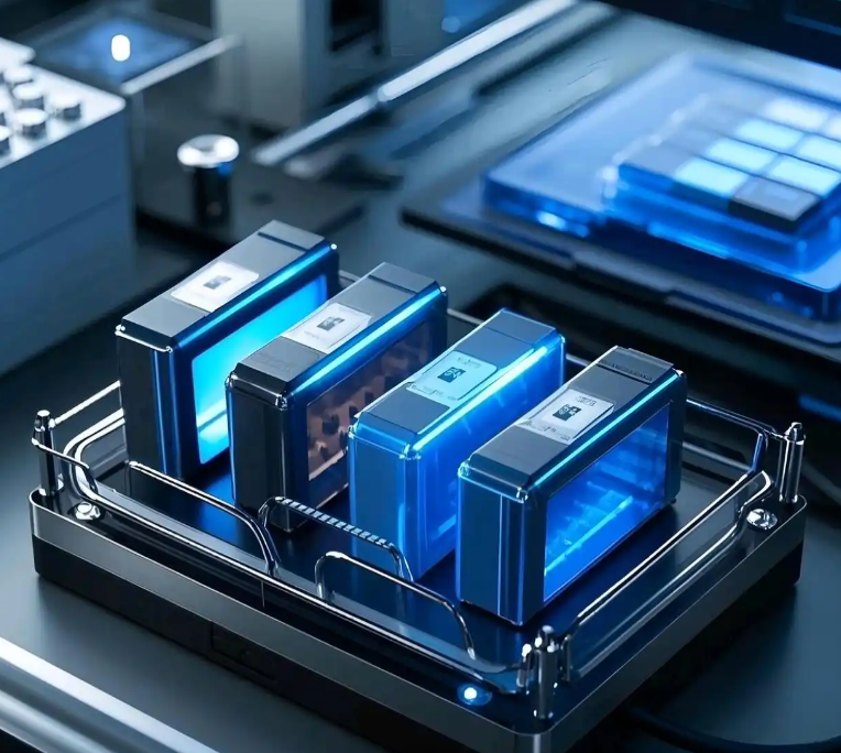
From my perspective, the functional separator is an underappreciated component. A conventional separator must be electrically insulating and ionically conductive through its pores. In a semi-solid-state battery, the separator also participates in safety and mechanical stabilization. A ceramic coating such as a garnet-type or NASICON-type oxide can raise the thermal shrinkage onset temperature and increase tensile strength. It can also act as a physical barrier against lithium dendrite penetration. The hybrid electrolyte and the functional separator together create a cooperative system rather than two independent layers.
| Component | Conventional lithium-ion battery | Semi-solid-state battery | All-solid-state battery |
|---|---|---|---|
| Positive electrode | LFP, NCM, LCO, NCA | LFP, NCM, high-voltage spinel, lithium-rich layered oxide | High-voltage cathode with solid electrolyte additive |
| Negative electrode | Graphite, silicon-carbon | Graphite, silicon-carbon, lithium metal | Lithium metal, silicon, alloy anode |
| Electrolyte | Liquid carbonate or ether electrolyte | Gel, in-situ cured polymer, composite solid electrolyte | Inorganic or solid polymer electrolyte |
| Separator | PP or PE porous membrane | Ceramic-coated PP or PE, composite separator | No separator or self-supporting solid electrolyte |
| Interface | Liquid-solid contact | Liquid-solid and solid-solid mixed contact | Solid-solid contact |
| Packaging | Aluminum or steel can, pouch | Pouch or prismatic, similar to conventional | High-pressure stack or specialized package |
4. Electrochemical Principles and Ion Transport
Macroscopically, the semi-solid-state battery operates like a rocking-chair battery. During charge, lithium ions leave the positive electrode, travel through the hybrid electrolyte and functional separator, and insert into the negative electrode. During discharge, the reverse process occurs. Electrons move through the external circuit. This description is simple, but the microscopic ion transport is more complex and is one of the reasons the semi-solid-state battery can retain good rate capability despite a low liquid content.
I view the ion transport in a semi-solid-state battery as a multi-path cooperative process. One fraction of lithium ions moves through residual liquid channels. Another fraction hops along polymer chain segments. A third fraction moves through the crystal lattice or grain boundaries of inorganic solid electrolyte particles. Ions also exchange between the solid and liquid phases at interfaces. This multi-path mechanism is the key to maintaining ionic conductivity. The total conductivity can be approximated as a sum over all charge carriers:
$$ \sigma = \sum_i n_i q_i \mu_i $$
Here, \( \sigma \) is ionic conductivity, \( n_i \) is carrier concentration, \( q_i \) is carrier charge, and \( \mu_i \) is carrier mobility. In a hybrid electrolyte, each path contributes a different weight, and the effective conductivity depends on the geometry, connectivity, and interfacial exchange rate. I often use the following general expression for ionic flux:
$$ J_i = -D_i \nabla c_i – \frac{\sigma_i t_i^+}{F} \nabla \phi $$
In this equation, \( J_i \) is the flux of species \( i \), \( D_i \) is the diffusion coefficient, \( c_i \) is concentration, \( \sigma_i \) is partial conductivity, \( t_i^+ \) is the transference number, \( F \) is Faraday’s constant, and \( \phi \) is electric potential. The first term describes diffusion, and the second term describes migration. In a well-designed semi-solid-state battery, the liquid phase provides fast diffusion pathways, while the solid phase provides mechanical support and safety.
Temperature dependence is also important. For many polymer and composite electrolytes, I use the Arrhenius equation or the Vogel-Tammann-Fulcher equation. The Arrhenius form is:
$$ \sigma T = A \exp\left(-\frac{E_a}{k_B T}\right) $$
where \( A \) is a pre-exponential factor, \( E_a \) is activation energy, \( k_B \) is Boltzmann’s constant, and \( T \) is absolute temperature. For amorphous polymer electrolytes above the glass transition temperature, the VTF equation is often more appropriate:
$$ \sigma = A T^{-1/2} \exp\left(-\frac{B}{T – T_0}\right) $$
Here, \( B \) is a pseudo-activation energy, and \( T_0 \) is the Vogel temperature. I mention these equations because they explain why some semi-solid-state batteries perform well at room temperature while others require elevated temperature. The presence of a liquid phase can lower the effective activation energy by providing a low-barrier pathway, but the solid phase can increase tortuosity and reduce the effective conductivity.
Interfacial resistance is another central issue. The overpotential at an interface can be written as:
$$ \eta_{\mathrm{int}} = j R_{\mathrm{int}} = j \frac{\rho_{\mathrm{int}}}{A} $$
where \( \eta_{\mathrm{int}} \) is interfacial overpotential, \( j \) is current density, \( R_{\mathrm{int}} \) is interfacial resistance, \( \rho_{\mathrm{int}} \) is specific interfacial resistivity, and \( A \) is area. In a semi-solid-state battery, the liquid phase helps wet the electrode surface, which reduces \( R_{\mathrm{int}} \) relative to an all-solid-state battery. However, if the liquid content is too low, the interface becomes starved, and \( R_{\mathrm{int}} \) rises sharply. This trade-off defines the practical window for semi-solid-state battery design.
| Transport pathway | Primary carrier | Typical conductivity contribution | Advantage | Limitation |
|---|---|---|---|---|
| Residual liquid channel | Solvated lithium ion | High, up to \(10^{-2}\) S/cm in bulk liquid | Fast ion transport, good wetting | Flammability risk if too much liquid |
| Polymer chain segment | Lithium ion coordinated to polymer | Moderate, \(10^{-7}\) to \(10^{-5}\) S/cm at room temperature | Flexibility, good contact | Low room-temperature conductivity |
| Inorganic solid electrolyte | Lithium ion in lattice or grain boundary | Moderate to high, \(10^{-4}\) S/cm for garnet or NASICON | High safety, dendrite resistance | Brittle, poor solid-solid contact |
| Solid-liquid interfacial exchange | Lithium ion exchange | Depends on interface area and chemistry | Couples fast liquid and safe solid paths | Can add resistance if unstable |
Dendrite suppression is another electrochemical benefit. In a conventional liquid battery, lithium metal tends to deposit unevenly, and dendrites can grow through the separator. A semi-solid-state battery with a ceramic-coated separator and a viscous or gel electrolyte increases the mechanical modulus and reduces the effective anion depletion near the lithium surface. A simplified Sand’s time expression for dendrite onset is:
$$ t_{\mathrm{Sand}} = \frac{\pi D}{4} \left( \frac{c_0 e}{J t_+} \right)^2 $$
In this expression, \( D \) is the ambipolar diffusion coefficient, \( c_0 \) is the initial salt concentration, \( e \) is the elementary charge, \( J \) is current density, and \( t_+ \) is the lithium-ion transference number. By increasing \( t_+ \) and reducing current density nonuniformity, the semi-solid-state battery can extend the time before dendrite nucleation. I have seen this effect in many cell designs, although it does not eliminate dendrites completely. For long cycle life with lithium metal, the interface chemistry and mechanical properties must still be carefully engineered.
5. Key Material Systems
I now turn to materials. The performance of a semi-solid-state battery depends strongly on the choice of electrolyte, electrode, and separator. I group the electrolyte options into three families: in-situ polymerized electrolytes, gel polymer electrolytes, and composite solid electrolytes. Each family has distinct advantages and limitations.
5.1 In-Situ Polymerized Electrolytes
In this approach, a liquid precursor containing monomers, initiators, lithium salts, and solvents is injected into the cell. After assembly, heat, ultraviolet light, or another trigger initiates polymerization. The result is a solid or gel polymer network that traps the liquid solvent. I like this method because it uses existing filling equipment and provides excellent initial wetting. The monomer conversion, curing temperature, and initiator concentration must be controlled precisely. If curing is incomplete, residual monomers can degrade electrochemical performance. If curing is too complete, the network becomes brittle and may crack during cycling. The ionic conductivity of the resulting electrolyte often follows the VTF behavior described earlier.
5.2 Gel Polymer Electrolytes
A gel polymer electrolyte is formed by absorbing a liquid electrolyte into a polymer matrix such as polyvinylidene fluoride-hexafluoropropylene, poly(methyl methacrylate), or polyacrylonitrile. The gel combines the high ionic conductivity of the liquid with the dimensional stability of the polymer. I have used gel electrolytes in pouch cells and found that they offer a good balance between safety and rate capability. The main challenge is mechanical strength. A gel can flow or creep under stack pressure, and it can lose liquid through evaporation if the packaging is not hermetic. The glass transition temperature and crystallinity of the polymer also affect low-temperature performance.
5.3 Composite Solid Electrolytes
A composite solid electrolyte disperses inorganic solid electrolyte particles such as garnet-type lithium lanthanum zirconium oxide or NASICON-type lithium aluminum titanium phosphate in a polymer matrix. The inorganic particles can improve ionic conductivity, mechanical modulus, and electrochemical stability. I often use percolation theory to describe the conductivity of such composites:
$$ \sigma = \sigma_0 (\phi – \phi_c)^t $$
Here, \( \phi \) is the volume fraction of inorganic filler, \( \phi_c \) is the percolation threshold, and \( t \) is a critical exponent. Below the threshold, the inorganic particles are isolated, and the polymer governs transport. Above the threshold, a continuous inorganic network can form and provide a fast pathway. In practice, high filler loading can make the composite brittle and difficult to process, so I usually target a compromise between conductivity and flexibility. The Maxwell-Garnett effective medium expression is also useful:
$$ \sigma_c = \sigma_p \frac{\sigma_i + 2\sigma_p + 2\phi(\sigma_i – \sigma_p)}{\sigma_i + 2\sigma_p – \phi(\sigma_i – \sigma_p)} $$
where \( \sigma_c \) is composite conductivity, \( \sigma_p \) is polymer conductivity, \( \sigma_i \) is inorganic conductivity, and \( \phi \) is filler volume fraction. This equation helps me estimate the benefit of adding a high-conductivity filler, although real composites often deviate because of interfacial resistance and particle agglomeration.
| Electrolyte family | Typical composition | Room-temperature conductivity | Mechanical behavior | Key advantage I value | Main challenge |
|---|---|---|---|---|---|
| In-situ polymerized | Monomer, initiator, lithium salt, solvent | \(10^{-4}\) to \(10^{-3}\) S/cm after curing | Moderate, network can be tuned | Excellent wetting and process compatibility | Curing control and residual monomer |
| Gel polymer | PVDF-HFP, PMMA, PAN with liquid electrolyte | \(10^{-3}\) S/cm or higher | Soft, viscoelastic | High conductivity and good flexibility | Mechanical creep and liquid retention |
| Composite solid | Polymer plus LLZO, LATP, or sulfide particles | \(10^{-5}\) to \(10^{-3}\) S/cm depending on filler | Stiffer, brittle at high filler loading | Improved safety and modulus | Dispersion, interfacial resistance, processability |
For the positive electrode, I prefer high-nickel layered oxides when high energy density is the priority. Lithium iron phosphate remains attractive for cost-sensitive and safety-critical applications. High-voltage spinels and lithium-rich layered oxides can increase cell voltage, but they require an electrolyte with a wide electrochemical stability window. The stability window can be estimated from molecular orbital energies:
$$ E_g = E_{\mathrm{LUMO}} – E_{\mathrm{HOMO}} $$
where \( E_{\mathrm{LUMO}} \) is the lowest unoccupied molecular orbital energy and \( E_{\mathrm{HOMO}} \) is the highest occupied molecular orbital energy. A wider \( E_g \) generally means a wider electrochemical stability window. In a semi-solid-state battery, the solid electrolyte component can raise the oxidation stability limit, which allows higher-voltage operation. I have seen this effect most clearly in composite electrolytes with oxide fillers.
For the negative electrode, graphite is still the workhorse. Silicon-carbon composites offer higher capacity, but they undergo large volume changes. The theoretical capacity of silicon is much higher than that of graphite, and the volume expansion can exceed 300%. A semi-solid-state electrolyte can accommodate some of this expansion because it is not a rigid ceramic. Lithium metal is the ultimate anode for energy density. Its theoretical capacity is:
$$ Q_{\mathrm{theo}} = \frac{n F}{M} $$
For lithium metal, \( Q_{\mathrm{theo}} \approx 3860 \) mAh/g. For graphite, \( Q_{\mathrm{theo}} \approx 372 \) mAh/g. This order-of-magnitude difference explains why so much effort is devoted to lithium metal anodes. However, lithium metal is highly reactive, and a semi-solid-state battery must control the solid electrolyte interphase and prevent continuous electrolyte consumption. I believe this is one of the most important research fronts for the solid state battery community.
| Electrode material | Theoretical capacity | Advantage | Challenge in semi-solid-state battery |
|---|---|---|---|
| Lithium iron phosphate | About 170 mAh/g | Excellent safety, long cycle life, low cost | Lower energy density |
| High-nickel NCM | About 200 to 220 mAh/g | High energy density | Surface reactivity, gas generation |
| High-voltage spinel | About 140 to 150 mAh/g | High operating voltage | Electrolyte oxidation, manganese dissolution |
| Graphite | 372 mAh/g | Mature, stable, low cost | Limited capacity |
| Silicon-carbon | Up to 1500 mAh/g or more | High capacity | Volume expansion, particle cracking |
| Lithium metal | 3860 mAh/g | Highest capacity, lowest potential | Dendrites, interface instability, safety |
6. Performance Benchmarking
When I compare battery technologies, I use several figures of merit: gravimetric energy density, volumetric energy density, ionic conductivity, safety, cost, cycle life, and manufacturing compatibility. The semi-solid-state battery does not win on every metric. Instead, it offers a balanced profile that I find more practical than either the conventional liquid battery or the all-solid-state battery for the near term.
The gravimetric energy density can be expressed as:
$$ E_{\mathrm{grav}} = \frac{Q V_{\mathrm{avg}}}{m_{\mathrm{cell}}} $$
where \( Q \) is cell capacity, \( V_{\mathrm{avg}} \) is average discharge voltage, and \( m_{\mathrm{cell}} \) is cell mass. A semi-solid-state battery can reach higher \( E_{\mathrm{grav}} \) than a conventional liquid battery because it can use a lithium metal anode or a high-silicon anode, and because the separator and packaging can be simplified. It does not reach the theoretical maximum of an all-solid-state battery because a small amount of liquid and a polymer network add mass. In my experience, a well-designed semi-solid-state battery can achieve 160 to 400 Wh/kg, depending on chemistry and cell design. An all-solid-state battery may exceed 500 Wh/kg in theory, but practical cells are still far from that number.
| Metric | Conventional liquid lithium-ion battery | Semi-solid-state battery | All-solid-state battery |
|---|---|---|---|
| Gravimetric energy density | 150 to 300 Wh/kg | 160 to 400 Wh/kg | Above 500 Wh/kg theoretical, lower in practice |
| Volumetric energy density | 300 to 700 Wh/L | 400 to 900 Wh/L | Potentially above 1000 Wh/L |
| Ionic conductivity | About \(10^{-2}\) S/cm | \(10^{-4}\) to \(10^{-3}\) S/cm | \(10^{-7}\) to \(10^{-2}\) S/cm, interface-limited |
| Safety | Lower, flammable liquid | Higher, reduced liquid | Highest in principle, no flammable liquid |
| Manufacturing compatibility | Fully mature | High, modified conventional lines | Low, new process and equipment |
| Cost | Low | Moderate | High today, uncertain future |
| Commercial status | Mature | Early commercialization | Pilot and small-scale |
Safety is a major reason I favor the semi-solid-state battery for near-term deployment. I quantify safety using onset temperature of self-heating, maximum temperature, gas generation, and heat release rate. A lower liquid content reduces the fuel available for combustion. A ceramic-coated separator increases the internal short-circuit resistance. A gel or composite electrolyte can also suppress lithium dendrite penetration. However, I must be honest: a semi-solid-state battery is not intrinsically safe under all abuse conditions. It can still undergo thermal runaway if the cell is overcharged, crushed, or exposed to an external fire. The improvement is incremental, not absolute. The all-solid-state battery has the potential to be safer, but only if the solid electrolyte is chemically stable against both electrodes and if the cell design avoids mechanical fracture.
| Safety test | Conventional liquid battery | Semi-solid-state battery | All-solid-state battery |
|---|---|---|---|
| Nail penetration | High risk of fire | Reduced risk, depending on liquid content | Low risk if mechanically stable |
| Overcharge | Gas generation, thermal runaway | Improved tolerance | Improved tolerance, but interface degradation |
| External heating | Early venting and fire | Delayed onset | Delayed onset, but solid electrolyte decomposition possible |
| Internal short circuit | Separator melting, rapid heat release | Ceramic coating raises short-circuit resistance | Solid electrolyte may resist dendrites but can crack |
7. Manufacturing and Scale-Up
I have visited and supported several pilot lines, and I can say that manufacturing compatibility is the strongest practical advantage of the semi-solid-state battery. The cell can be produced on equipment that is similar to conventional lithium-ion lines. The main changes are in electrolyte preparation, filling, curing, and formation. This means that a manufacturer does not need to abandon existing capital investment. The transition can be gradual.
The process sequence I typically see is as follows. First, the positive and negative electrodes are coated on current collectors using conventional slurry casting. Second, the functional separator is prepared by coating a ceramic layer onto a polyolefin membrane. Third, the electrodes and separator are stacked or wound into a cell. Fourth, the cell is dried and filled with a liquid precursor or gel precursor. Fifth, the cell is sealed and subjected to a curing step, such as heating or ultraviolet exposure. Sixth, the cell undergoes formation cycling, degassing, and final sealing. Each step has critical control parameters.
| Process step | Conventional lithium-ion battery | Semi-solid-state battery | Critical control parameter |
|---|---|---|---|
| Electrode coating | Slurry casting and drying | Similar, with possible solid electrolyte additive | Loading uniformity, adhesion |
| Separator preparation | Polyolefin membrane | Ceramic-coated or composite separator | Coating thickness, coverage, flexibility |
| Stacking or winding | Standard | Standard, with pressure control | Alignment, stack pressure |
| Electrolyte filling | Liquid electrolyte injection | Precursor injection, then curing | Wetting, precursor viscosity |
| Curing | Not required | Thermal or ultraviolet curing | Temperature, time, conversion |
| Formation | Standard formation cycling | Formation with pressure and temperature control | SEI stability, gas removal |
| Degassing and sealing | Standard | Important because curing can generate gas | Seal integrity, residual gas |
Cost is a major consideration. I use a simple cost model:
$$ C_{\mathrm{cell}} = C_{\mathrm{materials}} + C_{\mathrm{processing}} + C_{\mathrm{yield}} + C_{\mathrm{overhead}} $$
Here, \( C_{\mathrm{materials}} \) includes active materials, electrolyte, separator, current collectors, and packaging. \( C_{\mathrm{processing}} \) includes coating, stacking, filling, curing, and formation. \( C_{\mathrm{yield}} \) accounts for scrap and rework. \( C_{\mathrm{overhead}} \) includes facility and labor. In my analysis, the semi-solid-state battery has a moderate cost premium over conventional lithium-ion because the solid electrolyte materials, especially oxides, are more expensive, and the curing step adds time. However, the cost is much lower than an all-solid-state battery because the manufacturing line does not need a complete overhaul. As production volume increases, I expect the cost premium to shrink. The learning rate for battery manufacturing is often modeled as:
$$ C_N = C_1 N^{-\alpha} $$
where \( C_N \) is unit cost after \( N \) cumulative units, \( C_1 \) is first-unit cost, and \( \alpha \) is the learning exponent. For lithium-ion technology, \( \alpha \) has historically been around 0.1 to 0.2. I expect a similar or slightly lower learning rate for semi-solid-state batteries because some new materials and processes are involved.
| Cost driver | Conventional lithium-ion battery | Semi-solid-state battery | All-solid-state battery |
|---|---|---|---|
| Active material | Moderate | Moderate to high | High |
| Electrolyte | Low | Moderate | High |
| Separator | Low | Moderate, ceramic coating | Not applicable or high |
| Equipment | Mature, low depreciation | Partially compatible, moderate investment | New equipment, high investment |
| Processing time | Short | Moderate, curing step | Long, high-pressure sintering or stacking |
| Yield | High | Improving | Low today |
8. Characterization and Testing
I rely on a combination of electrochemical, structural, and thermal techniques to understand semi-solid-state battery behavior. Electrochemical impedance spectroscopy is my primary tool for separating bulk resistance, interfacial resistance, and charge-transfer resistance. A simplified impedance model can be written as:
$$ Z(\omega) = R_s + \frac{R_{ct}}{1 + (j\omega R_{ct} C_{dl})^\alpha} + \sigma_w (1-j)\omega^{-1/2} $$
Here, \( R_s \) is series resistance, \( R_{ct} \) is charge-transfer resistance, \( C_{dl} \) is double-layer capacitance, \( \alpha \) is a depression exponent, \( \sigma_w \) is the Warburg coefficient, and \( \omega \) is angular frequency. By fitting this model, I can track how the hybrid electrolyte and interfaces evolve during cycling. A growing \( R_{ct} \) often indicates interfacial degradation or electrolyte consumption. A growing \( R_s \) can indicate drying or loss of liquid connectivity.
Cyclic voltammetry helps me determine the electrochemical stability window. Galvanostatic cycling provides capacity, Coulombic efficiency, and rate capability. The C-rate is defined as:
$$ C_{\mathrm{rate}} = \frac{I}{Q} $$
where \( I \) is current and \( Q \) is nominal capacity. A 1C rate means the cell is fully charged or discharged in one hour. I also use state of charge and state of health definitions:
$$ \mathrm{SoC} = \frac{Q_{\mathrm{remaining}}}{Q_{\mathrm{max}}} $$
$$ \mathrm{SoH} = \frac{Q_{\mathrm{current}}}{Q_{\mathrm{initial}}} $$
These metrics are standard, but their interpretation in a semi-solid-state battery requires care because the available capacity can depend on temperature, pressure, and history. I have observed that some cells show a temporary capacity loss after high-rate cycling, which recovers after a low-rate rest. This suggests that concentration polarization and interfacial wetting, not permanent material degradation, are limiting performance.
| Technique | Information obtained | Why I use it |
|---|---|---|
| Electrochemical impedance spectroscopy | Bulk, interfacial, and charge-transfer resistance | To separate limiting mechanisms |
| Cyclic voltammetry | Redox potentials, stability window | To evaluate electrolyte compatibility |
| Galvanostatic cycling | Capacity, efficiency, cycle life | To benchmark practical performance |
| Scanning electron microscopy | Morphology, dendrite growth, particle cracking | To link microstructure to failure |
| X-ray photoelectron spectroscopy | Surface chemistry, SEI composition | To understand interface reactions |
| Nuclear magnetic resonance | Ion dynamics, polymer chain mobility | To study transport mechanisms |
| Differential scanning calorimetry | Glass transition, melting, crystallinity | To optimize polymer and gel properties |
| Accelerating rate calorimetry | Thermal runaway onset and heat release | To quantify safety improvements |
9. Degradation and Failure Modes
No technology is perfect, and I have learned to respect the degradation modes of the semi-solid-state battery. The most common failure modes are interfacial resistance growth, lithium inventory loss, electrolyte consumption, gas generation, and mechanical fatigue. These modes are often coupled. For example, gas generation can increase internal pressure, which can cause delamination at the solid-liquid interface, which in turn increases resistance and promotes further gas generation.
Interfacial resistance growth is usually caused by continuous side reactions between the electrolyte and the electrodes. In a semi-solid-state battery, the liquid phase can wet the surface but also reacts with lithium metal. The solid electrolyte interphase can grow thicker over time, consuming lithium and electrolyte. I use the following simplified resistance growth model:
$$ R_{\mathrm{int}}(t) = R_{\mathrm{int},0} + k t^n $$
where \( R_{\mathrm{int},0} \) is initial interfacial resistance, \( k \) is a rate constant, \( t \) is time, and \( n \) is an exponent. A value of \( n \approx 0.5 \) suggests diffusion-limited growth, while \( n \approx 1 \) suggests reaction-limited growth. By tracking \( R_{\mathrm{int}} \) over time, I can infer which mechanism dominates.
Lithium inventory loss is especially important for cells with lithium metal anodes. During cycling, lithium is consumed by side reactions, and the cell capacity fades. The loss can be quantified as:
$$ Q_{\mathrm{loss}} = Q_0 – Q_{\mathrm{remaining}} $$
where \( Q_0 \) is the initial capacity. To extend cycle life, I focus on three strategies: interface protection, electrolyte formulation, and lithium alloying. A protective layer can reduce direct contact between lithium and the liquid phase. A salt additive can form a more stable SEI. A lithium alloy can reduce reactivity and control deposition morphology.
Mechanical fatigue is another challenge. During charge and discharge, electrode particles expand and contract. The hybrid electrolyte must accommodate this strain without losing contact. If the electrolyte is too rigid, it can crack. If it is too soft, it can creep and lose dimensional stability. I often use a composite design with a flexible polymer matrix and rigid inorganic fillers to balance these properties. The effective modulus of a composite can be estimated with the rule of mixtures:
$$ E_c = \phi E_i + (1-\phi) E_p $$
where \( E_c \) is composite modulus, \( E_i \) is inorganic modulus, \( E_p \) is polymer modulus, and \( \phi \) is filler volume fraction. A higher modulus helps suppress dendrites, but it also increases the risk of brittle fracture. This is a classic trade-off in solid state battery design.
| Degradation mode | Root cause | Symptom | Mitigation I consider |
|---|---|---|---|
| Interfacial resistance growth | Side reactions, SEI thickening | Impedance rise, voltage polarization | Surface coating, salt additives |
| Lithium inventory loss | Irreversible lithium consumption | Capacity fade, low Coulombic efficiency | Protected lithium, alloy anode, optimized SEI |
| Electrolyte consumption | Continuous reaction with electrodes | Dry-out, resistance increase | Stable electrolyte, reduced liquid activity |
| Gas generation | Solvent reduction, cathode oxidation | Swelling, delamination, safety risk | Gas-absorbing additives, degassing process |
| Mechanical fatigue | Electrode volume change, stack pressure | Cracking, contact loss | Composite electrolyte, elastic binder, pressure control |
10. Industrialization Status and Applications
I am encouraged by the pace of industrialization. The semi-solid-state battery has moved from concept validation to commercial deployment in a relatively short time. Several automotive manufacturers have announced vehicles with semi-solid-state battery packs, and some have already delivered limited volumes. The first applications have been in premium electric vehicles, where long driving range and improved safety justify a higher cost. I expect the next wave to include electric vertical takeoff and landing aircraft, grid-scale energy storage, and high-end consumer electronics.
In electric vehicles, the main value proposition is range and safety. A semi-solid-state battery with a lithium metal or high-silicon anode can push pack-level energy density beyond what conventional lithium-ion batteries can achieve. This can translate into a driving range of more than 1000 km on a single charge for some platforms. The reduced liquid content also improves tolerance to abuse. I have seen crash tests and nail penetration tests where semi-solid-state cells vent less violently than conventional cells. This does not mean they are fireproof, but the safety margin is wider.
In electric aviation, the requirements are even more demanding. Energy density must be high, and safety must be exceptional. A solid state battery is widely considered the long-term solution, but the semi-solid-state battery may be the first to meet certification requirements because it uses a lower-risk liquid content and can be manufactured with known processes. I believe electric aviation will be an early adopter of semi-solid-state technology, especially for short-range and urban air mobility.
In stationary energy storage, cycle life and cost are more important than gravimetric energy density. A semi-solid-state battery with lithium iron phosphate cathode and graphite or silicon-carbon anode can offer a good combination of safety, cycle life, and cost. The reduced flammability is a major advantage for large-scale installations. I expect grid operators and utilities to adopt semi-solid-state batteries as they become cost-competitive.
| Application | Primary requirement | Why semi-solid-state battery fits | Commercial timing I anticipate |
|---|---|---|---|
| Premium electric vehicles | High energy density, safety | Long range, improved abuse tolerance, existing supply chain | Early commercialization already underway |
| Electric aviation | Very high energy density, safety | Transition path to solid state battery, better safety than liquid | Pilot and certification phase |
| Grid energy storage | Low cost, long cycle life, safety | Reduced flammability, scalable manufacturing | Near-term growth |
| Consumer electronics | High volumetric energy density, safety | Thin cells, flexible form factors | Selective adoption |
| Medical devices | Reliability, safety | Hermetic packaging compatibility | Niche adoption |
11. Future Research Directions and Challenges
I see four major research directions for the semi-solid-state battery. The first is interface engineering. The solid-liquid and solid-solid interfaces must be stabilized. Surface coatings on electrodes, optimized electrolyte additives, and in-situ formed interphases are promising. I believe the most impactful work will be at the interface between lithium metal and the hybrid electrolyte, because that is where safety and cycle life are most strongly coupled.
The second direction is new materials. Higher ionic conductivity, wider electrochemical stability, and lower cost are the targets. Oxide electrolytes such as garnet and NASICON are stable but brittle. Sulfide electrolytes are soft and conductive but sensitive to moisture. Halide electrolytes are emerging as a promising compromise. For the solid state battery to reach its full potential, new solid electrolytes with better processability and lower cost are needed. In the semi-solid-state battery, these materials can be used as fillers or coatings, which reduces the performance burden compared with an all-solid-state battery.
The third direction is lithium metal stability. Although the semi-solid-state battery can suppress dendrites better than a liquid battery, it does not eliminate them. I want to see long cycle life with high Coulombic efficiency. This requires a combination of electrolyte formulation, interface protection, and stack pressure control. The transference number is a key parameter. A higher lithium-ion transference number reduces concentration polarization and delays dendrite onset. I use the Bruce-Vincent method to estimate it:
$$ t_+ = \frac{I_{ss}(\Delta V – I_0 R_0)}{I_0(\Delta V – I_{ss} R_{ss})} $$
where \( I_0 \) is initial current, \( I_{ss} \) is steady-state current, \( \Delta V \) is applied potential, and \( R_0 \) and \( R_{ss} \) are initial and steady-state resistances. Improving \( t_+ \) is one of the most practical ways to improve lithium metal cycling.
The fourth direction is cost reduction. The semi-solid-state battery must compete with conventional lithium-ion batteries on cost. The solid electrolyte materials, ceramic coatings, and curing processes add cost. I believe that scale, material innovation, and process optimization will reduce the premium. The learning curve model I presented earlier suggests that cumulative production is the most powerful lever. Governments and industry can accelerate cost reduction by supporting pilot lines and early deployment.
| Research direction | Specific target | Technical approach | Expected impact on solid state battery transition |
|---|---|---|---|
| Interface engineering | Reduce interfacial resistance, stabilize SEI | Coatings, additives, in-situ curing | Directly transferable to all-solid-state battery |
| New materials | Higher conductivity, wider stability, lower cost | Halides, sulfides, composite oxides | Provides material library for solid state battery |
| Lithium metal stability | High Coulombic efficiency, dendrite suppression | Electrolyte formulation, pressure control, alloying | Enables high-energy solid state battery |
| Cost reduction | Lower $/kWh | Scale, process intensification, material substitution | Accelerates market adoption of solid state battery |
12. My Perspective on the Roadmap
I do not think the industry will jump directly from liquid lithium-ion to all-solid-state. The transition will be staged. In the near term, semi-solid-state batteries will enter premium electric vehicles and specialized applications. In the mid term, quasi-solid-state batteries with lower liquid content will be developed, and manufacturing processes will mature. In the long term, all-solid-state batteries will become commercially viable for mass-market applications. The semi-solid-state battery is the first stage of this roadmap, and I believe it will remain relevant for at least the next decade.
| Time horizon | Technology focus | Liquid content | Key milestone | My expectation |
|---|---|---|---|---|
| Near term, 2025 to 2030 | Semi-solid-state battery with gel or composite electrolyte | 5% to 15% | Large-scale vehicle deployment | Steady growth, cost reduction |
| Mid term, 2030 to 2035 | Quasi-solid-state battery with trace liquid | 1% to 5% | Higher energy density, improved safety | Transition to solid state battery platforms |
| Long term, beyond 2035 | All-solid-state battery | Less than 1% | Mass-market solid state battery | Ultimate solution for high-energy, high-safety storage |
One question I often ask myself is whether the semi-solid-state battery is a temporary solution or a permanent one. My answer is that it is both. For some applications, such as grid storage and commercial vehicles, the semi-solid-state battery may be sufficient for many years. For other applications, such as long-range aviation and premium electric vehicles, it is a stepping stone to the all-solid-state battery. In either case, the knowledge gained from semi-solid-state battery research and manufacturing is invaluable. It teaches us how to control interfaces, how to scale solid electrolyte production, and how to design cells with reduced liquid content. These lessons will directly benefit the solid state battery.
13. Conclusion
I have argued that the semi-solid-state battery is a practical, scalable, and strategically important technology. It reduces the safety risks of conventional liquid lithium-ion batteries while avoiding the most difficult manufacturing and interfacial problems of the all-solid-state battery. It offers a realistic path to higher energy density, and it can be produced on modified existing lines. I have presented definitions, architecture, electrochemical mechanisms, material systems, performance benchmarks, manufacturing considerations, characterization methods, degradation modes, and industrialization trends. I have also highlighted the challenges that remain: interfacial resistance, lithium metal stability, cost, and scale-up.
In my view, the solid state battery is the future, but the semi-solid-state battery is the bridge that will carry the industry there. The next five to ten years will be decisive. I expect to see continued improvements in electrolyte conductivity, interface stability, and cell design. I expect costs to decline as production volume increases. I expect safety standards to become more stringent, which will favor batteries with lower liquid content. I also expect the semi-solid-state battery to be the first solid state battery family to achieve widespread commercial success. The solid state battery era will not arrive all at once. It will arrive step by step, and the semi-solid-state battery is the first step. I am confident that this technology will play a central role in the transition to a safer, more energy-dense, and more sustainable energy storage future.