
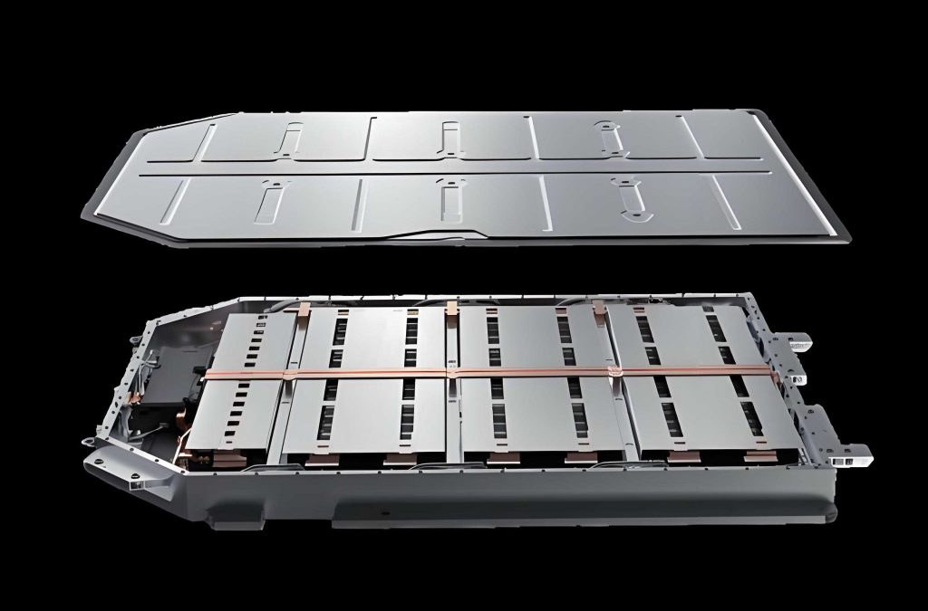
In my research, I focus on the crash safety of the electric vehicle battery pack because the bottom of an electric vehicle battery pack is directly exposed to road debris, curbs, stones, metal rods, and other foreign objects. When an electric vehicle battery pack suffers a bottom impact, the protective shell, the module frame, and the battery cells can deform. If the deformation exceeds a safe limit, electrolyte leakage, internal short circuits, fire, and even explosion may occur. Therefore, I propose a DNA-inspired double-helix bionic honeycomb structure for electric vehicle battery pack bottom impact protection. The design is motivated by the mechanical stability of the DNA double helix, which combines global flexibility with local reinforcement. I combine finite element simulation, machine-learning-assisted surrogate modeling, and multi-objective metaheuristic optimization to obtain a protective structure that absorbs more energy, transmits a lower peak force, and limits the compression of the electric vehicle battery pack.
The core idea of my work is to place a bionic reinforcing-rib network inside a conventional hexagonal honeycomb so that the electric vehicle battery pack receives multi-directional support under puncture, bottoming, and oblique impact. The proposed structure is not a simple geometric decoration. It changes the deformation mode from unstable local buckling to progressive plastic crushing. This change is central to protecting the electric vehicle battery pack under extreme road-impact conditions. I evaluate the structure with energy absorption, specific energy absorption, peak crushing force, mean crushing force, and maximum axial compression of the battery cells. I also assess the robustness of the optimized electric vehicle battery pack protector under different impact angles, impact velocities, and impactor shapes.
In the road foreign-object scenario, I assume that the vehicle has a ground clearance \(H\) and the road impactor has a characteristic length \(L\). If the impactor is low enough, the vehicle passes safely. If the impactor is high enough, it strikes the bottom of the electric vehicle battery pack. A simplified geometric condition can be written as:
$$\sin\alpha < \frac{H}{L} \quad \text{safe passage}$$
$$\sin\alpha \ge \frac{H}{L} \quad \text{impact occurs}$$
I selected the puncture condition because it is one of the most damaging bottom-impact modes for an electric vehicle battery pack. A triangular pyramid was used to represent an irregular road stone. This shape creates a sharp tip and a well-defined contact area, and it is closer to real road debris than a perfect sphere or cone. The impactor mass was 568 g, the bottom side length was 130 mm, the cone angle was 90°, and the vertical impact velocity was 30 m/s. The kinetic energy is:
$$E_k = \frac{1}{2} m v^2$$
$$E_k = \frac{1}{2}(0.568)(30)^2 = 255.6 \text{ J}$$
For comparison, a 150 J mandatory bottom-impact threshold with a 568 g impactor corresponds to:
$$v = \sqrt{\frac{2E_k}{m}} = \sqrt{\frac{2(150)}{0.568}} \approx 22.98 \text{ m/s}$$
Thus, my chosen 30 m/s condition represents a more severe scenario for the electric vehicle battery pack, with about 70% more impact energy than the basic mandatory threshold. This is important because the protective structure should not be designed only for the minimum legal requirement; it should also provide a safety margin for high-speed road debris impact.
| Road foreign-object parameter | Value |
|---|---|
| Impactor shape | Triangular pyramid |
| Mass | 568 g |
| Bottom side length | 130 mm |
| Cone angle | 90° |
| Impact velocity | 30 m/s |
| Impact energy | 255.6 J |
| Impact direction | Vertical puncture |
| Equivalent density | 3000 kg/m³ |
| Equivalent Young’s modulus | 210 GPa |
| Equivalent Poisson’s ratio | 0.3 |
For the finite element model, I used an explicit dynamic solver. The honeycomb material was AA3003 H18 aluminum alloy. The shell elements were four-node reduced-integration elements with five integration points through the thickness. This choice captures bending, membrane stretching, and local folding of thin cell walls. General contact was used between the impactor and the protective structure, and self-contact was used between cell walls. The tangential friction coefficient was 0.2, and the normal contact was hard contact with separation allowed. The material properties are summarized below.
| Material property | Value |
|---|---|
| Material | AA3003 H18 aluminum alloy |
| Density | 2.7 g/cm³ |
| Elastic modulus | 69 GPa |
| Poisson’s ratio | 0.33 |
| Initial yield strength | 115.8 MPa |
| Ultimate strength | 154.5 MPa |
| Element type | S4R shell |
| Integration points | 5 through thickness |
| Friction coefficient | 0.2 |
I used a two-stage validation strategy to ensure that the numerical model can be trusted for the electric vehicle battery pack protection study. The first stage was quasi-static out-of-plane compression of a conventional hexagonal honeycomb. The second stage was puncture impact of a honeycomb sandwich panel, which is closer to the actual loading mode of an electric vehicle battery pack under road-debris impact. The validation errors for peak crushing force and energy absorption were both below 5%, and the force-displacement curves showed good agreement. This confirms that the element formulation, material constitutive model, contact definition, and progressive crushing behavior are reliable.
| Loading scenario | Peak crushing force error | Energy absorption error |
|---|---|---|
| Quasi-static compression | 3.36% | 3.97% |
| Puncture impact | 3.21% | 3.85% |
For the coupled road foreign-object–protective structure–battery module model, I used a scaled electric vehicle battery pack model to balance accuracy and computational cost. The upper and lower pack shells were made of 7075-T6 aluminum alloy and were meshed with four-node reduced-integration shell elements. The 18650 cylindrical cell was represented with a homogenized jellyroll model. The internal separator, electrolyte, electrode, and current collector were homogenized into an equivalent plastic-like material. The cell casing was represented by a thin soft steel shell. The module top and bottom plates were also included to maintain structural integrity during impact. The main components are listed below.
| Component | Material or model | Key parameters |
|---|---|---|
| Upper pack shell | 7075-T6 aluminum alloy | Thin shell structure |
| Lower pack shell | 7075-T6 aluminum alloy | Thin shell structure |
| Battery cell | 18650 cylindrical cell | Diameter 18 mm, height 65 mm |
| Jellyroll | Homogenized equivalent material | \(E = 2.2\) GPa, \(\nu = 0.3\), \(\sigma_y = 35\) MPa |
| Cell casing | Soft steel | Thickness 0.3 mm, \(E = 210\) GPa, \(\nu = 0.27\) |
| Module top and bottom | 7075-T6 aluminum alloy | Protective plates |
| Protective core | DNA-inspired bionic honeycomb | Aluminum alloy AA3003 H18 |
| Impactor | Discrete rigid body | Triangular pyramid, 568 g |
To compare crashworthiness, I used several standard indicators. The energy absorption is the integral of the force-displacement curve up to an effective compression displacement \(\delta\):
$$EA = \int_{0}^{\delta} F(x)\,dx$$
The specific energy absorption is the energy absorption per unit mass:
$$SEA = \frac{EA}{M} = \frac{\int_{0}^{\delta} F(x)\,dx}{M}$$
The mean crushing force is the average force over the effective compression displacement:
$$MCF = \frac{EA}{\delta}$$
The peak crushing force is the maximum force during compression:
$$PCF = \max F(x)$$
For an electric vehicle battery pack, a high \(SEA\) and a high \(MCF\) are desirable, while a low \(PCF\) is also necessary because the battery module and passenger compartment should not receive an excessive instantaneous load. I therefore treat the design as a multi-objective problem rather than a single-indicator problem.
Inspired by the DNA double helix, I added bionic reinforcing ribs to a conventional hexagonal honeycomb. I considered several derivative layouts by changing the arrangement and number of longitudinal and transverse ribs. To ensure a fair comparison, all structures used the same aluminum alloy, the same overall dimensions, the same basic hexagonal cell parameters, and a uniform wall or rib thickness of 0.4 mm. I then normalized the mass effect through \(SEA\). The derived configurations and their energy-absorption characteristics are shown below.
| Configuration | EA / J | SEA / (J·g⁻¹) | PCF / kN | MCF / kN |
|---|---|---|---|---|
| HC | 86.05 | 0.6236 | 34.03 | 9.86 |
| DNA-L1 | 99.42 | 0.6373 | 34.30 | 11.52 |
| DNA-H1 | 102.2 | 0.6421 | 36.52 | 12.21 |
| DNA-L2 | 103.9 | 0.6005 | 35.01 | 13.32 |
| DNA-L2H1 | 122.8 | 0.6331 | 38.07 | 14.50 |
| DNA-H1L1 | 116.1 | 0.6602 | 37.39 | 13.73 |
| DNA-L3 | 121.8 | 0.6376 | 34.34 | 14.57 |
| DNA-L3H1 | 139.1 | 0.6592 | 35.91 | 16.54 |
| DNA-H3L1 | 140.8 | 0.6612 | 36.97 | 17.63 |
| DNA-L3H2 | 153.2 | 0.6993 | 39.13 | 19.24 |
| DNA-H3L3 | 158.1 | 0.6557 | 36.89 | 18.90 |
The results show that increasing the number of ribs does not always improve the specific energy absorption. The DNA-L3H2 configuration has the highest \(SEA\) at 0.6993 J/g, which is 12.14% higher than the conventional honeycomb. It also has the highest \(MCF\) at 19.24 kN, which is 95.13% higher than the conventional honeycomb. Its \(PCF\) is 39.13 kN, only 14.99% higher than the conventional honeycomb. The total \(EA\) is 153.2 J, 78.04% higher than the conventional honeycomb and only 3.1% lower than the over-dense DNA-H3L3 configuration. Therefore, DNA-L3H2 provides the best balance for the electric vehicle battery pack bottom protector. The mechanism is that the staggered longitudinal and transverse ribs create a continuous spatial support system. The ribs transfer load between adjacent cell walls and delay local buckling. In contrast, an over-dense rib layout causes excessive local stiffness, shear buckling, and material redundancy. The conventional honeycomb buckles locally and uses less material in plastic deformation.
After selecting DNA-L3H2, I performed parametric design of experiments. The geometric variables were the cell angle \(\theta\), cell height \(H\), cell wall thickness \(t\), and plate thickness \(h\). The ranges were chosen according to manufacturing limits, installation space, lightweight requirements, and load-transfer needs. I used a full factorial design with 450 sample points, and each sample was simulated to obtain \(SEA\), \(PCF\), and battery axial compression displacement. Eighty percent of the data were used for training, and twenty percent were used for validation.
| Parameter | Range | Reason for range |
|---|---|---|
| Cell angle \(\theta\) | 30°–60° | Avoid stress concentration and excessive stiffness loss |
| Cell height \(H\) | 6.0–14.0 mm | Provide deformation stroke and maintain ground clearance |
| Cell wall thickness \(t\) | 0.4–1.4 mm | Satisfy manufacturing and lightweight constraints |
| Plate thickness \(h\) | 1.0–3.0 mm | Balance stiffness, load transfer, and peak force |
Manual modeling of 450 finite element models would be inefficient and prone to inconsistency. I therefore used the Python scripting interface of the finite element code for secondary development. The parametric modeling workflow included geometry generation, material assignment, boundary condition definition, contact setup, job submission, and result extraction. The scripts ensured that all 450 cases had identical modeling assumptions. This produced a high-quality dataset for machine-learning-assisted optimization of the electric vehicle battery pack protector.
For the surrogate model, I used support vector regression optimized by a metaheuristic algorithm. The metaheuristic algorithm searches for the penalty coefficient \(C\), the kernel parameter \(\gamma\), and the insensitive loss parameter \(\epsilon\). The objective is to minimize validation error. The optimized model is referred to as CPOSVR. The comparison between the unoptimized SVR and CPOSVR is shown below.
| Hyperparameter | SVR | CPOSVR | Search range |
|---|---|---|---|
| Penalty coefficient \(C\) | 1.0 | 8.73 | [0.1, 100] |
| Kernel parameter \(\gamma\) | 0.25 | 0.18 | [0.01, 10] |
| Insensitive loss \(\epsilon\) | 0.1 | 0.05 | [0.01, 0.5] |
| Test mean absolute error | 0.078 | 0.052 | — |
The prediction accuracy was evaluated with root mean square error and the coefficient of determination. The root mean square error is:
$$RMSE = \sqrt{\frac{1}{n}\sum_{i=1}^{n}(Y_i-\hat{Y}_i)^2}$$
The coefficient of determination is:
$$R^2 = 1 – \frac{\sum_{i=1}^{N}(y_i-\hat{y}_i)^2}{\sum_{i=1}^{N}(y_i-\bar{y})^2}$$
For an engineering surrogate model, \(R^2 \ge 0.9\) and \(RMSE \le 0.1\) are generally considered acceptable. The trained CPOSVR model achieved \(R^2\) close to 1 and \(RMSE\) below 0.1 for \(SEA\), \(PCF\), and battery axial compression displacement. The prediction errors were within 6% for \(SEA\), within 9% for \(PCF\), and within 6% for axial compression. This level of accuracy is sufficient for subsequent multi-objective optimization of the electric vehicle battery pack protective structure.
| Output | Maximum validation error | Accuracy assessment |
|---|---|---|
| Specific energy absorption \(SEA\) | Within 6% | Acceptable |
| Peak crushing force \(PCF\) | Within 9% | Acceptable |
| Battery axial compression \(d\) | Within 6% | Acceptable |
For multi-objective optimization, I used a coati-inspired metaheuristic algorithm, referred to as MOCOA. I selected it because it has strong evolutionary power, fast convergence, high convergence accuracy, and good Pareto diversity. It can generate a well-distributed Pareto set for the electric vehicle battery pack protection problem. The optimization problem is defined as follows:
$$\min_X \left\{ -SEA(X),\; PCF(X),\; d_{\text{battery}}(X) \right\}$$
where the design variables are:
$$X = [\theta, H, t, h]$$
subject to:
$$30^\circ \le \theta \le 60^\circ$$
$$6.0\,\text{mm} \le H \le 14.0\,\text{mm}$$
$$0.4\,\text{mm} \le t \le 1.4\,\text{mm}$$
$$1.0\,\text{mm} \le h \le 3.0\,\text{mm}$$
$$d_{\text{battery}}(X) < 4.0\,\text{mm}$$
The last constraint is based on the observation that axial compression beyond about 4 mm can cause internal short circuits in commercial 18650 cells. For most cells, safety can be maintained when axial compression is less than about 2 mm. In my simulations, all cells remained below 1 mm, which is far below the 4 mm risk threshold. This means the proposed electric vehicle battery pack protector can prevent mechanical failure under the studied impact conditions.
The MOCOA generated a Pareto front with 66 non-dominated solutions. The utopia point represents an unachievable ideal where all objectives are simultaneously optimal. The knee point represents the best compromise between conflicting objectives. I used a constraint-screened weighted distance method to select the final design. Because \(PCF\) directly controls the impact load transmitted to the electric vehicle battery pack and the passenger compartment, I assigned it a weight of 0.6. Because \(SEA\) affects vehicle range and lightweight design, I assigned it a weight of 0.4. The weighted distance is:
$$d_i = \sqrt{\lambda_{PCF}\left(\frac{PCF_i-PCF_{\min}}{PCF_{\max}-PCF_{\min}}\right)^2 + \lambda_{SEA}\left(\frac{SEA_{\max}-SEA_i}{SEA_{\max}-SEA_{\min}}\right)^2}$$
where:
$$\lambda_{PCF}=0.6,\quad \lambda_{SEA}=0.4$$
$$PCF_{\min}=22.6\,\text{kN},\quad PCF_{\max}=32.53\,\text{kN}$$
$$SEA_{\min}=0.55\,\text{J/g},\quad SEA_{\max}=0.82\,\text{J/g}$$
The selected knee point has \(SEA = 0.629\) J/g, \(PCF = 23.61\) kN, and battery axial compression \(d = 0.213\) mm. Its weighted distance is 0.4543, which is lower than the high-\(SEA\) points selected by an equal-weight method. At this point, \(PCF\) is reduced by 13.7% compared with the equal-weight optimum, while \(SEA\) decreases by only 10.6%. This means the safety benefit outweighs the small loss in lightweight energy absorption. The reverse-designed geometric parameters are listed below.
| \(SEA\) / (J·g⁻¹) | \(PCF\) / kN | \(d\) / mm | \(h\) / mm | \(H\) / mm | \(t\) / mm | \(\theta\) / ° |
|---|---|---|---|---|---|---|
| 0.629 | 23.61 | 0.213 | 2.20 | 14 | 0.4 | 43.91 |
I then built a finite element model with the optimized geometric parameters and compared the simulation results with the optimization results. The errors were small, which confirms the reliability of the machine-learning-assisted multi-objective design framework for the electric vehicle battery pack protector.
| Indicator | Optimization result | Finite element simulation | Error |
|---|---|---|---|
| \(SEA\) / (J·g⁻¹) | 0.629 | 0.653 | 3.68% |
| \(PCF\) / kN | 23.61 | 25.17 | 6.61% |
| \(d\) / mm | 0.213 | 0.229 | 7.51% |
The protective effect of the electric vehicle battery pack structure can be evaluated by the reduction in maximum axial compression of the battery:
$$PE = \frac{d_0 – d_1}{d_0} \times 100\%$$
where \(d_0\) is the initial battery axial compression and \(d_1\) is the axial compression after adopting the optimized protective structure. In my study, the initial DNA-L3H2 structure gave 0.719 mm, and the optimized DNA-L3H2 structure gave 0.229 mm. Therefore:
$$PE = \frac{0.719 – 0.229}{0.719} \times 100\% = 68.15\%$$
Compared with the initial design, the optimized electric vehicle battery pack protector achieved a 44.3% increase in energy absorption, a 35.68% reduction in peak crushing force, and a 68.1% decrease in maximum battery compression displacement. I also compared the optimized structure with several typical protective structures reported in prior studies. The optimized DNA-inspired honeycomb provided the best overall protective effect in terms of battery axial compression and protection evaluation. The comparison is summarized below.
| Structural type | Axial compression displacement / mm | \(PE\) |
|---|---|---|
| Traditional homogeneous panel | 3.17 | — |
| Circular core structure | 1.03 | 67.50% |
| Sandwich panel with bionic reinforcement | 1.07 | 66.25% |
| Laminated bionic scales | 1.20 | 62.15% |
| Optimized DNA-inspired honeycomb | 0.229 | 68.15% |
The optimized electric vehicle battery pack protector also performed well under different impact angles. I kept the impactor mass, speed, and geometry unchanged and varied the impact angle from vertical to 15°, 30°, and 45°. The energy absorption decreased as the angle increased because the normal component of the impact energy decreased. The peak crushing force increased with angle because tangential slip and local intrusion enlarged the contact area. However, the battery axial compression remained far below the safety threshold, and no buckling instability occurred. This confirms that the optimized electric vehicle battery pack structure has wide-angle impact adaptability.
| Impact angle | EA / J | PCF / kN | Battery compression / mm |
|---|---|---|---|
| 0° | 180.60 | 25.17 | 0.229 |
| 15° | 175.21 | 26.75 | 0.133 |
| 30° | 167.64 | 32.81 | 0.174 |
| 45° | 148.93 | 42.73 | 0.215 |
I also evaluated the optimized electric vehicle battery pack protector under different impact velocities. Four speeds were considered: 20 m/s, 30 m/s, 40 m/s, and 50 m/s. The energy absorption increased significantly with speed. The peak crushing force increased nonlinearly because momentum transfer, inertia, and strain-rate effects became stronger at high speed. The battery axial compression increased approximately linearly with speed, but even at 50 m/s it remained below 1 mm, which is still below the 2 mm safety threshold for most commercial cells. This shows that the optimized DNA-inspired honeycomb provides a sufficient safety margin for the electric vehicle battery pack under high-speed road impact.
| Impact velocity | EA / J | PCF / kN | Battery compression / mm |
|---|---|---|---|
| 20 m/s | 101.51 | 18.42 | 0.116 |
| 30 m/s | 180.60 | 25.17 | 0.229 |
| 40 m/s | 299.39 | 41.95 | 0.478 |
| 50 m/s | 411.67 | 68.25 | 0.992 |
Different shapes of road foreign objects produce different contact modes and stress concentrations. I compared a triangular pyramid, a sphere, a tetrahedron, and a cylinder. All impactors had the same mass of 568 g, the same impact speed of 30 m/s, and the same vertical impact angle. The triangular pyramid produced the highest energy absorption and the lowest peak crushing force because its contact area expanded gradually and its tip drove progressive plastic crushing of the honeycomb cells. The cylindrical impactor produced the highest peak force because line contact caused shear yielding of cell walls. The spherical impactor caused face-contact bending and ring-shaped deformation, which was less efficient for energy absorption. The tetrahedral impactor had multiple contact points and produced an elliptical damage zone.
| Impactor shape | EA / J | PCF / kN | Battery compression / mm | \(PE\) |
|---|---|---|---|---|
| Triangular pyramid | 180.60 | 25.17 | 0.229 | 68.15% |
| Sphere | 176.16 | 39.22 | 0.255 | 64.53% |
| Tetrahedron | 177.88 | 47.98 | 0.273 | 62.03% |
| Cylinder | 171.75 | 55.78 | 0.305 | 57.58% |
In summary, I designed a DNA-inspired double-helix bionic honeycomb for electric vehicle battery pack bottom impact protection. The structure uses staggered reinforcing ribs to improve multi-directional support, delay local buckling, and promote progressive plastic deformation. I built a coupled road foreign-object–protective structure–battery module model, validated the finite element method against benchmark compression and puncture impact data, and generated a 450-sample dataset through parametric modeling. I then trained a CPOSVR surrogate model and used MOCOA to solve the multi-objective optimization problem. The optimized electric vehicle battery pack protector achieved higher energy absorption, lower peak crushing force, and much lower battery compression than the initial design. It also performed well under different impact angles, impact velocities, and impactor shapes. These results provide a new technical path for improving the bottom-impact safety of the electric vehicle battery pack.
I also note several limitations. The current conclusions are based on a scaled numerical model, not a full-size physical electric vehicle battery pack. The battery cell uses a homogenized jellyroll model, and the coupled electro-thermal failure mechanisms such as internal short circuit and thermal runaway are not directly simulated. In future work, full-scale electric vehicle battery pack impact tests and high-fidelity electro-thermo-mechanical battery models should be developed. The surrogate model and optimization framework should also be compared with other mainstream surrogate models and classical multi-objective algorithms. Finally, the manufacturability and manufacturing economy of the bionic electric vehicle battery pack protector should be studied through systematic process design and cost assessment. These steps will further improve the engineering applicability of the proposed DNA-inspired honeycomb for electric vehicle battery pack protection.