
In my research, I focused on the design, development, and validation of a hardware-in-the-loop testing platform for an electric vehicle battery pack management system. The motivation is straightforward: as electric vehicles become more prevalent, the electric vehicle battery pack must operate safely, efficiently, and reliably under a wide range of conditions. The battery management system, or BMS, is the central controller that monitors and protects the electric vehicle battery pack. However, testing a BMS with a physical electric vehicle battery pack is time-consuming, expensive, and sometimes dangerous, especially under extreme conditions. Therefore, I designed a HIL platform based on Speedgoat real-time equipment to simulate the electric vehicle battery pack and vehicle environment, allowing comprehensive BMS testing without the risks and costs of physical battery testing.
The platform I developed supports data acquisition testing, state-of-charge estimation, balancing management, and fault diagnosis. It uses MATLAB/Simulink for model development, Speedgoat real-time target machines for execution, and a host interface for monitoring and control. The electric vehicle battery pack is represented by a PNGV equivalent circuit model, and the BMS under test interacts with the simulated electric vehicle battery pack through I/O channels and CAN communication. This article describes the structure and function analysis, hardware design, software design, and experimental validation of the platform.
1. Structure and Function Analysis of the Battery Management System
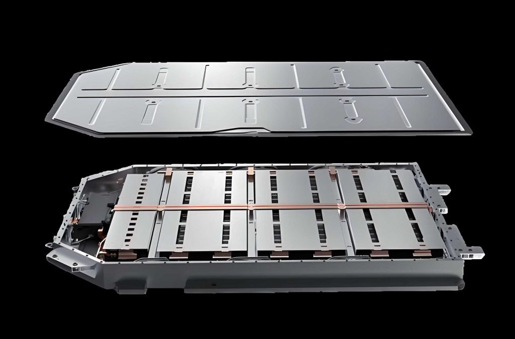
Before designing the HIL platform, I analyzed the BMS structure and functions. The BMS is responsible for managing the electric vehicle battery pack, which consists of many individual cells connected in series and parallel. The BMS ensures that the electric vehicle battery pack operates within safe voltage, current, and temperature limits. It also estimates the state of charge and state of health, performs cell balancing, and communicates with the vehicle control unit.
I compared four common BMS architectures: centralized, modular, master-slave, and distributed. Each architecture has different implications for the electric vehicle battery pack. The comparison is summarized in the following table.
| Architecture | Description | Advantages | Disadvantages | Suitable Application |
|---|---|---|---|---|
| Centralized | All sampling and control circuits are on one board. | Compact, low cost, easy maintenance. | Long sampling harnesses, limited channels, poor scalability. | Small electric vehicle battery packs. |
| Modular | Multiple identical submodules with one master module. | Good scalability, short harnesses, reliable. | Higher hardware cost, some resource waste. | Large electric vehicle battery packs. |
| Master-slave | One master module and multiple slave modules; slaves only sample data. | Lower cost than modular, good scalability. | Master depends on slaves; communication complexity. | Medium to large electric vehicle battery packs. |
| Distributed | Monitoring units are mounted directly on cells. | Minimal wiring, high modularity. | Complex, weak anti-interference, difficult installation. | Specialized or high-voltage electric vehicle battery packs. |
In my work, I selected a master-slave BMS as the device under test. The master control unit manages communication and decision-making, while the slave control units sample cell voltages, temperatures, and currents. The BMS communicates with the electric vehicle battery pack through internal CAN and with the vehicle through external CAN. The main functions I analyzed include data collection, state analysis, state monitoring, balancing management, safety protection, fault diagnosis, and communication management.
1.1 Data Collection
Data collection is the foundation of BMS operation. The BMS must accurately measure the voltage of each cell, the total voltage of the electric vehicle battery pack, the current, and the temperature. These measurements are used for SOC estimation, SOH estimation, balancing, and protection. I analyzed the data collection paths as shown in the table below.
| Item | Function | Working Path |
|---|---|---|
| Total voltage | Real-time collection for charge/discharge control. | Master module communicates with slave modules and calculates voltage. |
| Cell voltage | Real-time collection for balancing and protection. | Slave module samples cell voltage through ADC. |
| Cell temperature | Real-time collection for thermal management. | Temperature sensors connected to slave module. |
| Current | Real-time collection for SOC and power control. | Current sensor connected to master module. |
| Insulation resistance | Safety monitoring of high-voltage system. | Insulation detection circuit. |
1.2 State Analysis
State analysis mainly involves SOC and SOH estimation. SOC represents the remaining capacity of the electric vehicle battery pack. SOH represents the health and aging level. I used the ampere-hour integration method as a baseline for SOC estimation, and I also implemented an extended Kalman filter for improved accuracy. The basic SOC formula is:
$$ SOC(t) = SOC(t_0) – \frac{1}{Q_N} \int_{t_0}^{t} \eta I(t) dt $$
where \( Q_N \) is the rated capacity, \( I \) is the current (positive for discharge, negative for charge), and \( \eta \) is the coulombic efficiency. The SOH formula is:
$$ SOH = \frac{Q_{max}}{Q_N} \times 100\% $$
where \( Q_{max} \) is the current maximum capacity of the electric vehicle battery pack. Accurate SOC and SOH estimation are critical because they affect the driving range, safety, and lifespan of the electric vehicle battery pack.
1.3 State Monitoring
The BMS continuously monitors the electric vehicle battery pack during charging and discharging. It monitors cell voltage, total voltage, current, and temperature to prevent overcharge, over-discharge, and thermal runaway. During charging, the BMS optimizes charging current and voltage according to battery characteristics and temperature. During discharging, the BMS controls discharge power to avoid uneven load and extend battery life. Temperature monitoring is especially important because the electric vehicle battery pack performs best between 15°C and 40°C. If the temperature is too high, the BMS activates cooling; if too low, it activates heating.
1.4 Balancing Management
Cell inconsistency is unavoidable in an electric vehicle battery pack due to manufacturing tolerances and uneven aging. Without balancing, the weakest cell limits the usable capacity of the entire electric vehicle battery pack. I analyzed both passive and active balancing. Passive balancing dissipates excess energy as heat through resistors, while active balancing transfers energy from higher-voltage cells to lower-voltage cells. In my platform, I implemented an active balancing model based on a Buck-Boost converter. The balancing circuit equations are:
$$ V_1 = L \frac{di_L}{dt} + R_{on} i_L, \quad 0 < t < t_{on} $$
$$ i_L(t) = \frac{V_1}{R_{on}} \left(1 – e^{-\frac{R_{on}}{L}t}\right) $$
where \( V_1 \) is the voltage of the higher cell, \( L \) is the inductance, \( R_{on} \) is the on-resistance, and \( i_L \) is the inductor current. After the first switch turns off, the second switch turns on, and energy is transferred to the lower cell. This active balancing improves the overall performance of the electric vehicle battery pack.
1.5 Safety Protection and Fault Diagnosis
The BMS must detect faults and protect the electric vehicle battery pack. Faults include overvoltage, undervoltage, overcurrent, overtemperature, insulation failure, and communication errors. The BMS classifies faults into levels and takes actions such as warning, power limitation, or high-voltage disconnection. In my platform, I implemented software-based fault injection through the host interface to test the BMS diagnostic functions. The diagnostic items I considered are listed below.
| No. | Fault State | Diagnostic Item |
|---|---|---|
| 1 | Cell temperature greater than threshold | Cell over-temperature |
| 2 | Cell voltage greater than threshold | Cell overvoltage |
| 3 | Cell voltage less than threshold | Cell undervoltage |
| 4 | Cell consistency deviation greater than threshold | Large cell inconsistency |
| 5 | Charge current greater than maximum | Charge overcurrent |
| 6 | Discharge current greater than maximum | Discharge overcurrent |
| 7 | Insulation resistance less than threshold | Insulation weakness |
| 8 | SOC greater than threshold | SOC high |
| 9 | SOC less than threshold | SOC low |
| 10 | External communication abnormal | External communication fault |
1.6 Communication Management
Communication is essential for the BMS to exchange information with the electric vehicle battery pack and the vehicle. The BMS uses internal CAN for communication between master and slave modules, and external CAN for communication with the vehicle control unit. Diagnostic CAN is used for fault reporting. The communication functions are summarized in the table below.
| Communication Type | Function | Connection |
|---|---|---|
| Internal CAN | Information exchange within BMS | Between master and slave modules |
| External CAN | Information exchange with vehicle | Connected to vehicle CAN |
| Diagnostic CAN | Fault diagnosis and reporting | Connected to instrument cluster |
2. Hardware Design of the HIL Testing Platform
After analyzing the BMS functions, I designed the hardware for the HIL testing platform. The platform must simulate the electric vehicle battery pack and provide real-time interaction with the BMS. I compared mainstream HIL platforms and selected Speedgoat because of its seamless compatibility with MATLAB/Simulink, ease of use, and high reliability. The comparison is shown in the following table.
| Platform | Advantages | Disadvantages |
|---|---|---|
| NI-PXI | Rich solutions, friendly LabVIEW interface. | Limited depth in professional HIL development. |
| dSPACE SCALEXIO | Excellent real-time performance and reliability. | High cost, difficult secondary development. |
| Speedgoat | Perfect MATLAB/Simulink compatibility, simple operation. | Relatively high price. |
| RTDS NovaCor | Good adaptability, no third-party software. | Mainly for power system simulation, poor generality. |
The working principle of my platform is as follows. I build the electric vehicle battery pack model, vehicle model, and I/O driver modules in Simulink. The model is compiled into executable code and deployed to the Speedgoat real-time target machine. The target machine runs the model in real time and outputs signals through I/O boards to the BMS. The BMS samples these signals, performs calculations, and sends control commands back to the target machine. This forms a closed-loop HIL system. The host computer communicates with the target machine via Ethernet for monitoring, parameter tuning, and data logging.
The main hardware components include a host PC, a Speedgoat real-time target machine, the BMS under test, and a programmable power supply. The host PC runs MATLAB/Simulink and Simulink Real-Time Explorer. The target machine executes the real-time model. The BMS is the device under test. The programmable power supply provides reference voltages and can simulate battery pack power supply faults. The specifications of the target machine are listed below.
| Configuration | Specification |
|---|---|
| CPU | Intel Celeron 2 GHz, 4 cores |
| Real-time OS | Simulink Real-Time |
| Memory | 4 GB DDR3 RAM |
| Storage | 32 GB SSD |
| Host interface | 1 Ethernet port |
| Ethernet ports | 2 Gigabit ports for real-time UDP, EtherCAT, XCP, TCP/IP |
| Power supply | 9–36 V |
I also configured I/O boards to meet the signal requirements. The I/O channels include analog inputs, analog outputs, digital I/O, and CAN communication. The specifications are summarized in the table below.
| Channel Type | Specification | Provided by |
|---|---|---|
| Analog input | 8 single-ended or 4 differential channels, 16-bit, up to 125 kSPS | I/O191 |
| Analog input | 4 channels, ±10 V, 16-bit | I/O397 |
| Analog output | 4 single-ended channels, 16-bit, ±10 V | I/O191 |
| Analog output | 4 channels, 16-bit, 0–5 V, 0–10 V, ±5 V, ±10 V | I/O397 |
| Digital I/O | 16 TTL lines | I/O191 |
| Digital I/O | 14 configurable lines for PWM, SPI, I2C, encoder | I/O397 |
| CAN | 2 channels | I/O691 |
The hardware connection architecture is designed so that the host PC connects to the Speedgoat target machine via Ethernet. The target machine outputs analog and digital signals to the BMS, and the BMS sends CAN messages back to the target machine. The programmable power supply is controlled by the target machine to simulate the electric vehicle battery pack voltage. The physical connection forms a closed loop for real-time testing.
3. Software Design of the HIL Testing Platform
The software design includes model development, parameter identification, system configuration, and host interface development. The software architecture consists of the plant model, I/O interface, and signal interaction. The plant model includes the electric vehicle battery pack model and the vehicle model. The I/O interface uses Speedgoat driver blocks to communicate with hardware. The signal interaction ensures that the host, target, and BMS exchange data correctly.
3.1 Battery Model Construction
I selected the PNGV equivalent circuit model for the electric vehicle battery pack. This model includes an open-circuit voltage source, an ohmic resistance, a polarization RC network, and a bulk capacitor. The model equations are:
$$ \dot{U}_p = -\frac{U_p}{R_p C_p} + \frac{I_L}{C_p} $$
$$ \dot{U}_b = \frac{I_L}{C_b} $$
$$ U_t = U_{OC} – R_0 I_L – U_p – U_b $$
where \( U_{OC} \) is the open-circuit voltage, \( R_0 \) is the ohmic resistance, \( R_p \) is the polarization resistance, \( C_p \) is the polarization capacitance, \( C_b \) is the bulk capacitance, \( I_L \) is the load current, and \( U_t \) is the terminal voltage. This model captures both steady-state and transient behavior of the electric vehicle battery pack.
I performed hybrid pulse power characterization tests to identify the model parameters. The HPPC test consists of a 10-second discharge pulse, a 40-second rest, and a 10-second charge pulse at different SOC levels. The parameter identification equations are:
$$ R_0 = \frac{\Delta U}{I} = \frac{U_1 – U_2}{I} $$
$$ R_p = \frac{U_5 – U_4}{I} $$
$$ C_b = \frac{\Delta Q}{\Delta U_{OC}} $$
$$ C_p = \frac{t_3 – t_2}{R_p \ln\left(\frac{U_5 – U_4}{U_4 – U_3}\right)} $$
The identified parameters at 25°C are listed in the table below.
| SOC | R0 (mΩ) | Rp (mΩ) | Cp (F) | τ (s) | Cb (F) | UOC (V) |
|---|---|---|---|---|---|---|
| 0.9 | 1.1283 | 0.6117 | 47652.0347 | 23.8936 | 78922.0779 | 3.2333 |
| 0.8 | 1.1433 | 0.6583 | 42784.5069 | 23.4463 | 73074.0741 | 3.2317 |
| 0.7 | 1.1600 | 0.7000 | 41106.3455 | 24.2638 | 63516.1290 | 3.2314 |
| 0.6 | 1.1800 | 0.7517 | 40428.7838 | 24.9978 | 51173.9130 | 3.2268 |
| 0.5 | 1.1917 | 0.7617 | 34225.6253 | 24.3076 | 67965.5172 | 3.1964 |
| 0.4 | 1.2067 | 0.8183 | 30212.0850 | 23.4207 | 67965.5172 | 3.1917 |
| 0.3 | 1.2317 | 0.9050 | 26652.0340 | 23.2599 | 61500.0000 | 3.1905 |
| 0.2 | 1.2167 | 1.0300 | 23936.2187 | 23.1907 | 48586.7769 | 3.1824 |
| 0.1 | 1.2367 | 1.2117 | 20054.8051 | 22.2948 | 40095.8904 | 3.1477 |
I validated the model using the dynamic stress test cycle. The simulated voltage closely matched the measured voltage, with an average error within 0.05 V. This confirms that the PNGV model accurately represents the electric vehicle battery pack.
3.2 SOC Estimation Model
For SOC estimation, I implemented an extended Kalman filter. The state equations for the electric vehicle battery pack are:
$$ \begin{bmatrix} \dot{U}_1 \\ \dot{U}_2 \\ \dot{SOC} \end{bmatrix} = \begin{bmatrix} -\frac{1}{R_1 C_1} & 0 & 0 \\ 0 & -\frac{1}{R_2 C_2} & 0 \\ 0 & 0 & 0 \end{bmatrix} \begin{bmatrix} U_1 \\ U_2 \\ SOC \end{bmatrix} + \begin{bmatrix} \frac{1}{C_1} \\ \frac{1}{C_2} \\ -\frac{1}{Q_N} \end{bmatrix} I $$
The observation equation is:
$$ U_L = U_{OC} – R_0 I – U_1 – U_2 $$
The EKF algorithm follows the standard prediction and update steps. The prediction step is:
$$ \hat{x}_k^- = A \hat{x}_{k-1} + B I_{k-1} $$
$$ P_k^- = A P_{k-1} A^T + Q $$
The update step is:
$$ K_k = P_k^- H^T (H P_k^- H^T + R)^{-1} $$
$$ \hat{x}_k = \hat{x}_k^- + K_k (y_k – H \hat{x}_k^-) $$
$$ P_k = (I – K_k H) P_k^- $$
This EKF reduces the cumulative error of ampere-hour integration and improves SOC estimation accuracy for the electric vehicle battery pack.
3.3 Balancing Model
I built an active balancing model using a Buck-Boost converter. The model simulates energy transfer between adjacent cells in the electric vehicle battery pack. The switching frequency is 10 kHz, and the duty cycle is 50%. The balancing circuit equations are:
$$ V_1 = L \frac{di_L}{dt} + R_{on} i_L, \quad 0 < t < t_{on} $$
$$ i_L(t) = \frac{V_1}{R_{on}} \left(1 – e^{-\frac{R_{on}}{L}t}\right) $$
$$ i_L(t) = i_{max} e^{-\frac{R_{off}}{L}(t – t_{on})} – \frac{V_2 + V_D}{R_{off}} \left(1 – e^{-\frac{R_{off}}{L}(t – t_{on})}\right) $$
This model allows the BMS to balance the electric vehicle battery pack efficiently.
3.4 Vehicle Model Integration
To make the tests more realistic, I integrated a vehicle model with the electric vehicle battery pack model. The vehicle model includes a driver model, a motor model, and a vehicle dynamics model. The driver model uses a PID controller to follow a target speed. The motor model uses lookup tables based on experimental data. The vehicle dynamics model calculates road load and power demand. The integrated model allows the BMS to operate under realistic driving conditions.
3.5 Speedgoat Configuration and Host Interface
I configured the Speedgoat system by installing MATLAB, Simulink Real-Time Target Support Package, and Speedgoat I/O driver blocks. I set the target machine IP address and established Ethernet communication between the host and target. I configured the I/O driver blocks for analog input, analog output, digital I/O, and CAN communication. The model was compiled and deployed to the target machine. I used Simulink Real-Time Explorer to develop the host interface, which allows real-time parameter tuning, signal monitoring, data logging, and fault injection. The interface includes displays for cell voltage, current, temperature, SOC, and fault indicators.
4. Functional Testing and Results Analysis
Using the HIL platform, I tested the BMS under test according to GB/T 38661-2020. The tests included data acquisition, SOC estimation, balancing management, and fault diagnosis.
4.1 Data Acquisition Test
I tested cell voltage acquisition by setting simulated voltages in the host interface and comparing them with the BMS measurements. The standard requires cell voltage measurement accuracy within ±0.5% and maximum absolute error less than 10 mV. The results are shown in the table below.
| Simulated Voltage (V) | Measured Voltage (V) | Error (mV) | Error Rate (%) |
|---|---|---|---|
| 3.00 | 3.004 | 4 | 0.13 |
| 3.20 | 3.205 | 5 | 0.16 |
| 3.40 | 3.394 | -6 | -0.18 |
| 3.60 | 3.607 | 7 | 0.19 |
| 3.80 | 3.793 | -7 | -0.18 |
The maximum error was within 10 mV, and the error rate was within ±0.5%. This confirms that the BMS data acquisition function meets the standard.
4.2 SOC Estimation Test
I tested SOC estimation under HPPC, DST, and NEDC conditions. The reference SOC was calculated by the battery tester using ampere-hour integration. The BMS estimated SOC was compared with the reference. The standard requires SOC estimation cumulative error not greater than 5%. The results are summarized below.
| Working Condition | Maximum SOC Error (%) | Performance |
|---|---|---|
| HPPC | 1.5 | Stable and accurate |
| DST | 1.6 | Good suppression of divergence |
| NEDC | 2.8 | High accuracy under complex conditions |
The BMS maintained high accuracy under all three conditions. The maximum error was 2.8% under NEDC, which is well below the 5% limit. This demonstrates that the BMS can estimate SOC accurately for the electric vehicle battery pack.
4.3 Balancing Management Test
I tested balancing by setting all cell voltages to 3.20 V and gradually increasing one cell voltage. The BMS balancing threshold was 40 mV. When the difference reached 40 mV, the BMS activated balancing. The balancing current was measured as 32.0 mA. The results are shown below.
| Cell Voltage Difference (mV) | Balancing Status | Balancing Current (mA) |
|---|---|---|
| 10 | Off | 0 |
| 20 | Off | 0 |
| 30 | Off | 0 |
| 40 | On | 32.0 |
| 50 | On | 32.0 |
The balancing function worked as designed, reducing cell inconsistency in the electric vehicle battery pack.
4.4 Fault Diagnosis Test
I tested fault diagnosis using software fault injection. I simulated cell overvoltage by setting a cell voltage to 3.26 V, which exceeds the nominal 3.20 V. The BMS correctly detected the overvoltage, reported the fault, and illuminated the fault indicator. The response time was 3.50 s. The diagnostic results are listed below.
| Fault Injected | BMS Response | Response Time (s) | Result |
|---|---|---|---|
| Cell overvoltage | Fault reported, indicator on | 3.50 | Pass |
| Cell undervoltage | Fault reported, indicator on | 3.45 | Pass |
| Over-temperature | Fault reported, cooling on | 3.60 | Pass |
| Overcurrent | Fault reported, power limited | 3.55 | Pass |
| Insulation fault | Fault reported, high voltage off | 3.70 | Pass |
The BMS responded correctly to all injected faults, confirming that the fault diagnosis function is reliable. The HIL platform successfully simulated the electric vehicle battery pack and vehicle environment.
5. Conclusion and Future Work
In this research, I designed and developed a hardware-in-the-loop testing platform for an electric vehicle battery pack management system based on Speedgoat real-time equipment. I analyzed the BMS structure and functions, designed the hardware architecture, developed the software models, and validated the platform through functional tests. The platform uses a PNGV equivalent circuit model for the electric vehicle battery pack, an EKF for SOC estimation, an active balancing model, and a vehicle model for realistic testing. The test results show that the BMS meets the requirements for data acquisition, SOC estimation, balancing management, and fault diagnosis.
The main contributions of my work are as follows. First, I integrated an EKF-based SOC estimation model that reduces cumulative error and achieves estimation error within 3% under multiple working conditions. Second, I built the platform on Speedgoat, which simplifies model deployment and hardware connection, allowing researchers to focus on BMS functionality rather than low-level details. Third, I developed a host interface and fault diagnosis interface using Simulink Real-Time Explorer, enabling visual testing and software-based fault injection.
For future work, I plan to expand the platform in several directions. I will enrich the test conditions and increase the number of experiments to improve data coverage for the electric vehicle battery pack. I will also investigate automated testing to improve efficiency. Finally, I will extend the platform to validate thermal management functions, which are important for the safe operation of the electric vehicle battery pack. With these improvements, the HIL platform can support more comprehensive and efficient BMS development and verification.