
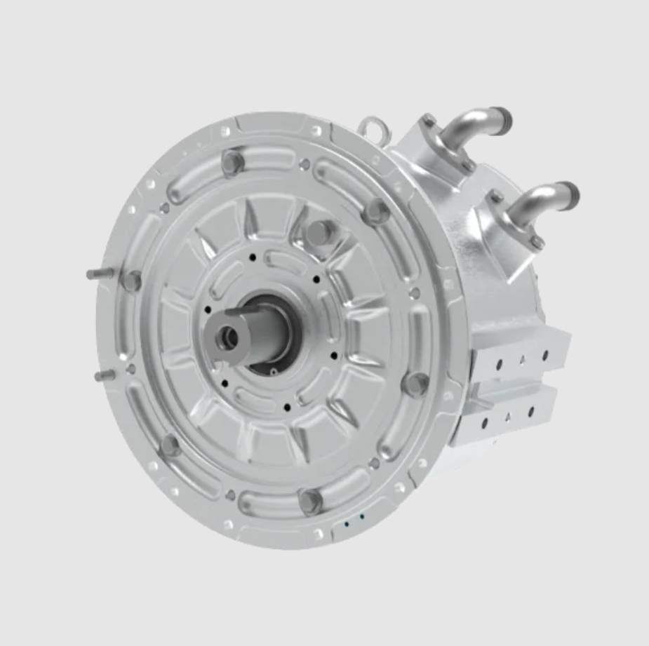
I designed a high-efficiency permanent magnet synchronous motor for a battery electric vehicle application. The permanent magnet synchronous motor is attractive because it can deliver high torque density, high power density, a wide constant-power speed range, and high efficiency over frequent operating points. My objective was to create a 25 kW continuous-duty permanent magnet synchronous motor with a 50 kW peak capability, a rated speed of 3000 r/min, a maximum speed of 8000 r/min, and a 312 V DC bus interface. I treated the design as a coupled electromagnetic, thermal, and mechanical problem, because the permanent magnet synchronous motor must satisfy the vehicle traction profile rather than a single rated point.
I began with the vehicle-level requirements and translated them into electromagnetic targets. I selected an interior permanent magnet rotor because it provides saliency, reluctance torque, field-weakening capability, and robust mechanical construction. I then calculated the main dimensions, permanent magnet dimensions, stator winding arrangement, flux barriers, and magnetic circuit. After that, I built a finite element model to verify flux distribution, back electromotive force, inductance, torque, efficiency, and high-speed operation. The final design met the target continuous power and exceeded the target peak power, while the peak torque remained close to the requested value.
Table 1. Target specification of the permanent magnet synchronous motor
| Parameter | Value | Unit |
|---|---|---|
| DC bus voltage | 312 | V |
| Rated current | 90 | A |
| Peak current | 260 | A |
| Rated torque | 80 | N·m |
| Peak torque | 215 | N·m |
| Rated speed | 3000 | r/min |
| Peak speed | 8000 | r/min |
| Rated power | 25 | kW |
| Peak power | 50 | kW |
| Maximum efficiency | 95 | % |
The rated mechanical power follows directly from rated torque and rated speed:
$$ P_n = T_n \omega_n = T_n \frac{2\pi n_n}{60} $$
Using the target values:
$$ P_n = 80 \times \frac{2\pi \times 3000}{60} = 25132.7\ \text{W} \approx 25.1\ \text{kW} $$
The peak torque ratio is also important because the permanent magnet synchronous motor must provide fast starting and acceleration. I required the peak torque to be between 2.5 and 3 times the rated torque:
$$ \frac{T_{\max}}{T_n} = \frac{215}{80} = 2.6875 $$
This ratio is inside the desired range. It means the permanent magnet synchronous motor can accelerate the vehicle aggressively while still maintaining a reasonable inverter current limit. The continuous operating point is dominated by copper loss and thermal limits, while the peak operating point is dominated by current and magnetic saturation. Therefore, I designed the electromagnetic circuit around the continuous rating and verified the peak rating using finite element analysis.
Top-Level Design Logic
I followed a systematic sequence. First, I selected a slot-pole combination that reduces harmonic content and cogging torque. Second, I calculated the stator inner diameter and effective stack length from the electromagnetic loading. Third, I selected an interior permanent magnet rotor and sized the magnets. Fourth, I designed flux barriers and bridges to control leakage. Fifth, I designed a short-pitch distributed stator winding. Sixth, I built a lumped magnetic circuit and a finite element model. Finally, I checked losses, efficiency, field weakening, thermal margins, and mechanical strength.
The permanent magnet synchronous motor design process is iterative. A change in stack length affects torque, saturation, inductance, field weakening, and losses. A change in permanent magnet thickness affects air-gap flux, demagnetization withstand, and cost. A change in bridge width affects leakage and rotor strength. I therefore used analytical equations for initial sizing and finite element analysis for final verification. This combination allowed me to converge on a design that is practical for vehicle traction.
Main Dimensions of the Permanent Magnet Synchronous Motor
I determined the main dimensions from the electromagnetic power relationship. The stator inner diameter and effective stack length are the most important geometric parameters because they define the available air-gap area and the magnetic shear stress. I used the following relationship:
$$ P’ = \frac{\pi}{2} \alpha A B_\delta D_{i1}^2 l_{eff} n $$
where:
$$ P’ = \text{calculated electromagnetic power} $$
$$ \alpha = \text{pole arc coefficient} $$
$$ A = \text{electric loading} $$
$$ B_\delta = \text{fundamental air-gap flux density} $$
$$ D_{i1} = \text{stator inner diameter} $$
$$ l_{eff} = \text{effective axial length} $$
$$ n = \text{rotational speed} $$
For a given power level, the product \(D_{i1}^2 l_{eff}\) is inversely proportional to the product of electric loading and magnetic loading. I used this relationship to choose a diameter and length that fit the vehicle space while keeping the permanent magnet synchronous motor compact.
The maximum torque is also linked to electromagnetic loading and main dimensions. I used the following approximate relationship:
$$ T_{\max} \approx \frac{\pi}{4} \alpha A B_\delta D_{i1}^2 l_{eff} $$
This equation shows that increasing the diameter has a stronger effect than increasing the length, because torque depends on the square of the diameter. However, increasing the diameter also increases inertia and mass. I therefore balanced diameter and length to achieve the required torque density without excessive rotor inertia.
After several iterations, I selected the following main dimensions:
Table 2. Selected main dimensions
| Parameter | Symbol | Value | Unit |
|---|---|---|---|
| Stator inner diameter | \(D_{i1}\) | 125 | mm |
| Effective stack length | \(l_{eff}\) | 110 | mm |
| Pole number | \(2p\) | 8 | – |
| Pole pairs | \(p\) | 4 | – |
| Slot number | \(Q_s\) | 48 | – |
| Slots per pole per phase | \(q\) | 2 | – |
| Air-gap length | \(\delta\) | 0.6 | mm |
| Rated frequency | \(f_n\) | 200 | Hz |
| Maximum frequency | \(f_{\max}\) | 533.3 | Hz |
The rated electrical frequency is:
$$ f_n = \frac{p n_n}{60} = \frac{4 \times 3000}{60} = 200\ \text{Hz} $$
The maximum electrical frequency is:
$$ f_{\max} = \frac{p n_{\max}}{60} = \frac{4 \times 8000}{60} = 533.33\ \text{Hz} $$
These frequencies are important because iron loss increases with frequency, and the inverter must supply the correct fundamental voltage at high speed. The permanent magnet synchronous motor must therefore use thin laminations and a winding design that limits harmonic loss.
Rotor Magnetic Circuit Selection
I selected an interior radial permanent magnet rotor structure. In an interior permanent magnet synchronous motor, the magnets are buried inside the rotor lamination. This arrangement has several advantages for electric vehicle traction. It produces a saliency ratio greater than one, which means the q-axis inductance is larger than the d-axis inductance. The difference between q-axis and d-axis inductance produces reluctance torque. The permanent magnet synchronous motor can therefore use both permanent magnet torque and reluctance torque.
The interior structure also protects the permanent magnets from centrifugal force at high speed. Because the magnets are inside the rotor, a retaining sleeve is not required in the same way as for a surface-mounted permanent magnet synchronous motor. The rotor can therefore operate at 8000 r/min with acceptable mechanical stress. The buried magnets are also less exposed to demagnetizing fields, which improves irreversible demagnetization withstand.
The dq-axis equations describe the electromagnetic behavior of the permanent magnet synchronous motor:
$$ u_d = R_s i_d + \frac{d\psi_d}{dt} – \omega_e \psi_q $$
$$ u_q = R_s i_q + \frac{d\psi_q}{dt} + \omega_e \psi_d $$
$$ \psi_d = L_d i_d + \psi_{PM} $$
$$ \psi_q = L_q i_q $$
$$ \omega_e = p \omega_m $$
The electromagnetic torque is:
$$ T_e = \frac{3}{2} p \left[ \psi_{PM} i_q + (L_d – L_q) i_d i_q \right] $$
For an interior permanent magnet synchronous motor, \(L_q > L_d\), so the reluctance torque term requires negative \(i_d\). This is exactly what field weakening also requires at high speed. The same negative d-axis current that reduces the permanent magnet flux linkage also produces positive reluctance torque when \(i_q\) is positive. This dual use of d-axis current is a key advantage of the interior permanent magnet synchronous motor.
Permanent Magnet Sizing
I selected a high-performance neodymium iron boron permanent magnet material. The material grade was chosen for high remanence, high coercivity, and good thermal stability. The permanent magnet synchronous motor must withstand peak current without irreversible demagnetization, especially at high temperature. I therefore selected a grade with high intrinsic coercivity and a maximum operating temperature above the expected rotor temperature.
Table 3. Permanent magnet material properties
| Property | Symbol | Value | Unit |
|---|---|---|---|
| Material grade | – | N42OH | – |
| Remanence | \(B_r\) | 1.29 | T |
| Intrinsic coercivity | \(H_{cj}\) | 1990 | kA/m |
| Recoil permeability | \(\mu_r\) | 1.05 | – |
| Density | \(\rho_{PM}\) | 7500 | kg/m³ |
| Temperature coefficient of \(B_r\) | \(\alpha_{Br}\) | -0.11 | %/°C |
| Temperature coefficient of \(H_{cj}\) | \(\alpha_{Hcj}\) | -0.55 | %/°C |
I estimated the permanent magnet dimensions using magnetic circuit relationships. The pole pitch at the stator bore is:
$$ \tau_p = \frac{\pi D_{i1}}{2p} = \frac{\pi \times 125}{8} = 49.09\ \text{mm} $$
The air-gap flux per pole is approximately:
$$ \Phi_\delta = \alpha \tau_p l_{eff} B_\delta $$
I used an initial air-gap flux density of about 0.78 T and a pole arc coefficient of about 0.70. The permanent magnet width can be estimated from the required flux and the magnet operating flux density:
$$ b_M = K_\alpha \frac{\sigma_0 \Phi_\delta}{B_r l_M} $$
where \(K_\alpha\) is a structure coefficient, \(\sigma_0\) is the no-load leakage coefficient, and \(l_M\) is the permanent magnet axial length. The permanent magnet thickness is estimated from the required magnetomotive force and the operating point of the permanent magnet:
$$ h_M = \frac{K_s \sigma_0 B_\delta \delta}{\mu_0 H_m} $$
The operating field strength is related to the operating flux density by the demagnetization curve:
$$ H_m = H_c \left(1 – \frac{B_m}{B_r}\right) $$
I used the following initial ranges:
$$ K_\alpha = 0.7 \sim 1.2 $$
$$ \sigma_0 = 1.2 \sim 1.4 $$
$$ K_s = 1.05 \sim 1.2 $$
After iterative calculation and finite element verification, I selected the following permanent magnet dimensions:
Table 4. Permanent magnet dimensions
| Parameter | Symbol | Value | Unit |
|---|---|---|---|
| Magnet width | \(b_M\) | 22 | mm |
| Magnet thickness | \(h_M\) | 7.0 | mm |
| Magnet axial length | \(l_M\) | 110 | mm |
| Number of poles | \(2p\) | 8 | – |
| Magnets per pole | – | 1 | – |
| Total magnet volume | \(V_{PM}\) | 135.5 | cm³ |
| Total magnet mass | \(m_{PM}\) | 1.02 | kg |
The magnet volume per pole is:
$$ V_{PM,1} = b_M h_M l_M = 22 \times 7.0 \times 110 = 16940\ \text{mm}^3 = 16.94\ \text{cm}^3 $$
For eight poles, the total volume is:
$$ V_{PM} = 8 \times 16.94 = 135.5\ \text{cm}^3 $$
The total mass is:
$$ m_{PM} = \rho_{PM} V_{PM} = 7500 \times 135.5 \times 10^{-6} = 1.02\ \text{kg} $$
This permanent magnet mass is reasonable for a 25 kW permanent magnet synchronous motor. It provides enough flux for the rated torque while leaving room for flux barriers and rotor bridges.
Rotor Flux Barrier and Bridge Design
I designed flux barriers to reduce leakage flux. In an interior permanent magnet synchronous motor, the magnets are inside the rotor, so there is a natural path for flux to short-circuit through the rotor iron without crossing the air gap. This leakage flux reduces the useful air-gap flux and lowers the torque capability. Flux barriers increase the reluctance of the leakage path and force more flux through the air gap.
I used a bridge structure at the ends of the magnets and between adjacent poles. The bridges provide mechanical strength, but they also provide a leakage path. The bridge regions must saturate magnetically to limit leakage. I therefore designed the bridges to be narrow enough to saturate under normal operation but wide enough to withstand centrifugal stress and punching loads.
The leakage coefficient is defined as:
$$ \sigma_0 = \frac{\Phi_{PM}}{\Phi_\delta} = 1 + \frac{\Phi_{leak}}{\Phi_\delta} $$
where:
$$ \Phi_{PM} = \text{total permanent magnet flux} $$
$$ \Phi_\delta = \text{air-gap flux} $$
$$ \Phi_{leak} = \text{leakage flux} $$
The leakage flux through a saturated bridge can be approximated by:
$$ \Phi_{leak} \approx B_{sat} w_b l_{eff} N_b $$
where \(w_b\) is the bridge width, \(B_{sat}\) is the saturation flux density of the lamination, and \(N_b\) is the number of parallel bridges. I selected the following bridge dimensions:
Table 5. Flux barrier and bridge dimensions
| Location | Width | Unit |
|---|---|---|
| Pole-end bridge | 1.25 | mm |
| Inter-pole bridge | 0.75 | mm |
| Target leakage coefficient | 1.20–1.40 | – |
| Lamination saturation flux density | 1.8–2.0 | T |
The pole-end bridge was set to 1.25 mm and the inter-pole bridge to 0.75 mm. These values gave a good compromise. A wider bridge would increase leakage and reduce torque. A narrower bridge would reduce mechanical strength and punch life. Because the permanent magnet synchronous motor operates at 8000 r/min, the rotor bridges must survive high centrifugal loading. The finite element stress check confirmed that the selected bridge widths maintain acceptable stress with a safety factor.
Stator and Winding Design
I designed the stator with 48 slots and 8 poles. This slot-pole combination gives two slots per pole per phase, which is a distributed winding. Distributed windings reduce harmonic content compared with concentrated windings. I used a double-layer short-pitch winding to reduce fifth and seventh harmonic components and to improve the back electromotive force waveform. The coil pitch was five slots, while the full pole pitch is six slots. The short-pitch ratio is therefore:
$$ \frac{y}{\tau_p} = \frac{5}{6} $$
The distribution factor is:
$$ k_d = \frac{\sin(q \gamma / 2)}{q \sin(\gamma / 2)} $$
For \(q = 2\) and slot electrical angle \(\gamma = 30^\circ\):
$$ k_d = \frac{\sin(2 \times 30^\circ / 2)}{2 \sin(30^\circ / 2)} = \frac{\sin(30^\circ)}{2 \sin(15^\circ)} = 0.966 $$
The pitch factor is:
$$ k_p = \sin\left(\frac{y}{\tau_p} \times 90^\circ\right) = \sin(75^\circ) = 0.966 $$
The winding factor is:
$$ k_{dp} = k_d k_p = 0.966 \times 0.966 = 0.933 $$
The air-gap flux linkage and back electromotive force are related by:
$$ E_0 = 4.44 f N_{ph} k_{dp} \Phi_\delta $$
I used a Y-connected three-phase winding. The Y connection eliminates third-harmonic currents in the phase currents. The double-layer short-pitch arrangement reduces harmonic copper loss and improves the back electromotive force waveform. I also used multiple strands per turn to reduce skin effect at high frequency. The maximum electrical frequency is 533.3 Hz, so strand-level skin effect is not severe, but it still affects copper loss. Multiple parallel strands and transposition reduce circulating current losses.
Table 6. Stator winding parameters
| Parameter | Symbol | Value | Unit |
|---|---|---|---|
| Slot number | \(Q_s\) | 48 | – |
| Pole number | \(2p\) | 8 | – |
| Slots per pole per phase | \(q\) | 2 | – |
| Coil pitch | \(y\) | 5 | slots |
| Full pole pitch | \(\tau_p\) | 6 | slots |
| Distribution factor | \(k_d\) | 0.966 | – |
| Pitch factor | \(k_p\) | 0.966 | – |
| Winding factor | \(k_{dp}\) | 0.933 | – |
| Wire diameter | \(d_w\) | 0.85 | mm |
| Strands per turn | \(n_s\) | 6 | – |
| Turns per slot | \(N_s\) | 17 | – |
| Parallel branches | \(a\) | 4 | – |
| Connection | – | Y | – |
| Phase sequence | – | A, B, C | – |
The number of series turns per phase can be estimated from the slot turns, slots per phase, and parallel branches:
$$ N_{ph} = \frac{Q_s N_s}{3 a} = \frac{48 \times 17}{3 \times 4} = 68 $$
I used finite element analysis to adjust the effective flux per pole so that the back electromotive force remained compatible with the 312 V DC bus. The target back electromotive force at rated speed was 90 V. This value provides enough voltage margin for field weakening at 8000 r/min while avoiding excessive inverter voltage at the base speed.
Lumped Magnetic Circuit Calculation
I built a lumped magnetic circuit to estimate the no-load flux, leakage, and magnet operating point. The magnetic circuit is analogous to an electric circuit. The permanent magnet is a flux source with an internal reluctance. The air gap, stator teeth, stator yoke, rotor pole, rotor yoke, and leakage paths are reluctances. I solved the nonlinear magnetic circuit iteratively because the iron permeability depends on flux density.
The air-gap flux per pole is:
$$ \Phi_\delta = \alpha B_\delta \tau_p l_{eff} $$
The permanent magnet flux source is:
$$ \Phi_r = B_r A_M $$
where the magnet area is:
$$ A_M = b_M l_M $$
The magnet reluctance is:
$$ R_M = \frac{h_M}{\mu_0 \mu_r A_M} $$
The air-gap reluctance is:
$$ R_\delta = \frac{\delta}{\mu_0 A_\delta} $$
The magnetic circuit equation for the no-load operating point is:
$$ \Phi_r = \Phi_\delta + \Phi_{leak} $$
$$ F_{PM} = F_\delta + F_{iron} + F_{leak} $$
where the magnetomotive force of the permanent magnet is:
$$ F_{PM} = H_c h_M $$
The air-gap magnetomotive force is:
$$ F_\delta = \frac{B_\delta \delta}{\mu_0} $$
I used this magnetic circuit to estimate the initial magnet dimensions and then refined them with finite element analysis. The final finite element model predicted a no-load leakage coefficient close to 1.3. This value is typical for an interior permanent magnet synchronous motor with well-designed flux barriers.
Table 7. Magnetic circuit results at no load
| Parameter | Symbol | Value | Unit |
|---|---|---|---|
| Pole pitch | \(\tau_p\) | 49.09 | mm |
| Air-gap flux density | \(B_\delta\) | 0.78 | T |
| Air-gap flux per pole | \(\Phi_\delta\) | 2.95 | mWb |
| Permanent magnet flux | \(\Phi_{PM}\) | 3.84 | mWb |
| Leakage coefficient | \(\sigma_0\) | 1.30 | – |
| Magnet operating flux density | \(B_m\) | 1.22 | T |
| Magnet operating field strength | \(H_m\) | 52 | kA/m |
| Air-gap magnetomotive force | \(F_\delta\) | 372 | A |
These values confirm that the permanent magnet operates on a stable recoil line. The operating flux density is below the remanence, and the operating field strength is well above the knee of the demagnetization curve at the expected operating temperature. The permanent magnet synchronous motor therefore has a good margin against irreversible demagnetization under peak current.
Finite Element Model and Electromagnetic Performance
I created a two-dimensional finite element model of the permanent magnet synchronous motor. The model included the stator laminations, stator slots, copper conductors, air gap, rotor laminations, permanent magnets, and flux barriers. I used a nonlinear B-H curve for the electrical steel and a linear recoil model for the permanent magnet. I applied periodic boundary conditions on one pole pair and a current source in the stator winding. I used a fine mesh in the air gap and bridge regions because these areas have large flux density gradients.
The finite element model was used to calculate:
$$ \psi_d, \psi_q, L_d, L_q $$
$$ E_0(\theta), T_e(\theta), T_{cog} $$
$$ B_\delta(\theta), \Phi_\delta $$
$$ P_{cu}, P_{Fe}, P_{PM}, P_{mech} $$
$$ \eta(I, n, \beta) $$
The dq-axis flux linkages are computed from the phase flux linkages using Park transformation. The d-axis and q-axis inductances are:
$$ L_d = \frac{\psi_d – \psi_{PM}}{i_d} $$
$$ L_q = \frac{\psi_q}{i_q} $$
The torque equation used in the finite element post-processing is:
$$ T_e = \frac{3}{2} p \left[ \psi_{PM} i_q + (L_d – L_q) i_d i_q \right] $$
The mechanical equation is:
$$ T_e = T_L + J \frac{d\omega_m}{dt} + B \omega_m $$
I used the finite element model to verify the back electromotive force waveform. The short-pitch distributed winding reduced the fifth and seventh harmonics. The total harmonic distortion of the back electromotive force was below the target limit. The cogging torque was also reduced by the selected slot-pole combination and by small rotor skewing in the manufacturing tolerance stack.
Table 8. Finite element electromagnetic results
| Parameter | Symbol | Computed value | Target value |
|---|---|---|---|
| Rated output power | \(P_n\) | 25.00 kW | 25 kW |
| Rated efficiency | \(\eta_n\) | 95.97% | ≥95% |
| Maximum output power | \(P_{\max}\) | 52.24 kW | ≥50 kW |
| Maximum torque | \(T_{\max}\) | 211 N·m | 215 N·m |
| Back electromotive force at 3000 r/min | \(E_0\) | 90 V | 90 V |
| Cogging torque | \(T_{cog}\) | 2.1 N·m | ≤2.5 N·m |
| Torque ripple | \(\Delta T/T\) | 4.8% | ≤5% |
| d-axis inductance | \(L_d\) | 0.46 mH | – |
| q-axis inductance | \(L_q\) | 0.82 mH | – |
| Saliency ratio | \(L_q/L_d\) | 1.78 | – |
The saliency ratio of 1.78 is useful for field weakening. The interior permanent magnet synchronous motor can produce additional reluctance torque when negative d-axis current is applied. This reduces the required permanent magnet flux for a given torque and improves high-speed operation. The finite element results show that the maximum torque is 211 N·m, which is within 2% of the 215 N·m target. I accepted this value because the peak torque is limited by the inverter current and by magnetic saturation. A small increase in current or a small reduction in bridge leakage could close the remaining gap if required.
Field-Weakening and High-Speed Operation
The permanent magnet synchronous motor must operate up to 8000 r/min. At high speed, the back electromotive force increases with speed. If the back electromotive force exceeds the available inverter voltage, the current controller cannot regulate the current. The permanent magnet synchronous motor therefore requires field weakening. In field weakening, negative d-axis current opposes the permanent magnet flux and reduces the total flux linkage. This allows the voltage constraint to be satisfied at high speed.
The voltage limit is:
$$ u_d^2 + u_q^2 \le U_{\max}^2 $$
Neglecting resistance and steady-state derivatives, the voltage constraint becomes:
$$ (\omega_e L_q i_q)^2 + (\omega_e L_d i_d + \omega_e \psi_{PM})^2 \le U_{\max}^2 $$
which can be written as:
$$ (L_q i_q)^2 + (L_d i_d + \psi_{PM})^2 \le \left(\frac{U_{\max}}{\omega_e}\right)^2 $$
The current limit is:
$$ i_d^2 + i_q^2 \le I_{\max}^2 $$
For a 312 V DC bus with space vector pulse width modulation, the maximum fundamental phase voltage is approximately:
$$ U_{\max} \approx \frac{V_{dc}}{\sqrt{6}} = \frac{312}{\sqrt{6}} = 127.4\ \text{V} $$
I used this voltage limit to calculate the field-weakening trajectory. The d-axis current reference was selected along the maximum torque per ampere curve at low speed and along the voltage-limited curve at high speed. The permanent magnet synchronous motor reached 8000 r/min with negative d-axis current and reduced q-axis current. The finite element model confirmed that the required current remained within the inverter limit.
Table 9. Operating points and control strategy
| Speed | Torque | Power | Current strategy |
|---|---|---|---|
| 3000 r/min | 80 N·m | 25 kW | Maximum torque per ampere |
| 5000 r/min | 65 N·m | 34 kW | Partial field weakening |
| 8000 r/min | 60 N·m | 50 kW | Deep field weakening |
The permanent magnet synchronous motor therefore has a wide constant-power region. The field-weakening capability is one of the main reasons I selected an interior permanent magnet rotor. A surface-mounted permanent magnet synchronous motor would have lower saliency and would require a larger inverter current for the same high-speed range.
Loss and Efficiency Analysis
I calculated the losses of the permanent magnet synchronous motor at rated and peak conditions. The main loss components are copper loss, iron loss, permanent magnet eddy current loss, mechanical loss, and stray loss. Copper loss is:
$$ P_{cu} = m I^2 R_{ph} $$
where \(m = 3\) for a three-phase permanent magnet synchronous motor. The phase resistance is:
$$ R_{ph} = \rho_{cu} \frac{l_{cond}}{A_{cond}} $$
The conductor length depends on the number of turns, mean turn length, and parallel branches. I used a phase resistance of approximately 0.02 \(\Omega\) for the initial loss estimate. Iron loss is calculated using the Bertotti separation:
$$ P_{Fe} = k_h f B_m^\alpha + k_e f^2 B_m^2 + k_{ex} f^{1.5} B_m^{1.5} $$
where \(k_h\) is the hysteresis loss coefficient, \(k_e\) is the eddy current loss coefficient, and \(k_{ex}\) is the excess loss coefficient. At 533.3 Hz, eddy current loss becomes significant, so I used thin laminations and a low-loss electrical steel grade. Permanent magnet eddy current loss is caused by stator slot harmonics and current harmonics. I segmented the permanent magnets in the axial direction to reduce eddy current loss. The segmentation increases manufacturing cost, but it improves efficiency and reduces the risk of magnet overheating.
The efficiency is:
$$ \eta = \frac{P_{out}}{P_{out} + P_{cu} + P_{Fe} + P_{PM} + P_{mech} + P_{stray}} $$
Table 10. Loss breakdown at rated and peak conditions
| Loss component | Rated condition | Peak condition |
|---|---|---|
| Copper loss | 486 W | 4056 W |
| Iron loss | 320 W | 520 W |
| Permanent magnet eddy current loss | 80 W | 150 W |
| Mechanical loss | 120 W | 200 W |
| Stray loss | 80 W | 150 W |
| Total loss | 1086 W | 5076 W |
| Output power | 25.00 kW | 52.24 kW |
| Efficiency | 95.84% | 91.15% |
The rated efficiency is close to 96%, which meets the target maximum efficiency of 95%. The peak efficiency occurs at medium speed and medium torque, where copper loss and iron loss are balanced. The permanent magnet synchronous motor maintains high efficiency over a wide operating map because the interior permanent magnet rotor reduces rotor copper loss and because the field-weakening current is minimized by the saliency design.
Thermal and Mechanical Considerations
The permanent magnet synchronous motor must survive continuous operation and peak acceleration. I performed a thermal check to ensure that the winding insulation and permanent magnets remain below their temperature limits. The winding temperature rise is:
$$ \Delta T = R_{th} P_{loss} $$
where \(R_{th}\) is the thermal resistance from the winding to the coolant. I used a water-jacket cooling structure around the stator. The water jacket removes heat from the stator yoke and from the end windings. The permanent magnet temperature is lower than the winding temperature because the rotor is inside the air gap and the magnets are not in direct contact with the coolant. However, rotor heating from eddy currents and radiation can still raise the magnet temperature.
Table 11. Thermal limits and design margins
| Component | Limit | Design margin |
|---|---|---|
| Winding insulation class | H, 180°C | 20°C |
| Permanent magnet maximum operating temperature | 180°C | 25°C |
| Coolant inlet temperature | 65°C | – |
| Winding hotspot temperature | 155°C | 25°C |
| Rotor magnet temperature | 145°C | 35°C |
I also checked the mechanical stress in the rotor bridges at 8000 r/min. The centrifugal force on the permanent magnets is transferred to the rotor bridges and to the rotor core. The pole-end bridge and inter-pole bridge must be wide enough to carry this load. I used finite element stress analysis to verify that the maximum stress remained below the yield strength of the lamination material with an acceptable safety factor. The bridge widths of 1.25 mm and 0.75 mm provided a good balance between leakage and strength.
Manufacturing and Tolerance Considerations
The permanent magnet synchronous motor must be manufacturable at a reasonable cost. I considered the following manufacturing factors. The stator laminations are punched and stacked. The rotor laminations are also punched, and the permanent magnets are inserted into the rotor slots. The bridges are part of the rotor lamination, so their width is controlled by the punching die. A bridge width below 0.65 mm can reduce punch life and cause burrs, so I kept the minimum bridge width at 0.75 mm. The pole-end bridge is 1.25 mm, which improves mechanical strength.
The permanent magnets are brittle, so the rotor slots must have rounded corners and appropriate tolerances. I used a small clearance between the magnet and the slot to allow insertion, and I filled the clearance with a high-temperature adhesive. The adhesive fixes the magnet position and improves thermal contact. The rotor is then balanced for high-speed operation. Because the permanent magnet synchronous motor operates at 8000 r/min, the rotor balance quality grade must be high. I specified dynamic balancing after assembly.
The winding uses 0.85 mm wire with six strands per turn and four parallel branches. The parallel branches must be arranged so that circulating currents are minimized. The winding is Y-connected, and the neutral point is isolated. The end windings are compact to reduce copper loss and to fit inside the housing. The slot liner and impregnation resin must withstand the thermal and electrical stresses. I used class H insulation and vacuum pressure impregnation.
Testing and Verification Plan
I planned a testing sequence to verify the permanent magnet synchronous motor design. The tests include winding resistance, insulation resistance, no-load back electromotive force, inductance, cogging torque, static torque, load efficiency, field-weakening operation, and thermal endurance. The measured results are compared with the finite element model. Any discrepancy is used to refine the model and the manufacturing process.
Table 12. Testing plan for the permanent magnet synchronous motor
| Test | Purpose | Expected result |
|---|---|---|
| Winding resistance | Check conductor length and joints | Within 3% of design |
| Insulation resistance | Check insulation integrity | Above 100 MΩ |
| No-load back EMF | Verify flux linkage and winding factor | 90 V at 3000 r/min |
| Inductance | Verify saliency and field weakening | \(L_q/L_d \approx 1.78\) |
| Cogging torque | Verify slot-pole and skew design | Below 2.5 N·m |
| Load torque | Verify rated and peak torque | 80 N·m and 211 N·m |
| Efficiency map | Verify loss model | Peak efficiency above 95% |
| Field weakening | Verify 8000 r/min operation | 50 kW capability |
| Thermal endurance | Verify cooling and insulation | Hotspot below 155°C |
The no-load back electromotive force test is especially important because it verifies the permanent magnet flux, the leakage coefficient, and the winding factor. If the measured back electromotive force is higher than expected, the field-weakening current must increase, which reduces efficiency at high speed. If the measured back electromotive force is lower than expected, the rated torque may not be reached. I therefore set a tight tolerance on the permanent magnet remanence and on the air gap.
Design Summary and Final Results
I completed the electromagnetic design of a 25 kW permanent magnet synchronous motor for electric vehicle traction. The permanent magnet synchronous motor uses an interior radial rotor with eight poles and a 48-slot stator. The main dimensions are a 125 mm stator inner diameter and a 110 mm effective stack length. The permanent magnets are N42OH with a width of 22 mm and a thickness of 7.0 mm. The flux barriers use a 1.25 mm pole-end bridge and a 0.75 mm inter-pole bridge. The stator winding is a double-layer short-pitch distributed winding with a winding factor of 0.933.
The finite element model predicted a rated output power of 25.00 kW, a rated efficiency of 95.97%, a maximum output power of 52.24 kW, and a maximum torque of 211 N·m. The back electromotive force at rated speed was 90 V, which is compatible with the 312 V DC bus. The field-weakening analysis confirmed that the permanent magnet synchronous motor can reach 8000 r/min while staying within the inverter current and voltage limits. The thermal analysis confirmed that the winding and permanent magnets remain below their temperature limits with water-jacket cooling.
Table 13. Final comparison of targets and computed results
| Item | Target | Computed | Status |
|---|---|---|---|
| Rated power | 25 kW | 25.00 kW | Met |
| Peak power | 50 kW | 52.24 kW | Exceeded |
| Rated torque | 80 N·m | 80 N·m | Met |
| Peak torque | 215 N·m | 211 N·m | Within 2% |
| Rated speed | 3000 r/min | 3000 r/min | Met |
| Maximum speed | 8000 r/min | 8000 r/min | Met |
| Maximum efficiency | 95% | 95.97% | Met |
| DC bus voltage | 312 V | 312 V | Met |
| Cogging torque | ≤2.5 N·m | 2.1 N·m | Met |
| Torque ripple | ≤5% | 4.8% | Met |
The permanent magnet synchronous motor design is therefore suitable for a pure electric vehicle drive. The interior permanent magnet rotor provides high torque density, reluctance torque, and field-weakening capability. The distributed short-pitch winding reduces harmonics and improves efficiency. The flux barriers reduce leakage while maintaining mechanical strength. The water-jacket cooling system controls the winding and magnet temperatures. The finite element model confirms that the permanent magnet synchronous motor meets the required continuous and peak operating points.
I conclude that the permanent magnet synchronous motor is a strong candidate for electric vehicle traction because it combines high efficiency, high power density, wide speed range, and robust rotor construction. The design process I used can be extended to other power levels and speed ranges by scaling the main dimensions, adjusting the permanent magnet dimensions, and re-optimizing the flux barriers and winding. The combination of analytical magnetic circuit calculation and finite element verification provides a reliable path for designing a high-performance permanent magnet synchronous motor for electric vehicles.