
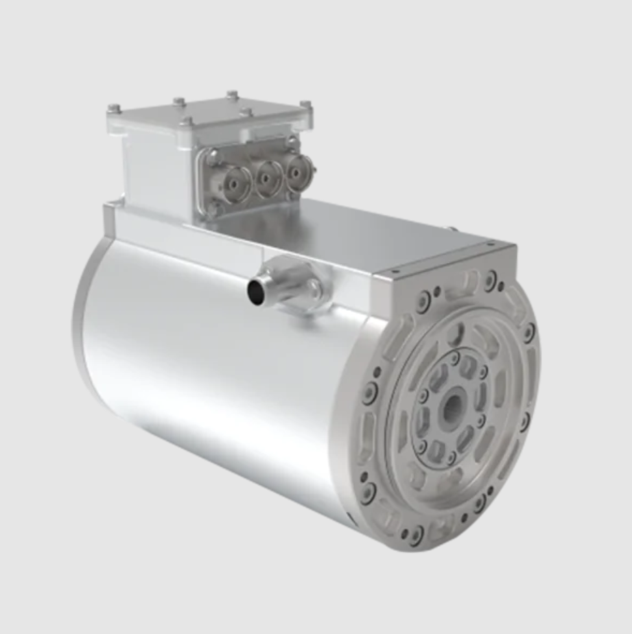
I have focused my work on a flat-wire permanent magnet synchronous motor for new-energy electric vehicle traction. The permanent magnet synchronous motor is attractive because it can combine high power density, high torque density, compact volume, low weight, and high efficiency. For electric vehicle propulsion, these qualities are essential because the machine must deliver strong low-speed torque, maintain wide constant-power speed range, and achieve high efficiency over frequent urban and highway operating points. I use a flat-wire winding in the stator to increase the slot fill factor, reduce the end-winding length, lower the phase resistance, and improve heat dissipation. I also use a V-one type double-layer permanent magnet rotor so that the permanent magnet synchronous motor can exploit reluctance torque and obtain better flux-weakening capability. The target machine is an 8-pole, 48-slot permanent magnet synchronous motor with a rated power of 16 kW, a peak power of 35 kW, a rated torque of 29 N·m, a peak torque of 110 N·m, a rated speed of 5400 r/min, and a peak speed of 9000 r/min.
Motor Topology and Main Parameters
The stator core is laminated, and the stator winding is formed by rectangular flat conductors. The rotor uses a V-one type permanent magnet arrangement with double-layer magnets. This permanent magnet synchronous motor topology allows the rotor to produce both permanent magnet torque and reluctance torque. I set the stator outer diameter to 153 mm, the initial stator inner diameter to 107 mm, the core length to 86 mm, the air-gap length to 0.8 mm, the number of stator slots to 48, the number of poles to 8, and the number of winding layers to 4. The main parameters are summarized in Table 1.
| Parameter | Value | Parameter | Value |
|---|---|---|---|
| Rated power | 16 kW | Stator inner diameter | 107 mm |
| Peak power | 35 kW | Core length | 86 mm |
| Rated torque | 29 N·m | Air-gap length | 0.8 mm |
| Peak torque | 110 N·m | Number of stator slots | 48 |
| Rated speed | 5400 r/min | Number of poles | 8 |
| Peak speed | 9000 r/min | Magnet type | V-one |
| Stator outer diameter | 153 mm | Winding layers | 4 |
Stator-Side Optimization and Design
For a permanent magnet synchronous motor with a fixed stator outer diameter, the stator inner diameter strongly affects the air-gap flux density, the yoke width, the tooth width, the output torque, and the torque ripple. I therefore scanned the stator inner diameter while keeping other parameters constant. The average torque first increases and then decreases as the stator inner diameter increases. The torque ripple first decreases and then increases. When the stator inner diameter is 109 mm, the torque ripple reaches a low value and the maximum torque still satisfies the design requirement. I selected 109 mm as the stator inner diameter for the permanent magnet synchronous motor.
The air-gap length also influences the permanent magnet synchronous motor. A small air-gap length can improve the power factor, but an excessively small air-gap may increase manufacturing difficulty and harmonic distortion. A large air-gap length reduces the direct-axis inductance and can reduce the maximum speed. I scanned the air-gap length and observed that the average torque decreases as the air-gap length increases. The torque ripple first decreases and then increases. When the air-gap length is 0.7 mm, the torque ripple is minimized while the maximum torque remains acceptable. I therefore selected a 0.7 mm air-gap length for the permanent magnet synchronous motor.
Because the stator uses flat-wire winding, I selected a rectangular slot shape to improve slot utilization. The slot height, slot width, slot opening height, and slot opening width were treated as stator-side variables. I defined the average torque and torque ripple as the main responses. The average torque and torque ripple are calculated as follows:
$$ T_{avg} = \frac{1}{T} \int_{0}^{T} T(t)\,dt $$
$$ T_{ripple} = \frac{T_{max} – T_{min}}{T_{avg}} \times 100\% $$
I found that the average torque decreases as the slot height increases, while the torque ripple first decreases slowly and then increases. The average torque and torque ripple both tend to decrease as the slot width increases. I selected a slot height of 12.5 mm and a slot width of 4.15 mm. The flat-wire conductor size was 3.35 mm × 2.5 mm. With an insulation thickness of 0.25 mm, the pure copper slot fill factor was calculated as 74.8%, which is much higher than that of a conventional round-wire permanent magnet synchronous motor.
The slot opening height and slot opening width were also scanned. The average torque decreases as the slot opening height increases. The torque ripple first decreases and then increases. The average torque increases as the slot opening width increases, while the torque ripple first decreases and then increases. I selected a slot opening height of 1 mm and a slot opening width of 1.5 mm. These stator-side choices produce a permanent magnet synchronous motor with a suitable torque level and a lower torque ripple before rotor optimization.
| Stator parameter | Scanned range | Selected value | Main reason |
|---|---|---|---|
| Stator inner diameter | 105–115 mm | 109 mm | Low torque ripple and acceptable maximum torque |
| Air-gap length | 0.5–1.0 mm | 0.7 mm | Minimum torque ripple with acceptable torque |
| Slot height | 12.0–14.0 mm | 12.5 mm | Balanced torque and torque ripple |
| Slot width | 3.5–4.5 mm | 4.15 mm | Reduced torque ripple and suitable flat-wire size |
| Slot opening height | 0.5–2.5 mm | 1.0 mm | Minimum torque ripple |
| Slot opening width | 0.5–2.5 mm | 1.5 mm | Relatively high torque and reduced ripple |
Rotor Auxiliary Slot Optimization
For a permanent magnet synchronous motor, the air-gap flux density should be as sinusoidal as possible. A sinusoidal air-gap flux density reduces the back-electromotive force harmonics, lowers torque ripple, and improves control precision. I introduced non-symmetric auxiliary slots on the rotor surface. The auxiliary slot variables are the auxiliary slot depth $h_{fc}$, the auxiliary slot position $\theta_r$, the inner half-slot angle $\theta_{in}$, and the outer half-slot angle $\theta_{out}$. These variables modify the local magnetic reluctance on the rotor surface and shape the air-gap flux density of the permanent magnet synchronous motor.
I first performed single-variable scans for each auxiliary slot parameter. The auxiliary slot depth has a significant effect on torque ripple and a relatively small effect on average torque. The torque and torque ripple first decrease and then increase as $h_{fc}$ increases. The auxiliary slot position $\theta_r$ causes the torque to first decrease slowly and then increase, while the torque ripple first decreases and then increases. The inner half-slot angle $\theta_{in}$ causes the torque to decrease and the torque ripple to first decrease and then increase. The outer half-slot angle $\theta_{out}$ causes the torque to increase and the torque ripple to first decrease and then increase. These scans confirm that a properly designed auxiliary slot can strongly suppress torque ripple in the permanent magnet synchronous motor.
I then formulated a multi-objective optimization problem. The optimization variables are $h_{fc}$, $\theta_r$, $\theta_{in}$, and $\theta_{out}$. The objectives are to maximize the average torque $T_{avg}$ and to minimize the torque ripple $T_{ripple}$. I used a Box-Behnken design with four factors and three levels. The factor levels are listed in Table 2, and the experimental design and finite-element results are listed in Table 3.
| Level | $h_{fc}$ / mm | $\theta_r$ / deg | $\theta_{in}$ / deg | $\theta_{out}$ / deg |
|---|---|---|---|---|
| −1 | 0.2 | 125 | 17 | 17 |
| 0 | 0.4 | 127 | 20 | 20 |
| 1 | 0.6 | 129 | 23 | 23 |
| Run | $h_{fc}$ | $\theta_r$ | $\theta_{in}$ | $\theta_{out}$ | $T_{avg}$ / (N·m) | $T_{ripple}$ / % |
|---|---|---|---|---|---|---|
| 1 | 0 | −1 | 0 | −1 | 37.82 | 2.252 |
| 2 | 0 | 1 | 0 | −1 | 38.02 | 2.494 |
| 3 | 0 | 0 | −1 | 1 | 38.04 | 2.952 |
| 4 | 1 | 1 | 0 | 0 | 38.12 | 2.850 |
| 5 | −1 | 0 | −1 | 0 | 38.03 | 4.184 |
| 6 | 0 | 1 | 0 | 1 | 38.08 | 3.016 |
| 7 | 0 | 0 | 1 | 1 | 37.94 | 1.897 |
| 8 | 0 | 1 | 1 | 0 | 38.01 | 1.830 |
| 9 | 0 | 0 | 1 | −1 | 37.87 | 1.879 |
| 10 | 1 | −1 | 0 | 0 | 37.83 | 3.567 |
| 11 | 1 | 0 | 1 | 0 | 37.91 | 3.221 |
| 12 | 1 | 0 | 0 | 1 | 38.01 | 2.738 |
| 13 | −1 | 0 | 0 | 1 | 38.02 | 3.710 |
| 14 | 0 | −1 | 0 | 1 | 37.90 | 2.038 |
| 15 | −1 | 0 | 0 | −1 | 37.97 | 3.539 |
| 16 | 1 | 0 | −1 | 0 | 38.05 | 3.335 |
| 17 | 0 | 0 | −1 | −1 | 37.97 | 2.703 |
| 18 | 0 | 1 | −1 | 0 | 38.11 | 3.581 |
| 19 | 1 | 0 | 0 | −1 | 37.92 | 2.904 |
| 20 | −1 | −1 | 0 | 0 | 37.95 | 3.198 |
| 21 | 0 | −1 | −1 | 0 | 37.91 | 2.047 |
| 22 | −1 | 0 | 1 | 0 | 37.97 | 3.188 |
| 23 | 0 | −1 | 1 | 0 | 37.82 | 2.383 |
| 24 | −1 | 1 | 0 | 0 | 38.05 | 4.091 |
| 25 | 0 | −1 | 0 | −1 | 37.82 | 2.252 |
From the finite-element results, I built quadratic response surface models. The regression equations for the average torque and torque ripple of the permanent magnet synchronous motor are:
$$ T_{avg} = 65.42 – 15.485 h_{fc} – 0.4504 \theta_r + 0.011 \theta_{in} + 0.1108 \theta_{out} + 0.8437 h_{fc}^{2} + 0.001875 \theta_r^{2} + 0.000972 \theta_{in}^{2} + 0.11875 h_{fc}\theta_r – 0.03333 h_{fc}\theta_{in} + 0.01667 h_{fc}\theta_{out} – 0.000417 \theta_r\theta_{in} – 0.000833 \theta_r\theta_{out} $$
$$ T_{ripple} = 425 + 100.9 h_{fc} – 8.10 \theta_r + 10.3 \theta_{in} – 3.69 \theta_{out} + 26.26 h_{fc}^{2} + 0.0383 \theta_r^{2} + 0.015 \theta_{in}^{2} – 1.006 h_{fc}\theta_r + 0.368 h_{fc}\theta_{in} – 0.14 h_{fc}\theta_{out} – 0.087 \theta_r\theta_{in} + 0.0307 \theta_r\theta_{out} – 0.0064 \theta_{in}\theta_{out} $$
The fit quality of the response surface models is evaluated by the $P$ value, $R^2$, and adjusted $R^2$. The results are shown in Table 4. The $P$ values are both below 0.0001, and the $R^2$ values are close to 1, so the response surface models can accurately predict the objectives for the permanent magnet synchronous motor.
| Index | $T_{avg}$ | $T_{ripple}$ |
|---|---|---|
| $P$ value | < 0.0001 | < 0.0001 |
| $R^2$ / % | 99.95 | 96.41 |
| Adjusted $R^2$ / % | 99.88 | 91.75 |
I then combined the response surface model with the NSGA-II algorithm. The objective functions are:
$$ f_1(X_i) = \frac{1}{T_{avg}(X_i)} $$
$$ f_2(X_i) = T_{ripple}(X_i) $$
where $X_i$ is the vector of auxiliary slot variables, namely $h_{fc}$, $\theta_r$, $\theta_{in}$, and $\theta_{out}$. The variable ranges are the same as those used in the response surface design. By minimizing both $f_1$ and $f_2$, I simultaneously maximize the average torque and minimize the torque ripple of the permanent magnet synchronous motor. Table 5 lists three representative optimization schemes obtained from the NSGA-II solution set. Table 6 compares the optimization objectives before and after the auxiliary slot optimization.
| Optimization variable | Scheme 1 | Scheme 2 | Scheme 3 |
|---|---|---|---|
| $h_{fc}$ / mm | 0.48 | 0.485 | 0.434 |
| $\theta_r$ / deg | 129 | 129 | 129 |
| $\theta_{in}$ / deg | 23 | 23 | 22.98 |
| $\theta_{out}$ / deg | 20.91 | 23 | 17 |
| Optimization objective | Without auxiliary slot | Scheme 1 | Scheme 2 | Scheme 3 |
|---|---|---|---|---|
| $T_{avg}$ / (N·m) | 38.1 | 38.03 | 38.03 | 37.98 |
| $T_{ripple}$ / % | 5.57 | 1.712 | 1.747 | 1.524 |
Among the three schemes, the auxiliary slot has only a small influence on the average torque. The lowest average torque is 37.98 N·m, which is only 0.33% lower than the value without the auxiliary slot. However, the auxiliary slot strongly reduces the torque ripple. Scheme 3 gives the best torque ripple suppression. Compared with the permanent magnet synchronous motor without auxiliary slots, the torque ripple of Scheme 3 decreases by 72.64%. I therefore selected Scheme 3 as the final rotor design.
Comparative Electromagnetic Performance
The cogging torque is a key issue in the permanent magnet synchronous motor because it is caused by the interaction between the permanent magnet field and the stator slotting when the armature current is zero. A large cogging torque can cause vibration, acoustic noise, reduced control precision, and poor low-speed performance. I compared the cogging torque before and after the rotor auxiliary slot optimization. The peak-to-peak cogging torque without auxiliary slots is 914.788 mN·m. With the optimized auxiliary slots, the peak-to-peak cogging torque decreases to 429.2028 mN·m, a reduction of 53.08%. The optimized peak cogging torque is about 0.22 N·m, which satisfies the design requirement of no more than 0.5 N·m.
| Quantity | Without auxiliary slot | With optimized auxiliary slot | Change |
|---|---|---|---|
| Cogging torque peak-to-peak / mN·m | 914.788 | 429.2028 | −53.08% |
| Peak cogging torque / N·m | — | 0.22 | Requirement ≤ 0.5 |
| Average torque / (N·m) | 38.10 | 37.98 | −0.33% |
| Torque ripple / % | 5.57 | 1.524 | −72.64% |
The no-load air-gap flux density also improves after the auxiliary slot optimization. The fundamental amplitude of the no-load air-gap flux density increases slightly. The local flux-density waveform becomes smoother because the non-symmetric auxiliary slots reshape the rotor surface permeance. The distortion of the air-gap field is reduced, and the permanent magnet synchronous motor obtains a more sinusoidal field distribution. The harmonic content of the no-load air-gap flux density is reduced, which is beneficial for the back-electromotive force waveform and torque quality.
Under rated operation, the average torque of the optimized permanent magnet synchronous motor is 37.98 N·m, and the torque ripple is 1.524%. The torque waveform is much smoother than that of the permanent magnet synchronous motor without auxiliary slots. The average torque remains almost unchanged, while the torque ripple is greatly reduced. This confirms that the response surface model combined with NSGA-II is effective for optimizing rotor auxiliary slots in the permanent magnet synchronous motor.
No-Load Performance Analysis
I analyzed the no-load magnetic field distribution at the maximum speed. The yoke flux density is about 1.3 T, and the tooth flux density is about 1.6 T. Neither the tooth nor the yoke is saturated. The flux density in the magnetic bridge reaches about 2.3 T, which provides good magnetic isolation. The flux density distribution is reasonable for the permanent magnet synchronous motor.
With the stator winding open-circuited and the rotor rotating at 9000 r/min, I obtained the no-load back-electromotive force waveform. The waveform is nearly sinusoidal. The total harmonic distortion of the line-to-line back-electromotive force is calculated as:
$$ THD = \frac{\sqrt{E_2^2 + E_3^2 + E_4^2 + \cdots + E_{13}^2}}{E_1} \times 100\% $$
where $E_1$ is the fundamental amplitude and $E_2$ to $E_{13}$ are the harmonic amplitudes. The calculated THD is 3.04%. This low value indicates that the permanent magnet synchronous motor has a good back-electromotive force waveform and is suitable for field-oriented control.
| No-load quantity | Value |
|---|---|
| Maximum speed | 9000 r/min |
| Back-electromotive force waveform | Nearly sinusoidal |
| THD of back-electromotive force | 3.04% |
| Yoke flux density | About 1.3 T |
| Tooth flux density | About 1.6 T |
| Magnetic bridge flux density | About 2.3 T |
Load Performance and Efficiency Map
Electric vehicle traction motors must operate over multiple conditions, including climbing, peak power, rated efficient operation, and high-speed cruising. I evaluated the permanent magnet synchronous motor at four representative operating points. The first is the climbing point at 1000 r/min. The second is the peak power point at 3800 r/min. The third is the rated power point at 5400 r/min. The fourth is the high-speed point at 9000 r/min. The torque waveforms show that the permanent magnet synchronous motor can meet the maximum torque requirement of 110 N·m at the climbing and peak power points. At the rated point, the average torque is 37.98 N·m and the torque ripple is 1.524%. At the high-speed point, the average torque is 53.66 N·m, which satisfies the high-speed torque requirement. The detailed results are listed in Table 7.
| Operating point | Speed / (r/min) | Average torque / (N·m) | Torque ripple / % |
|---|---|---|---|
| Climbing point | 1000 | 113.86 | 2.46 |
| Peak power point | 3800 | 113.84 | 2.00 |
| Rated power point | 5400 | 37.98 | 1.524 |
| High-speed point | 9000 | 53.66 | 0.97 |
I also calculated the outer characteristic curves of the permanent magnet synchronous motor for both peak power and rated power operation. The peak power curve demonstrates the maximum torque and power capability over the speed range. The rated power curve demonstrates the continuous operating capability. These curves are important for matching the permanent magnet synchronous motor to the vehicle transmission and battery system.
The efficiency of the permanent magnet synchronous motor is calculated from the input power and output power:
$$ \eta = \frac{P_{out}}{P_{in}} \times 100\% $$
where $P_{out}$ is the mechanical output power and $P_{in}$ is the electrical input power. I computed the efficiency over the entire speed-torque plane and obtained the efficiency map. The maximum efficiency of the permanent magnet synchronous motor is 96.63%. The high-efficiency region, defined as efficiency greater than 85%, accounts for 91.36% of the operating area. The highest efficiency occurs near the rated operating condition. The permanent magnet synchronous motor maintains high efficiency over a wide speed range and a wide torque range, which is desirable for electric vehicle traction.
| Performance index | Requirement | Calculated value |
|---|---|---|
| Maximum speed power | ≥ 30 kW | 46.6 kW |
| Rated torque ripple | ≤ 2% | 1.524% |
| Cogging torque | ≤ 0.5 N·m | 0.22 N·m |
| Maximum efficiency | > 95.5% | 96.63% |
| High-efficiency area ratio for efficiency > 85% | ≥ 85% | 91.36% |
The efficiency map confirms that the flat-wire permanent magnet synchronous motor has a high maximum efficiency, a wide high-efficiency region, and a wide speed range. These features are important for reducing battery energy consumption and extending driving range in new-energy electric vehicles. The flat-wire winding contributes to the high efficiency by reducing the direct-current resistance and the copper loss. The V-one type permanent magnet rotor contributes to the wide speed range by providing reluctance torque and improving flux-weakening capability.
Discussion of the Optimization Method
The combined response surface model and NSGA-II method is effective for the multi-objective optimization of the permanent magnet synchronous motor. The response surface model provides a fast surrogate for the finite-element model, and the NSGA-II algorithm searches the Pareto front between average torque and torque ripple. In my design, the auxiliary slot depth, position, inner half-slot angle, and outer half-slot angle are strongly coupled. A single-variable scan is useful for determining the variable ranges, but it cannot fully capture the interactions among the variables. The response surface model captures these interactions through quadratic and cross terms. The NSGA-II algorithm then identifies non-dominated solutions. The finite-element verification shows that the predicted optimum is close to the actual optimum. The final design achieves a large reduction in torque ripple and cogging torque with only a very small sacrifice in average torque.
The role of the auxiliary slot is to modify the local magnetic permeance on the rotor surface. By choosing a non-symmetric shape, the auxiliary slot changes the effective air-gap length distribution in a way that reduces the harmonic components responsible for torque ripple. The auxiliary slot also reduces the cogging torque because it changes the interaction between the permanent magnet field and the stator slot openings. The optimized auxiliary slot does not cause excessive flux leakage or local saturation. The magnetic bridge remains highly saturated, which preserves the required magnetic isolation. The permanent magnet synchronous motor therefore maintains a strong main flux path while gaining improved torque quality.
Key Contributions and Practical Implications
The design process I followed integrates stator-side geometric selection, rotor-side auxiliary slot optimization, and full operating-condition performance evaluation. For a flat-wire permanent magnet synchronous motor, the stator slot shape must be selected together with the flat-wire conductor dimensions. The pure copper slot fill factor of 74.8% is high enough to improve torque density and reduce copper loss. The V-one type permanent magnet rotor provides the permanent magnet synchronous motor with both permanent magnet torque and reluctance torque. The auxiliary slot optimization reduces the torque ripple to 1.524% and the cogging torque to 0.22 N·m. The permanent magnet synchronous motor meets the rated torque ripple requirement of no more than 2% and the cogging torque requirement of no more than 0.5 N·m. The maximum efficiency of 96.63% and the high-efficiency area ratio of 91.36% demonstrate that the flat-wire permanent magnet synchronous motor is suitable for electric vehicle traction.
From a manufacturing perspective, the flat-wire winding requires careful forming and insertion. The rectangular slot and the selected flat-wire dimensions are compatible with a four-layer winding layout. The end winding is shorter than that of a round-wire winding, which helps reduce the axial length and the copper mass. The larger conductor cross-section reduces the phase resistance and improves the thermal performance. The auxiliary slots on the rotor surface are simple to manufacture because they are formed by punching or milling before magnet insertion. The non-symmetric shape can be produced with standard tooling. The optimization result is therefore practical for mass production.
From a control perspective, the low back-electromotive force THD and low torque ripple make the permanent magnet synchronous motor easier to control. Field-oriented control and flux-weakening control can be implemented with lower current harmonics and lower torque pulsation. The wide high-efficiency region reduces the need for aggressive current control at medium and high speeds. The high-speed torque of 53.66 N·m at 9000 r/min indicates that the permanent magnet synchronous motor can provide sufficient power for highway cruising. The peak torque of about 113.86 N·m at low speed indicates that the permanent magnet synchronous motor can satisfy climbing requirements.
Comparison with Conventional Designs
Compared with a conventional round-wire permanent magnet synchronous motor of the same outer diameter, the flat-wire permanent magnet synchronous motor has a higher slot fill factor, lower phase resistance, and better heat dissipation. The higher slot fill factor allows more copper area in the same slot, which increases the torque capability. The lower phase resistance reduces the copper loss and improves the efficiency. The better heat dissipation allows higher continuous current density, which improves the continuous torque capability. The V-one type permanent magnet rotor also provides a higher saliency ratio than a surface-mounted permanent magnet synchronous motor, which increases the reluctance torque and improves the flux-weakening capability.
| Feature | Round-wire permanent magnet synchronous motor | Flat-wire permanent magnet synchronous motor |
|---|---|---|
| Slot fill factor | Typically lower | 74.8% pure copper |
| End winding | Longer | Shorter |
| Phase resistance | Higher | Lower |
| Copper loss | Higher | Lower |
| Heat dissipation | Moderate | Better |
| Torque density | Lower | Higher |
| Rotor topology | Often surface-mounted or single-layer | V-one double-layer |
| Reluctance torque | Limited | Enhanced |
| Flux-weakening capability | Moderate | Improved |
Further Observations on Torque Quality
The torque ripple of the permanent magnet synchronous motor comes from several sources, including cogging torque, back-electromotive force harmonics, and current harmonics. The auxiliary slots primarily target the cogging torque and the air-gap flux density harmonics. By reducing the cogging torque peak-to-peak value from 914.788 mN·m to 429.2028 mN·m, the low-speed torque quality is substantially improved. The torque ripple at rated operation is reduced from 5.57% to 1.524%. This reduction is important because torque ripple can excite mechanical resonances in the drivetrain and can cause unacceptable noise and vibration in the vehicle. The optimized permanent magnet synchronous motor therefore provides a smoother driving experience.
The average torque is nearly unchanged because the auxiliary slots are placed in regions where they do not significantly reduce the main flux linkage. The small reduction of 0.33% is acceptable because the improvement in torque quality is much larger. The multi-objective optimization ensures that the design is not overly biased toward either objective. The NSGA-II solution set provides several candidate designs, and the final selection can be made based on additional criteria such as manufacturability, mechanical strength, or thermal performance.
Thermal and Efficiency Considerations
The flat-wire winding is advantageous for thermal management. The rectangular conductors have a large contact area with the slot insulation and the stator core. The voids between the flat conductors can be filled with impregnating varnish or thermally conductive material. The heat generated by copper loss can therefore be transferred to the stator core and the housing more effectively. The lower phase resistance also reduces the copper loss for a given current. These effects contribute to the high efficiency of 96.63% and the wide high-efficiency region of 91.36%. The permanent magnet synchronous motor can therefore operate at high torque density for longer periods without exceeding thermal limits.
The efficiency map shows that the high-efficiency region covers both low-speed high-torque operation and high-speed medium-torque operation. This is important for electric vehicles because the operating point moves frequently between urban driving and highway driving. A wide high-efficiency region reduces the average energy consumption over a driving cycle. The permanent magnet synchronous motor is therefore well suited to new-energy electric vehicles.
Design Guidelines Derived from This Work
Several design guidelines emerge from my analysis of the flat-wire permanent magnet synchronous motor. First, the stator inner diameter and air-gap length should be selected together because they affect both torque and torque ripple. Second, the stator slot dimensions should be chosen to accommodate the flat-wire conductor while maintaining a high slot fill factor and a low torque ripple. Third, the rotor auxiliary slots should be optimized using a multi-objective method because the auxiliary slot parameters interact with each other. Fourth, the response surface model should be validated by finite-element analysis before it is used in the optimization. Fifth, the final design should be evaluated over the entire operating range, not only at the rated point, because electric vehicle traction motors operate over wide speed and torque ranges.
| Design stage | Key variables | Main objective | Selected result |
|---|---|---|---|
| Stator inner diameter | $D_{si}$ | Balance torque and ripple | 109 mm |
| Air-gap length | $g$ | Minimize ripple | 0.7 mm |
| Slot height | $h_1$ | Balance torque and ripple | 12.5 mm |
| Slot width | $w_1$ | Reduce ripple | 4.15 mm |
| Slot opening height | $h_2$ | Minimize ripple | 1.0 mm |
| Slot opening width | $w_2$ | Increase torque | 1.5 mm |
| Auxiliary slot depth | $h_{fc}$ | Reduce ripple | 0.434 mm |
| Auxiliary slot position | $\theta_r$ | Reduce ripple | 129 deg |
| Inner half-slot angle | $\theta_{in}$ | Reduce ripple | 22.98 deg |
| Outer half-slot angle | $\theta_{out}$ | Reduce ripple | 17 deg |
Conclusion
I designed and analyzed a flat-wire permanent magnet synchronous motor for new-energy electric vehicles. The permanent magnet synchronous motor uses an 8-pole, 48-slot stator with flat-wire winding and a V-one type double-layer permanent magnet rotor. The flat-wire winding achieves a pure copper slot fill factor of 74.8%, which improves torque density and reduces copper loss. The stator inner diameter, air-gap length, slot height, slot width, slot opening height, and slot opening width were selected to obtain a suitable torque level and a low torque ripple. The rotor surface auxiliary slots were optimized by a response surface model combined with the NSGA-II algorithm. The optimized auxiliary slot reduces the torque ripple by 72.64% and the cogging torque by 53.08%, while the average torque decreases by only 0.33%. The optimized permanent magnet synchronous motor has a rated torque ripple of 1.524% and a cogging torque of 0.22 N·m, both of which meet the design requirements. The no-load back-electromotive force has a nearly sinusoidal waveform with a THD of 3.04%. The rated torque is 37.98 N·m, the high-speed torque at 9000 r/min is 53.66 N·m, and the peak torque exceeds 110 N·m at low speed. The efficiency map shows a maximum efficiency of 96.63% and a high-efficiency area ratio of 91.36% for efficiency greater than 85%. These results demonstrate that the flat-wire permanent magnet synchronous motor with optimized rotor auxiliary slots is a strong candidate for electric vehicle traction. The permanent magnet synchronous motor combines high torque density, low torque ripple, low cogging torque, wide speed range, and high efficiency. The design and optimization method can be extended to other flat-wire permanent magnet synchronous motor topologies for new-energy electric vehicles.