
We have been working on thermal management of electric drive systems for battery electric vehicles, and our attention is repeatedly drawn to the permanent magnet synchronous motor because it sits at the center of power density, efficiency, and durability. The permanent magnet synchronous motor offers high torque density and high efficiency, but its performance is strongly coupled to temperature. When the permanent magnet synchronous motor operates at high power density, copper loss in the stator winding, iron loss in the stator core, and eddy-current loss in the permanent magnets generate heat that cannot be removed quickly enough by conventional single-mode cooling. We have observed that excessive temperature in a permanent magnet synchronous motor can cause irreversible demagnetization of the permanent magnets, accelerated aging of winding insulation, and degradation of the lubricant in the reducer. Therefore, we propose a multimodal coupled active cooling system and a control method that treats the permanent magnet synchronous motor as a distributed heat source with distinct thermal paths rather than as a single lumped component.
Our design philosophy is simple to state but difficult to execute: partition the thermal problem, coordinate the cooling modes, and predict the thermal trajectory before it becomes a limitation. We combine a three-layer composite stator cooling structure, a dual-path rotor cooling scheme, and a long short-term memory neural network controller that performs feedforward temperature prediction and multi-objective flow distribution. The permanent magnet synchronous motor is not cooled by one mechanism alone; instead, the stator and rotor receive different cooling treatments according to their heat generation characteristics and spatial constraints. We use liquid cooling as the continuous heat removal backbone, oil cooling for direct hot-spot contact, phase change material for transient peak shaving, and intelligent control for dynamic resource allocation. The result is a thermal management system that reduces temperature rise, lowers parasitic power consumption, and increases power density.
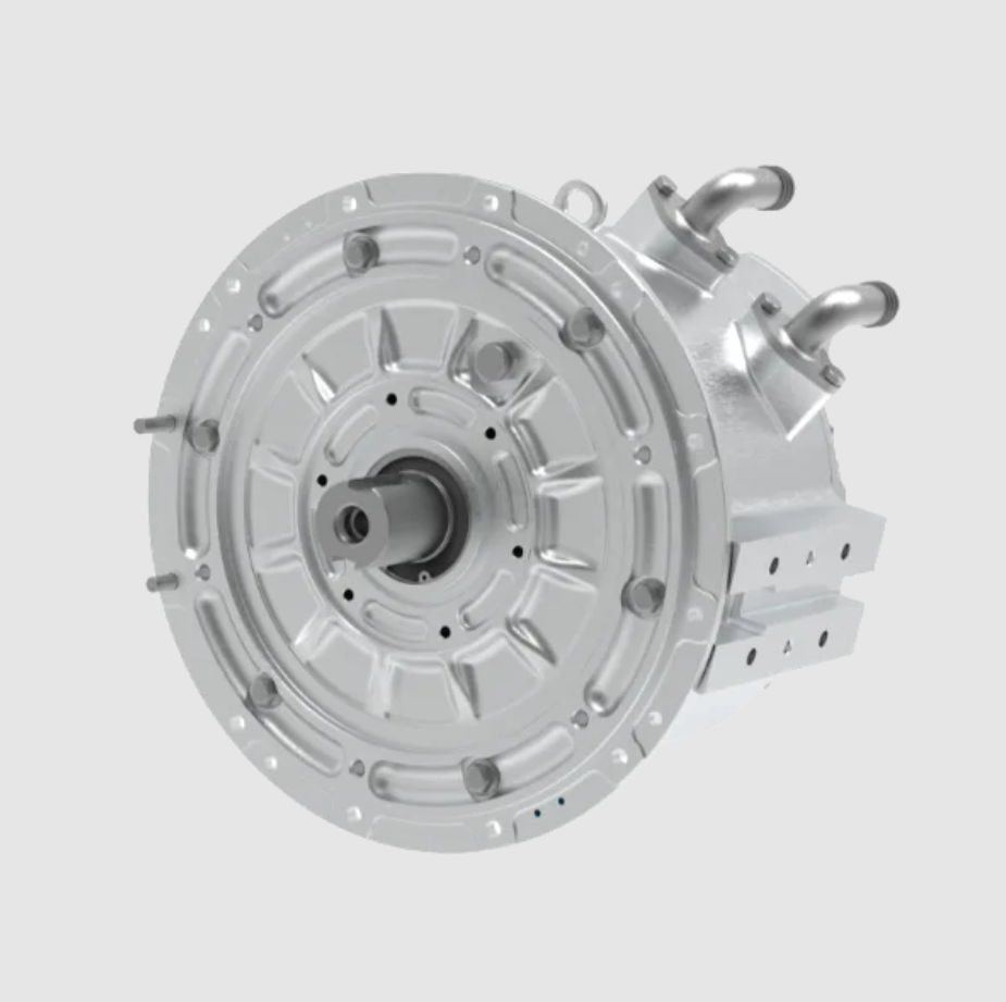
In the following sections, we describe the heat sources in the electric drive system, explain why multimodal coupling is necessary, present the stator and rotor cooling structures, formulate the intelligent control strategy, and report experimental results. We use tables and equations to make the design and the control logic reproducible. We also insert a representative visual of the permanent magnet synchronous motor and its cooling architecture in the appropriate place. Our goal is to provide a technical pathway that improves thermal management efficiency, extends driving range, and reduces overall vehicle cost.
Heat sources and thermal requirements. The electric drive system contains three major heat sources: the permanent magnet synchronous motor, the motor controller, and the reducer. Within the permanent magnet synchronous motor, the dominant losses are stator copper loss and stator iron loss, which together account for the majority of the heat generated. The permanent magnets are the most temperature-sensitive part of the permanent magnet synchronous motor because their magnetic properties degrade irreversibly above a threshold temperature. The motor controller, especially the insulated gate bipolar transistor module, contributes switching and conduction losses, and its junction temperature must remain below a safe limit. The reducer contributes gear meshing friction and bearing losses, and its lubricant must remain below its degradation temperature. We summarize these heat sources in Table 1.
| Component | Main heat source | Heat generation share | Temperature-sensitive point and failure risk |
|---|---|---|---|
| Permanent magnet synchronous motor | Stator copper loss (I²R), stator iron eddy current loss | 60%–70% | Permanent magnet above 150 °C: demagnetization; winding insulation aging |
| Motor controller | IGBT/MOSFET switching and conduction loss | 20%–30% | Junction temperature above 175 °C: breakdown |
| Reducer | Gear meshing friction, bearing loss | 10%–15% | Lubricant above 140 °C: failure |
We quantify the copper loss in the permanent magnet synchronous motor as
$$P_{cu} = I^2 R$$
where I is the phase current and R is the phase resistance. The iron loss is commonly decomposed into hysteresis loss and eddy current loss:
$$P_{fe} = k_h f B_m^n + k_e f^2 B_m^2$$
where f is the electrical frequency, B_m is the peak magnetic flux density, and k_h, k_e, and n are material-dependent coefficients. The permanent magnet eddy current loss is
$$P_{pm} = \int_V \frac{J^2}{\sigma} \, dV$$
where J is the induced current density and σ is the electrical conductivity of the permanent magnet. These losses are not uniformly distributed. In the permanent magnet synchronous motor, the stator winding end regions and the stator teeth are often the hottest spots, while the rotor magnets are difficult to cool because heat must cross the air gap or travel along the shaft. This spatial non-uniformity is the reason why a single cooling mode is insufficient.
Why multimodal coupling is necessary. We compared the mainstream cooling methods and summarized their roles in Table 2. Liquid cooling provides high heat transfer efficiency and is cost-effective, but it cannot directly cool internal hot spots. Oil cooling can directly contact heat-generating components and produce significant temperature reduction, but it requires complex sealing and adds mass and cost. Phase change cooling absorbs a large amount of latent heat during phase transition and can buffer transient thermal shocks without parasitic power, but its heat capacity is limited and it must release heat periodically. Air cooling is simple and low cost, but its heat transfer efficiency is low and it is only suitable for low-power scenarios. Therefore, we use a multimodal coupled approach in which each mode compensates for the limitations of the others in space and time.
| Cooling mode | Principle | Advantages | Limitations | Role in the multimodal system |
|---|---|---|---|---|
| Liquid cooling | Coolant flows through channels and removes heat | High heat transfer efficiency, controllable cost | Cannot directly cool internal hot spots | Baseline continuous heat removal |
| Oil cooling | Oil directly contacts heat-generating parts | Direct hot-spot cooling, significant temperature drop | Complex sealing, additional mass and cost | Targets rotor, windings, and internal critical regions |
| Phase change cooling | Material absorbs latent heat during phase transition | No parasitic power, resists transient thermal shock | Limited heat capacity, periodic heat release required | Thermal buffer and peak temperature shaving |
| Air cooling | Forced air convection | Simple structure, low cost | Low heat transfer efficiency, only for low power | Auxiliary cooling or specific scenarios |
We base our design on the principle of “partitioned management and coordinated control.” For the permanent magnet synchronous motor, we design the optimal cooling path for the stator and the rotor separately and then manage them through a unified intelligent controller. The stator cooling structure uses a three-layer composite shell that combines a nanoporous ceramic thermal conductive layer, a graphene-based phase change material layer, and a microchannel liquid cooling plate. The rotor cooling structure uses a dual-path scheme with axial oil channels and radial spray. The controller uses a long short-term memory network to predict the thermal state and allocate flow dynamically. In this way, the permanent magnet synchronous motor receives cooling that is matched to its instantaneous loss distribution.
Stator three-layer composite cooling structure. The stator heat is concentrated in the windings and the iron core, and the conduction path to the housing is relatively long. To solve this problem, we designed a three-layer composite cooling shell. The inner layer is a nanoporous ceramic thermal conductive layer made of a high-porosity SiC or AlN ceramic skeleton with a porosity of approximately 70%. The anisotropic thermal conductivity of this layer rapidly conducts heat from the stator core and windings in the radial direction to the middle layer. The AlN ceramic skeleton has a high melting point, and the nanopores suppress sintering shrinkage at high temperature, so the pore structure remains stable and the performance does not degrade. We compared high thermal conductivity skeleton materials in Table 3.
| Material system | Solid-phase thermal conductivity (dense state) / (W/m·K) | Characteristics and application considerations |
|---|---|---|
| SiC | 120–270 | Good high-temperature stability, moderate cost |
| AlN | 200–320 | Extremely high thermal conductivity, requires oxidation protection |
| ZrB₂/SiC composite ceramic | 60–100 | Ultra-high temperature stability, suitable for extreme environments |
The middle layer is a graphene-based phase change material. Graphene sheets with a thickness of 0.335 nm form a three-dimensional thermal conductive network inside the phase change material, allowing heat to spread rapidly. The nanoconfinement effect, in which graphene encapsulates paraffin molecules, reduces the voids between paraffin molecules, suppresses molecular mobility, reduces phase change leakage, and improves particle structure stability. This layer receives the heat conducted from the inner layer and absorbs a large amount of latent heat near the phase change point of 65 °C, with a latent heat value of at least 250 kJ/kg. It acts as a thermal buffer, smooths temperature fluctuations, and makes temperature measurement more accurate. Table 4 compares the performance of conventional paraffin phase change material and graphene-based phase change material. The addition of graphene significantly improves the comprehensive performance.
| Characteristic | Conventional paraffin PCM | Graphene-based PCM | Improvement |
|---|---|---|---|
| Thermal conductivity / [W/(m·K)] | 0.2–0.3 | 5–15 | 20–50 times higher |
| Latent heat / (kJ/kg) | 180–220 | ≥250 | 15%–30% higher |
| Thermal response speed | Slow | Fast (shortened by 40%) | Better response to transient thermal shock |
| Cycle stability | Degradation >20% after 500 cycles | Degradation <5% after 1000 cycles | Significantly extended life |
The outer layer is a double-spiral microchannel liquid cooling plate with a channel width of only 0.5 mm. The double-spiral structure ensures that the coolant flows over the outer surface of the stator in a large area and uniformly. As the coolant flows along the spiral path from one side to the other, it contacts a large portion of the motor, increasing the heat exchange area and allowing heat to be transferred to the coolant quickly. This layer efficiently removes the heat released by the phase change material and the heat conducted directly through the inner layers. We use a coolant that consists of a conventional water-glycol solution (50:50) with 1.5 wt% boron nitride nanosheets dispersed in it. The high insulation and high thermal conductivity of boron nitride nanosheets improve the overall thermal conductivity of the coolant by approximately 35%. The three-layer composite cooling structure of the stator shell is shown in the figure below.
We can describe the heat conduction through the three-layer stator shell using the one-dimensional thermal resistance network. The heat flux through the layers is
$$q = \frac{T_{stator} – T_{coolant}}{R_{inner} + R_{pcm} + R_{outer}}$$
where the thermal resistance of each layer is
$$R_i = \frac{L_i}{k_i A_i}$$
with L_i the thickness, k_i the effective thermal conductivity, and A_i the heat transfer area. The phase change material adds a transient thermal capacitance effect:
$$Q_{pcm} = m_{pcm} L_f + m_{pcm} c_{p,pcm} \Delta T$$
where m_{pcm} is the mass of the phase change material, L_f is the latent heat of fusion, c_{p,pcm} is the specific heat, and ΔT is the sensible temperature change. The liquid cooling plate removes heat by convection:
$$Q_{liquid} = \dot{m}_{coolant} c_{p,coolant} (T_{out} – T_{in})$$
where \dot{m}_{coolant} is the coolant mass flow rate, c_{p,coolant} is the specific heat of the coolant, and T_{out} and T_{in} are the outlet and inlet temperatures. By combining these equations, we can size the three layers so that the stator temperature remains below the insulation limit even during peak torque operation.
Rotor dual-path cooling structure. The rotor of the permanent magnet synchronous motor is difficult to cool because it rotates at high speed and its heat must cross the air gap or travel along the shaft. We designed a dual-path scheme that combines forced convection and evaporative heat transfer. The first path is an axial oil channel. We embed a minimal quantity lubrication nozzle in the motor housing that precisely controls the oil flow rate from 0.2 to 1.5 mL/s. The oil is injected directly onto the rotor, which greatly enhances cooling and also improves bearing lubrication. The second path is radial spray. We laser-etch micropores with a diameter of 50 μm on the rotor. The centrifugal force of the rotor atomizes the oil and drives it to the rotor surface, increasing the heat exchange area and achieving efficient heat dissipation without adding rotor drag.
The oil flow in the system is a closed loop. The oil pump draws oil from the oil tank, passes it through a filter, and pressurizes it to a rotary distributor. The pressurized oil enters the central oil channel of the rotor hollow shaft and the housing oil channel through a three-way valve, and then reaches the nozzles inside the shaft and the housing minimal quantity lubrication nozzle. The nozzle inside the shaft sprays oil into the hollow shaft, and the oil is discharged through the micropores under centrifugal force to remove heat. The axial minimal quantity lubrication nozzle sprays oil onto the rotor surface. After absorbing heat, part of the oil evaporates, and the rest is thrown to the inner wall of the rotor by centrifugal force. The oil that completes heat exchange, including oil mist and droplets, finally collects at the bottom of the housing and returns to the oil tank through a pipeline. In the oil tank or in an external loop, the used oil exchanges heat with the vehicle cooling system through an oil cooler and is cooled for reuse.
We can estimate the centrifugal force driving the radial spray as
$$F_c = m_{oil} \omega^2 r$$
where m_{oil} is the mass of an oil droplet, ω is the angular velocity of the rotor, and r is the radial position. The atomization quality depends on the Weber number:
$$We = \frac{\rho_{oil} v^2 d}{\sigma_{oil}}$$
where ρ_{oil} is the oil density, v is the relative velocity, d is the droplet diameter, and σ_{oil} is the surface tension. The heat transfer from the rotor surface to the oil spray can be approximated by
$$Q_{rotor} = h_{spray} A_{rotor} (T_{rotor} – T_{oil}) + \dot{m}_{evap} h_{fg}$$
where h_{spray} is the spray heat transfer coefficient, A_{rotor} is the wetted area, T_{rotor} is the rotor temperature, T_{oil} is the oil temperature, \dot{m}_{evap} is the evaporation mass flow rate, and h_{fg} is the latent heat of vaporization. The axial oil channel adds a convective term:
$$Q_{axial} = h_{axial} A_{channel} (T_{rotor} – T_{oil})$$
By controlling the split between axial flow and radial spray, we can optimize the rotor cooling for different operating points. Table 5 summarizes the key parameters of the rotor dual-path cooling design.
| Parameter | Value or range | Function |
|---|---|---|
| Axial oil flow rate | 0.2–1.5 mL/s | Direct cooling of rotor and bearing lubrication |
| Radial micropore diameter | 50 μm | Oil atomization and surface wetting |
| Oil pump PWM frequency | 1–10 kHz | Precise pressure and flow control |
| Proportional valve opening | 0%–100% | Flow split between axial and radial paths |
| Phase change point of stator PCM | 65 °C | Thermal buffering near optimal magnet temperature |
System work flow. The entire cooling system operates through the cooperation of sensors, controllers, and actuators. The controller is integrated into the motor controller. For the stator and oil cooler cooling, the stator temperature sensor collects the stator temperature in real time and uploads it to the controller. The controller provides the cooling demand to the vehicle controller. The vehicle controller controls the water pump to provide the flow expected by the controller. The controller controls the three-way valve to distribute the flow to the stator microchannel and the oil cooler. For the rotor cooling, the rotor temperature sensor collects the rotor temperature in real time and uploads it to the controller. The controller calculates and controls the oil pump to circulate the oil. Through the three-way valve, the oil is distributed to the axial oil channel and the radial spray channel. This closed-loop architecture allows the permanent magnet synchronous motor to maintain its temperature within the desired band under both steady and transient conditions.
Intelligent thermal management and cooperative control strategy. The overall architecture of our thermal management system forms a complete perception-prediction-decision-execution closed loop. The system uses multi-source sensors, including temperature, current, speed, and vehicle speed, to sense the thermal state of the permanent magnet synchronous motor and the operating state of the vehicle in real time. The core controller uses a long short-term memory network temperature prediction model as the feedforward brain and a multi-objective optimizer as the decision center. It cooperatively adjusts the coolant pump, oil pump, valves, and other actuators to achieve precise, efficient, and smooth control of the motor temperature. Accurate thermal state prediction based on the long short-term memory temperature prediction model is the prerequisite for predictive control. We selected the long short-term memory network because it captures the strong nonlinearity and time dependence of the thermal dynamics of the permanent magnet synchronous motor.
Data preparation and feature engineering. The data source combines vehicle controller area network bus data and custom sensor data with a high sampling rate of at least 10 Hz. The key features include motor phase currents I_d and I_q, rotational speed n, direct current bus voltage U_dc, historical temperature sequences for the stator winding T_s, rotor T_r, and coolant inlet T_coolant, as well as vehicle signals such as vehicle speed v and accelerator pedal opening A_cc. We use a sliding time window to construct supervised learning samples. We normalize the raw data as
$$x_{norm} = \frac{x – x_{min}}{x_{max} – x_{min}}$$
We also use an isolation forest algorithm to detect and remove outliers to ensure data quality. The input sequence length is L, for example 60 time steps corresponding to 1 minute of historical data. The output is the predicted temperature for the next P time steps, for example 10 steps corresponding to the next 10 seconds.
Long short-term memory network model construction. We designed a two-layer stacked long short-term memory network to balance model expressiveness and computational efficiency. The input layer receives a feature sequence of length L. The first long short-term memory layer has 64 neurons and returns the full sequence to capture high-level temporal patterns. A dropout layer with a dropout rate of 0.2 prevents overfitting. The second long short-term memory layer has 32 neurons and returns only the output of the last time step to summarize the information. The fully connected output layer outputs the predicted temperature for the next P time steps. The internal gate equations of the long short-term memory cell are
$$f_t = \sigma(W_f [h_{t-1}, x_t] + b_f)$$
$$i_t = \sigma(W_i [h_{t-1}, x_t] + b_i)$$
$$\tilde{C}_t = \tanh(W_C [h_{t-1}, x_t] + b_C)$$
$$C_t = f_t C_{t-1} + i_t \tilde{C}_t$$
$$o_t = \sigma(W_o [h_{t-1}, x_t] + b_o)$$
$$h_t = o_t \tanh(C_t)$$
where f_t is the forget gate, i_t is the input gate, o_t is the output gate, C_t is the cell state, h_t is the hidden state, W and b are weight matrices and bias vectors, and σ is the sigmoid function. We train the network using a historical driving dataset covering urban, suburban, and highway conditions, split into training, validation, and test sets at 70%, 15%, and 15%. We use the Adam optimizer and the root mean square error as the loss function:
$$RMSE = \sqrt{\frac{1}{N} \sum_{i=1}^{N} (T_{pred,i} – T_{true,i})^2}$$
On the test set, the mean absolute error of the model for the hot-spot temperature prediction within the next 10 seconds is stable within ±1.5 °C, which meets the control accuracy requirement. We lightweight the trained model and integrate it into the vehicle domain controller for millisecond-level online real-time prediction.
Prediction-based multi-parameter cooperative control strategy. The core task of the controller is to convert the temperature prediction values into optimal control commands for multiple cooling actuators. We use a hierarchical cooperative control method. The upper layer is a multi-objective optimization decision maker. This layer uses the predicted temperature trajectory from the long short-term memory network, the motor efficiency map, and the cooling accessory power consumption model to solve a rolling horizon optimization problem within one control cycle. The optimization objective, or cost function J, is
$$J = \sum_{k=1}^{N} \left[ w_1 (T_{pred,k} – T_{target})^2 + w_2 P_{pump,k} + w_3 P_{oil\_pump,k} \right]$$
where T_target is the target temperature of the optimal efficiency region, for example 80 °C, P_pump and P_oil_pump are the predicted power consumption of the water pump and oil pump, and w_1, w_2, and w_3 are weight coefficients that can be dynamically adjusted according to the driving mode. For example, in sport mode, performance is weighted more heavily, while in eco mode, energy efficiency is weighted more heavily. The optimizer outputs the expected total heat removal Q_rep for the next period and the optimal distribution ratio K between stator cooling and rotor cooling, where
$$K = \frac{Q_{stator}}{Q_{total}}$$
The lower layer is a multi-actuator cooperative controller. This layer parses the total heat removal and distribution ratio from the upper layer into specific commands for each actuator and fine-tunes them through feedback. For the stator cooling loop, the required heat removal is
$$Q_{stator,rep} = K Q_{rep}$$
Combined with the coolant temperature difference, the required flow rate F_coolant is calculated. By querying the flow-power characteristic curve of the electronically controlled water pump, we obtain the optimal speed command, achieving three-stage control at 2, 4, and 6 L/min or finer stepless speed regulation. For the rotor cooling loop, the required heat removal is
$$Q_{rotor,rep} = (1 – K) Q_{rep}$$
Combined with the predicted rotor temperature, we decide whether to use axial oil channel cooling as the main mode or radial spray cooling as the main mode. By adjusting the pulse width modulation frequency of the electronic oil pump from 1 to 10 kHz and the proportional valve opening, we precisely control the injection pressure and flow rate from 0.2 to 1.5 mL/s. For phase change material state coordination, we monitor the phase change state, whether solid, phase transition, or liquid. When a large power impact is predicted, we can slightly reduce the liquid cooling intensity in advance so that the phase change material absorbs part of the peak heat, protecting the permanent magnet synchronous motor and reducing the instantaneous high power consumption of the water pump.
Failure protection and safety redundancy. When the model prediction error continuously exceeds a threshold, the system automatically switches to a robust backup controller based on reinforcement learning rules. For hardware failures, critical loops such as the main water pump and main oil pump use dual redundancy. When a fault is detected, the system can switch to the backup loop within milliseconds and adjust the cooling strategy to a safe but performance-limited mode, meeting the automotive safety integrity level C functional safety requirement. These layers of protection ensure that the permanent magnet synchronous motor remains safe even when the intelligent prediction or a cooling actuator fails.
Experimental results and performance analysis. To verify the effectiveness of our scheme, we conducted comparative tests. The test bench conditions were an ambient temperature of 55 ± 2 °C, humidity of 45%–75% RH, air pressure of 86–106 kPa, coolant temperature of 65 ± 2 °C, coolant flow rate of 8 L/min, and operating mode 3.2. We recorded the temperature rise curves of the conventional thermal management system and our proposed system. We also tested the output characteristics of the electric drive system at minimum, rated, and maximum voltage. At the peak torque and peak power points, we ran the system for 30 seconds. The initial motor temperature was 80–85 °C, and the cooling system started official testing after 5 minutes of operation. The bench was a 250 kW dynamometer. We recorded the motor temperature and the output power simultaneously. We compared the motor efficiency maps of the conventional thermal management system and our proposed system.
The results show that our scheme performs excellently in cooling. Under the same torque and speed conditions, the maximum temperature of our scheme is about 18 °C lower than that of the conventional system. Moreover, precise control greatly reduces the system’s own power consumption. The motor efficiency region with efficiency greater than or equal to 80% is greatly increased under the same voltage. Table 6 summarizes the key performance comparison.
| Performance metric | Conventional liquid cooling system | Our multimodal coupled system | Improvement |
|---|---|---|---|
| Stator temperature rise | Baseline | 41.7% lower | Significant reduction |
| Rotor temperature rise | Baseline | 43.5% lower | Significant reduction |
| System power consumption | Baseline | 50.6% lower | Reduced parasitic loss |
| Power density | Baseline | 6.8 kW/kg | Increased by more than 60% |
We also evaluated the efficiency improvement. The motor efficiency map shows that the high-efficiency region expands significantly with our thermal management system. We can express the efficiency as
$$\eta = \frac{P_{out}}{P_{in}} = \frac{P_{out}}{P_{out} + P_{loss}}$$
where P_out is the mechanical output power and P_loss is the total loss, including copper loss, iron loss, permanent magnet eddy current loss, and mechanical loss. By reducing the temperature of the permanent magnet synchronous motor, we reduce the winding resistance and the magnet eddy current loss, which directly improves efficiency. The reduction in cooling system power consumption further improves the overall system efficiency. The combined effect is a longer driving range and lower vehicle cost.
We further analyzed the contribution of each cooling mode. The stator three-layer structure is responsible for a large portion of the stator temperature reduction. The phase change material layer absorbs transient heat peaks and reduces the peak temperature by several degrees. The microchannel liquid cooling plate removes the steady-state heat. The rotor dual-path cooling reduces the rotor temperature rise by more than 40% compared with conventional rotor cooling. The axial oil channel provides continuous cooling and lubrication, while the radial spray provides additional cooling during high-speed operation. The intelligent controller adjusts the flow distribution in real time, so the system does not waste pumping power when the thermal load is low.
We also examined the response to transient events. When the permanent magnet synchronous motor undergoes a sudden torque increase, the loss increases rapidly. The long short-term memory network predicts the temperature trajectory, and the multi-objective optimizer increases the coolant and oil flow before the temperature reaches the limit. The phase change material provides a thermal buffer during the delay between prediction and actuator response. This coordinated action prevents overshoot and reduces thermal cycling, which extends the life of the permanent magnet synchronous motor.
Discussion. The experimental results confirm that multimodal coupling is an effective approach for the thermal management of the permanent magnet synchronous motor. The combination of structural innovation and intelligent control achieves a temperature reduction that cannot be obtained by a single cooling mode. The use of a nanoporous ceramic thermal conductive layer improves radial heat conduction. The graphene-based phase change material provides a passive thermal buffer with high latent heat and stable cycling. The double-spiral microchannel liquid cooling plate provides uniform and efficient heat removal. The rotor dual-path cooling addresses the difficult-to-cool rotor region. The long short-term memory network provides accurate temperature prediction, and the multi-objective optimizer balances cooling performance and power consumption. The result is a permanent magnet synchronous motor that operates at a lower temperature, with higher power density and lower system power consumption.
We note that the integration of these technologies requires careful design of the coolant and oil circuits. The sealing of the oil circuit must be robust to avoid leakage and contamination. The compatibility of the graphene-based phase change material with the surrounding materials must be ensured over long-term cycling. The long short-term memory model must be trained on a representative dataset and validated under different driving conditions. The failure protection and safety redundancy must be designed to meet functional safety requirements. These are engineering challenges that we continue to address.
Conclusion and future work. We designed and verified a multimodal coupled active cooling system and control method for the permanent magnet synchronous motor. Through the structural innovation of stator layered cooling and rotor dual-path cooling, as well as intelligent control based on long short-term memory, we significantly improved the heat dissipation efficiency and operational reliability of the permanent magnet synchronous motor. Experiments show that the system effectively reduces the temperature rise of key components by about 40%, reduces system power consumption by about 50%, and increases power density by more than 60%. This research provides an effective technical pathway for improving the thermal management efficiency of electric drive systems in battery electric vehicles, extending driving range, and reducing overall vehicle cost.
Future work will focus on three areas. First, system integration optimization: we will further optimize the flow channel and structural design to improve space utilization and reduce cost and weight. Second, material and working fluid development: we will explore higher-performance phase change materials and nano-additives to continuously improve thermal management efficiency. Third, advanced control algorithms: we will study more lightweight edge artificial intelligence algorithms and explore deep coordination with vehicle energy management to achieve global energy efficiency optimization. We believe that the permanent magnet synchronous motor will continue to be the core of electric drive systems, and multimodal active cooling with intelligent control will be essential for unlocking its full potential.
In summary, our work demonstrates that a permanent magnet synchronous motor can be cooled more effectively when multiple cooling modes are coupled and controlled by a predictive algorithm. The permanent magnet synchronous motor benefits from lower stator and rotor temperatures, lower system power consumption, and higher power density. The permanent magnet synchronous motor thermal management problem is complex, but our results show that a well-designed multimodal system can meet the challenge. We will continue to refine the design and control strategy to bring this technology closer to widespread production application.