
In this review I examine how the permanent magnet synchronous motor has moved from being a niche high-performance actuator to the default prime mover of the modern paper machine. The argument I develop is straightforward: the permanent magnet synchronous motor is not merely a more efficient replacement for the induction machine, it is the enabling technology for a fundamentally different architecture of paper machine drives, one built on direct drive, wide-speed-range operation, tight multi-axis synchronization, and data-driven plant-level optimization. I organize the discussion around four questions: what makes the permanent magnet synchronous motor intrinsically superior, how its control strategies map onto specific papermaking duties, how those strategies are assembled into a complete application system, and how industrial connectivity and digital twins extend the value of the permanent magnet synchronous motor from the shaft to the entire mill.
1. Context: Why Drive Efficiency Became a Strategic Issue
The global electricity system is dominated by motors. Roughly forty-five percent of all electrical energy produced is consumed by electric motor systems, and in continuous-process industries such as pulp and paper the share is higher still. Because the paper industry operates continuously, at high load factors, and with hundreds of driven points along a single production line, small per-unit efficiency gains translate into very large absolute energy savings. A single modern paper machine commonly carries more than two hundred motors distributed across stock preparation, forming, pressing, drying, sizing, calendering, and rewinding.
The traditional induction motor, despite a century of refinement, carries an inherent efficiency penalty. Its rotor field must be induced, which means rotor copper loss is unavoidable at every operating point, and its efficiency collapses quickly as load departs from rated conditions. Paper machine drives spend most of their life away from rated load, so this is not a marginal concern. Meanwhile, unplanned motor failure on a continuous line causes production interruption and significant economic loss, which places a premium on reliability as well as efficiency.
The permanent magnet synchronous motor addresses both concerns simultaneously. Because the rotor field is established by permanent magnets rather than by induced currents, rotor excitation loss disappears entirely. The permanent magnet synchronous motor therefore combines high efficiency, high power density, high control precision, and high reliability in a single package. This is why I regard the permanent magnet synchronous motor as the central动力 unit of the next generation of papermaking equipment.
2. Performance Advantages and Suitability for Papermaking Conditions
Before discussing control, I want to establish the physical basis of the permanent magnet synchronous motor’s advantages. Papermaking imposes a distinctive combination of requirements: continuous duty, high ambient temperature and humidity, airborne dust and fiber, wide speed range, precise speed ratios between adjacent driven points, and a web that will break if tension is mishandled. The permanent magnet synchronous motor satisfies this combination unusually well.
2.1 High Efficiency and Energy Saving
The efficiency of any motor can be decomposed into output power divided by the sum of output power and all loss mechanisms:
$$\eta = \frac{P_{out}}{P_{in}} = \frac{P_{out}}{P_{out} + P_{Cu,s} + P_{Cu,r} + P_{Fe} + P_{mech} + P_{stray}}$$
For an induction machine the rotor copper loss term \(P_{Cu,r}\) is always present and scales with slip. For the permanent magnet synchronous motor, synchronous operation means slip is zero, and since the rotor field is supplied by magnets the rotor copper loss term vanishes. What remains is stator copper loss, iron loss, mechanical loss, and stray loss. This is the fundamental reason the permanent magnet synchronous motor achieves higher efficiency across the entire load range, and the reason the advantage becomes most pronounced at part load.
| Load ratio (%) | Induction motor efficiency (%) | Permanent magnet synchronous motor efficiency (%) | Efficiency gain (percentage points) |
|---|---|---|---|
| 25 | 78.5 | 87.5 | 9.0 |
| 50 | 80.0 | 87.0 | 7.0 |
| 60 | 84.5 | 89.7 | 5.2 |
| 75 | 88.5 | 93.5 | 5.0 |
| 100 | 92.5 | 97.5 | 5.0 |
In the typical operating band between sixty and one hundred percent of rated load, the permanent magnet synchronous motor achieves efficiencies between 89.7% and 97.5%, which represents an improvement of two to eight percentage points over a comparable induction machine. Below sixty percent load the divergence widens sharply, which matters because many paper machine auxiliary drives operate in exactly that region. Above roughly 200 kW, advanced electromagnetic designs allow the permanent magnet synchronous motor to exceed 96.5% efficiency at rated load, and the absolute energy saving becomes very large.
Field measurements from tissue machine installations illustrate the practical scale of these gains. In one comparison, stock preparation equipment driven by permanent magnet synchronous motors was compared with identical equipment driven by induction motors under the same seventy percent average load over a seven-day continuous campaign. The results are summarized in the table below, expressed both as a normalized energy index with the induction motor baseline set to 100 and as the percentage reduction.
| Equipment | Normalized daily energy, induction motor | Normalized daily energy, permanent magnet synchronous motor | Reduction (%) |
|---|---|---|---|
| Refiner unit 1 | 100.0 | 93.5 | 6.5 |
| Refiner unit 2 | 100.0 | 92.7 | 7.3 |
| Beating and refining unit 1 | 100.0 | 94.5 | 5.5 |
| Beating and refining unit 2 | 100.0 | 94.2 | 5.8 |
| Pulper | 100.0 | 94.2 | 5.8 |
| Air compressor | 100.0 | 97.3 | 2.7 |
A second data set comes from a high-speed tissue machine with a design speed of 1500 m/min and an annual output of roughly three thousand tonnes, operating stably at about seventy-five percent load for a full year. When the forming roll, the Yankee cylinder, and the reel were driven by permanent magnet synchronous motors instead of induction motors, specific energy consumption fell from 345.3 kWh per tonne to 334.6 kWh per tonne, a reduction of 5.68%. Annual cumulative consumption dropped from nearly one million kilowatt-hours to approximately nine hundred and forty thousand kilowatt-hours.
| Metric | Induction motor drive | Permanent magnet synchronous motor drive | Change |
|---|---|---|---|
| Specific energy consumption (kWh/t) | 345.3 | 334.6 | −3.1% |
| Annual cumulative consumption (index) | 100.0 | 94.32 | −5.68% |
| Forming roll drive | baseline | improved | lower loss |
| Yankee cylinder drive | baseline | improved | lower loss |
| Reel drive | baseline | improved | lower loss |
I emphasize that these are system-level results. The permanent magnet synchronous motor’s efficiency advantage is not confined to a single duty point; because the magnet field is constant and independent of slip, high efficiency is maintained over a wide load range. This means the benefit propagates across the whole mill, from pulping, conveying, pumping, and ventilation through to calendering and rewinding.
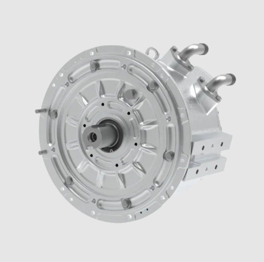
2.2 High Dynamic Response and Precise Control Capability
The dynamic superiority of the permanent magnet synchronous motor follows directly from its rotor construction. The rotor flux is produced by permanent magnets, so it is constant and establishes synchronism immediately. There is no field-winding time constant, no rotor circuit to energize, and no slip-dependent lag. This removes the excitation delay that limits the achievable bandwidth of induction machine torque control and establishes the physical basis for fast, linear torque production.
The mechanical dynamics of any driven roll can be written as:
$$J\frac{d\omega_m}{dt} = T_e – T_L – B\omega_m$$
where \(J\) is the total inertia referred to the motor shaft, \(T_e\) is electromagnetic torque, \(T_L\) is load torque, and \(B\) is the viscous friction coefficient. Because the permanent magnet synchronous motor has a robust rotor with low inertia and produces torque that is proportional to the quadrature-axis current within the linear magnetic region:
$$T_e = \frac{3}{2}p\left[\psi_f i_q + (L_d – L_q)i_d i_q\right]$$
the achievable angular acceleration for a given current is high and predictable. The resulting electromechanical time constant is small, and torque and speed responses in the millisecond range are achievable. In the reel, calender, and coater sections, where tension control is extremely sensitive, this matters directly. The drive must reject load and speed disturbances quickly enough that the web never experiences a tension excursion large enough to cause a break or a defect. The fast electromagnetic and mechanical response of the permanent magnet synchronous motor provides exactly that rejection capability.
There is a second, less obvious benefit. When several driven points must remain synchronized, the quality of synchronization depends on how uniform and repeatable each individual drive’s response is. The permanent magnet synchronous motor, being free of slip and of rotor parameter drift, behaves more consistently across drives than an induction machine does. This uniformity is a precondition for the master-slave and load-sharing architectures used on modern paper machines.
2.3 High Torque and Power Density, and Wide Speed Range
The permanent magnet synchronous motor produces more torque per unit volume and more power per unit mass than a comparable induction machine. Torque density can be expressed as:
$$\rho_T = \frac{T_e}{V_{rotor}} \propto \frac{\psi_f i_q}{V_{rotor}}$$
Because the magnet supplies a high air-gap flux density without requiring a magnetizing current component, the same frame can deliver noticeably more output. In papermaking this has an immediate architectural consequence: drives can be made more compact, and machine layouts can be simplified.
The more consequential property is the wide, smooth speed range with constant torque capability at low speed. This combination eliminates the need for gearboxes in many positions. The relationship between web line speed and roll rotational speed is:
$$v = \frac{\pi D n}{60}$$
where \(v\) is web speed in m/s, \(D\) is roll diameter in metres, and \(n\) is rotational speed in r/min. In conventional installations, the motor must run at a speed far above the required roll speed, and a gearbox bridges the gap. That gearbox consumes energy, generates noise, requires lubrication and maintenance, and introduces backlash and torsional compliance. A direct-drive permanent magnet synchronous motor removes all of it.
| Attribute | Geared induction drive | Direct-drive permanent magnet synchronous motor |
|---|---|---|
| Transmission chain | Motor + gearbox + coupling | Motor coupled directly to roll |
| Gear losses | Present at all operating points | Eliminated |
| Backlash and torsional compliance | Present | Negligible |
| Noise and vibration | Higher | Lower |
| Maintenance items | Oil, seals, bearings, gears | Bearings only |
| Dynamic stiffness | Reduced by gearbox inertia | High |
| Footprint and mass | Larger | Compacter and lighter |
The result of direct driving is a shorter, stiffer transmission chain, faster response, higher overall reliability, and improved energy efficiency. These are precisely the characteristics that high-speed, high-precision papermaking equipment demands.
2.4 High Reliability and Low Maintenance
The permanent magnet synchronous motor has no brushes and no slip rings. Mechanical wear from sliding electrical contact and the risk of electrical sparking are therefore eliminated at the source, which raises intrinsic reliability and extends service life. In the paper mill environment, where temperature is elevated, humidity is high, and airborne dust and fiber are ubiquitous, this structural simplicity is particularly valuable. Longer maintenance intervals and lower maintenance cost have a direct effect on line availability, and reduced unplanned downtime is one of the largest economic benefits a mill can obtain from a drive retrofit.
3. Control Strategies and Their Mapping onto Papermaking Duties
The performance advantages of the permanent magnet synchronous motor are realized only through appropriate control. Over time, a layered family of strategies has developed, balancing dynamic accuracy, energy efficiency, and economic cost. Their selection is governed by the duty profile of the driven point rather than by a single global preference.
3.1 Constant Volts-per-Hertz Open-Loop Control
The simplest approach maintains a constant ratio between stator voltage magnitude and supply frequency in order to keep the air-gap flux approximately constant:
$$\frac{V}{f} = \text{constant} \quad \Rightarrow \quad \psi_s \approx \frac{V}{2\pi f} \approx \text{constant}$$
This method is structurally simple and requires no rotor position sensor, but its dynamic response is slow, its steady-state accuracy is limited, and it can lose synchronism under abrupt load changes. In the paper mill it is appropriate for shop ventilation fans, circulating water pumps, and conveyor drives, where operation is continuous and load variation is mild. The value of volts-per-hertz control with a permanent magnet synchronous motor lies in combining basic speed regulation and energy saving with minimal system complexity and maintenance burden.
3.2 Field-Oriented Vector Control
Field-oriented control transforms the stator quantities into a reference frame aligned with the rotor flux, decoupling the stator current into a flux-producing component and a torque-producing component. The stator voltage equations in the rotor reference frame are:
$$u_d = R_s i_d + L_d \frac{di_d}{dt} – \omega_e L_q i_q$$
$$u_q = R_s i_q + L_q \frac{di_q}{dt} + \omega_e\left(L_d i_d + \psi_f\right)$$
This decoupled structure gives the permanent magnet synchronous motor a wide speed range, high steady-state accuracy, and fast dynamic response, and it forms the technical foundation for all high-precision paper machine drives. In papermaking practice, a cascade structure with an outer speed loop and an inner current loop is standard, and it satisfies the speed and torque control requirements of stock preparation, calendering, and rewinding.
Surface-Mounted Machines with Zero Direct-Axis Current
For a surface-mounted permanent magnet synchronous motor, the direct-axis and quadrature-axis inductances are essentially equal. The reluctance torque term in the torque equation therefore vanishes and torque becomes purely proportional to quadrature-axis current:
$$T_e = \frac{3}{2}p\,\psi_f i_q \quad \text{when} \quad i_d = 0$$
Setting the direct-axis current reference to zero is simple, gives good dynamic response, and is easy to implement. In the paper mill this combination is appropriate where dynamic demands are moderate but reliability and cost effectiveness matter. Typical applications include pulper drives, where stable torque control supports uniform fiber treatment; pumps and fans such as stock pumps, vacuum pumps, and drying-section ventilation fans, where accurate flow and pressure regulation yields energy savings; and ancillary units such as additive preparation and effluent treatment. I consider this the mainstream solution for the large population of auxiliary drives in a mill, delivering an excellent ratio of benefit to cost.
Interior Machines with Maximum Torque Per Ampere
For an interior permanent magnet synchronous motor, the saliency of the rotor makes the direct-axis inductance smaller than the quadrature-axis inductance, so the reluctance torque contribution is significant. Maximizing torque per unit stator current yields the maximum torque per ampere condition:
$$i_d = \frac{\psi_f}{2\left(L_q – L_d\right)} – \sqrt{\frac{\psi_f^2}{4\left(L_q – L_d\right)^2} + i_q^2}$$
This strategy computes the optimal combination of direct-axis and quadrature-axis currents in real time, exploiting both magnet torque and reluctance torque. The result is higher efficiency, higher torque density, and better dynamic performance for a given inverter current rating. These characteristics match the requirements of high-speed, heavily loaded core papermaking equipment. In current practice, interior permanent magnet synchronous motors with maximum torque per ampere control form the mainstream electrical solution for the dryer section, the vacuum couch roll, the wire driving roll, high-precision rewinders, and heavy calenders, where torque accuracy and dynamic response directly determine web formation quality, drying uniformity, winding tension, and sheet thickness stability.
| Current component | Physical role | Control objective | Effect on efficiency |
|---|---|---|---|
| Direct-axis current \(i_d\) | Flux weakening or flux aiding | Voltage limit satisfaction, reluctance torque generation | Negative \(i_d\) raises copper loss but enables higher speed |
| Quadrature-axis current \(i_q\) | Torque production | Torque tracking | Linear relation with torque in the magnet-only case |
| Current vector angle | Distribution between axes | Maximum torque per ampere or maximum torque per volt | Optimal angle minimizes current for a given torque |
3.3 Sensorless Vector Control
Sensorless vector control replaces the physical rotor position transducer with an online estimator that reconstructs rotor position and speed from measured stator voltages and currents, using either the machine model or the saliency signature. The core of the method is a high-accuracy, high-robustness observer whose output is fed back into the vector control loop.
The back electromotive force components in the stationary frame are:
$$e_\alpha = -\omega_e \psi_f \sin\theta_e, \qquad e_\beta = \omega_e \psi_f \cos\theta_e$$
A sliding-mode observer reconstructs the stator current and extracts the disturbance term containing the back electromotive force:
$$\frac{d\hat{i}_\alpha}{dt} = \frac{1}{L_s}\left(u_\alpha – R_s \hat{i}_\alpha – \hat{e}_\alpha\right)$$
Estimator families fall into two broad groups. Model-based methods, including sliding-mode observers and extended Kalman filters, are generally applicable in the medium and high speed region. Saliency-tracking methods, notably high-frequency signal injection, are the key to stable observation at zero and low speed.
| Control strategy | Position sensor | Effective speed range | Dynamic response | Steady-state accuracy | Representative papermaking duty |
|---|---|---|---|---|---|
| Constant volts-per-hertz | Not required | Moderate | Slow | Low | Ventilation fans, circulating pumps, conveyors |
| Field-oriented with \(i_d = 0\) | Required | Wide | Fast | High | Pulpers, stock pumps, additive preparation |
| Field-oriented with maximum torque per ampere | Required | Wide | Very fast | Very high | Dryer cylinders, vacuum couch roll, calenders, rewinders |
| Sensorless vector control | Not required | Wide, with limits at low speed | Fast | Medium to high | Auxiliary drives, low-dynamic main drives |
In the continuous production context of a paper mill, sensorless control reduces dependence on mechanical position transducers, lowers hardware complexity, and mitigates the risk of sensor failure caused by high temperature, humidity, and dust. These characteristics improve operational stability and environmental adaptability. The technology is therefore appropriate for variable-frequency pump and fan systems serving the mill, and also for main-process equipment with lower dynamic requirements, such as pulpers, agitators, low-speed conveyors, and parts of the stock preparation line.
I must, however, be explicit about the limits. The suitability of sensorless control varies substantially by process section. In pulping, conveying, ventilation, and pumping duties, where load variation is gradual and precision demands are modest, sensorless control meets the speed regulation requirement while lowering cost and failure rate. In rewinding, calendering, and coating, where tension precision and dynamic response are demanding, the estimation error and parameter sensitivity of sensorless schemes can degrade tension stability, particularly during low-speed starts and at high line speed. Those sections generally continue to use closed-loop control with high-resolution encoders. On a high-speed machine, sensorless control is best applied to auxiliary drives; where multi-motor synchronization and high-precision tension control are required, it should be combined with high-performance observers or used alongside position-sensed strategies.
4. An Application-Oriented Control Technology System
The composite demands of a paper machine, namely high efficiency, high dynamics, and high coordination, have driven the evolution of a family of targeted control solutions. I group them into three dimensions: high-efficiency control for energy saving across the whole process, high-dynamic coordinated control for critical quality-determining sections, and synchronous control for coordinated operation of the entire line.
4.1 High-Efficiency Control for the Whole Process
4.1.1 Field Weakening and Loss Suppression over a Wide Speed Range
Field weakening is the key technique for extending the high-speed operating range of the permanent magnet synchronous motor while maintaining acceptable efficiency. When speed exceeds the base speed, the available inverter voltage is insufficient to drive the required current against the rising back electromotive force. Injecting a negative direct-axis current reduces the air-gap flux and restores voltage balance, allowing operation in the constant-power region:
$$\left(L_d i_d + \psi_f\right)^2 + \left(L_q i_q\right)^2 \le \left(\frac{u_{dc}}{\sqrt{3}\,\omega_e}\right)^2$$
$$i_d^2 + i_q^2 \le I_{max}^2$$
In papermaking, dryer sections and high-speed rewinders must operate across a wide speed range, and field weakening provides the necessary technical support. Beyond extending the speed range, it also helps suppress iron loss and eddy-current loss at high speed, improving overall system efficiency.
The applicability of field weakening depends on the speed range actually required by each duty. Equipment that operates only below base speed, such as pulpers and agitators, needs no field weakening at all. Equipment that operates intermittently in the field-weakening region, such as a rewinder during acceleration and deceleration, can use a simple field-weakening strategy. Core drives that run continuously at high speed, such as turbine vacuum pumps and drying cylinders, require high-performance field weakening, and here the risk of irreversible magnet demagnetization from excessive weakening must be managed carefully.
| Duty category | Speed range requirement | Field weakening need | Demagnetization risk | Recommended strategy |
|---|---|---|---|---|
| Pulpers, agitators, mixers | Below base speed | None | Very low | Constant torque control |
| Rewinders, intermittent acceleration | Occasional excursion above base speed | Simple | Low | Basic field weakening with current limit |
| Turbine vacuum pumps | Continuous high speed | Essential | Moderate | Adaptive field weakening with voltage margin supervision |
| Dryer cylinder groups | Wide, extended | Essential | Moderate to high | Hybrid excitation or online magnet temperature monitoring |
Current research focuses on improving the dynamic performance and robustness of field weakening, including linear field-weakening control, adaptive field weakening based on available voltage margin, and hybrid excitation topologies that reduce reliance on demagnetizing current. Combining field weakening with position-sensorless techniques is another direction that simplifies system structure.
4.1.2 Intelligent Energy Optimization Algorithms
Intelligent energy optimization algorithms sense motor and process state in real time and adjust control commands dynamically so that efficiency is optimal under changing conditions. Their essential role is to process operating data and optimize key control variables online, such as proportional-integral-derivative gains and current references.
The objective can be formulated as a constrained optimization problem:
$$\min_{u \in U} \; J = \int_0^T \left[\alpha\, e(t)^2 + \beta\, u(t)^2\right] dt$$
where \(e(t)\) is the tracking error and \(u(t)\) is the control effort. In a multi-stage, variable-load continuous process such as papermaking, such algorithms improve efficiency under complex conditions. Swarm-intelligence methods, including ant colony optimization and particle swarm optimization, have been applied to adaptive tuning of the proportional-integral-derivative parameters in paper machine speed chains, improving dynamic response while reducing energy consumption.
Furthermore, condition-aware real-time energy management strategies can combine information such as roll diameter variation and load ratio to adjust motor control parameters dynamically, keeping the system at a high efficiency level across different operating phases. This represents a shift from local optimization to system-level energy coordination.
From the standpoint of process suitability, intelligent optimization algorithms are best applied to sections with complex conditions and frequent load fluctuation, such as rewinder load allocation, multi-axis coordination in the machine speed chain, and tension coordination between the drying and sizing sections. In these duties, online parameter optimization improves the ability of the system to cope with uncertainty. At the same time, practical deployment is constrained by computational complexity, real-time requirements, and model accuracy. For auxiliary equipment operating in a relatively steady state, such as fans and pumps, conventional control already satisfies the energy-saving requirement, and introducing complex optimization may only increase implementation cost. The depth and complexity of the optimization layer should therefore be matched deliberately to the dynamics and saving potential of each duty.
4.1.3 Temperature-Adaptive Modulation
Temperature-adaptive modulation addresses the parameter drift and performance degradation caused by thermal variation, and it is essential for stable, efficient operation in demanding thermal environments. The technique integrates real-time temperature sensing and adjusts the control strategy to compensate for thermally induced parameter changes, redistribute losses, and prevent overheating.
The remanence of the permanent magnet varies with temperature according to:
$$\psi_f(T) = \psi_{f0}\left[1 + \alpha_B\left(T – T_0\right)\right]$$
where \(\alpha_B\) is the reversible temperature coefficient of the magnet material, negative for the rare-earth magnets commonly used. As magnet flux falls with rising temperature, the torque constant falls as well, and the control system must compensate. The stator resistance also rises with temperature, altering the current loop dynamics. If these effects are ignored, torque accuracy degrades and the risk of thermal runaway or demagnetization increases.
The value of temperature-adaptive modulation is most evident in high-speed turbine vacuum pump drives and in the large drives of rewinders and calenders. Turbine vacuum pump motors operate continuously in the high-speed region, where high switching frequency causes significant loss and temperature rise. Through temperature-adaptive modulation the system can adjust switching frequency or modulation mode based on thermal feedback, suppressing temperature rise while maintaining vacuum performance. In rewinders and calenders, large motors may develop local overheating at low speed and high torque or at high speed because of harmonic effects. Dynamic optimization of the modulation strategy suppresses harmonics and balances loss distribution, avoiding magnet demagnetization and insulation ageing.
Suitability depends on thermal sensitivity and temperature rise characteristics. For short-time-duty or lightly loaded equipment, temperature rise is modest and complex thermal management is unnecessary. For core equipment operating continuously under heavy load, temperature-adaptive functionality should be integrated and combined with non-invasive online temperature estimation, such as high-frequency injection methods, to form a closed thermal management loop. The field is moving from passive thermal protection toward active thermal optimization, coordinating performance, efficiency, and thermal reliability.
| Technology | Primary mechanism | Efficiency dimension addressed | Preferred papermaking duty |
|---|---|---|---|
| Field weakening | Negative direct-axis current reduces flux | Extends efficient high-speed range | Dryer sections, turbine vacuum pumps, rewinders |
| Intelligent energy optimization | Online parameter and reference optimization | Dynamic energy optimum under varying load | Rewinder load allocation, speed chain coordination |
| Temperature-adaptive modulation | Thermal feedback adjusts switching and modulation | Preserves efficiency and reliability under thermal stress | High-speed vacuum pumps, heavy calenders |
Taken together, field weakening, intelligent energy optimization, and temperature-adaptive modulation support deep energy saving along three axes: broadening the efficient operating range, achieving dynamic energy optimality, and preserving environmental robustness. In practice, the appropriate combination must be selected according to the speed range, load fluctuation characteristics, and thermal load of each section, with attention to compatibility with the underlying field-oriented control strategy and to implementation cost.
4.2 High-Dynamic Coordinated Control for High-Speed Rewinding
In high-speed papermaking, the rewinder, calender, and coater sections impose severe dynamic requirements on the drive system. Machines operating above 800 m/min are commonly classified as high-speed, and for high-speed fine paper machines the operating speed typically reaches 1500 to 2000 m/min. Above 1500 m/min, if torque and speed responses lag during acceleration, deceleration, or load fluctuation, tension loss and web breaks become likely. The high-dynamic control capability of the permanent magnet synchronous motor is precisely the means by which tension fluctuation and break risk are managed at high speed.
The high-speed rewinder is the most demanding case. Its control difficulty lies in achieving accurate, strongly coupled control of web tension, running speed, and rewinding force simultaneously. Four control functions dominate: web speed control, executed by the rear bottom roll, whose rotational speed determines web speed and which must provide a minimum threading speed and an S-shaped acceleration profile; tension control, executed by the unwinding roll, which generates braking torque to hold tension constant and whose algorithm must include real-time roll diameter calculation, dynamic torque compensation, and tension braking; rewinding force control, produced by the driving force difference between the front and rear bottom rolls, which directly affects roll hardness and therefore requires load allocation between the two rolls; and nip pressure control, executed by the rider roll, which maintains stable contact pressure between the roll and the bottom rolls to ensure roll formation quality.
4.2.1 Two-Degree-of-Freedom Coordination of Front and Rear Bottom Rolls
To regulate speed and tension independently and precisely, the high-speed rewinder drive system adopts a two-degree-of-freedom speed-torque architecture. The rear bottom roll is established as the speed reference for the whole machine and implements speed-dominant control, while the front bottom roll acts as the actuator for rewinding force and torque adjustment.
The rear bottom roll uses a cascade speed and current loop structure. The inner loop is a field-oriented current loop, while the outer loop detects roll surface line speed through a high-resolution encoder and closes the loop on it, ensuring that machine speed follows the reference exactly and providing a stable speed basis for the system.
The front bottom roll control system supports both a speed-following mode and a torque-control mode, with bumpless transfer between them. During startup, speed change, and shutdown, the front bottom roll operates in speed-following mode, its reference synchronized with the rear bottom roll, so that web line speed remains identical and tension shock during transients is avoided. Once steady-state constant-speed rewinding is reached, the front bottom roll switches to torque-control mode. In this mode the system uses the real-time torque output of the rear bottom roll and a predefined load allocation algorithm to generate the torque reference for the front bottom roll dynamically, thereby controlling roll hardness precisely.
$$T_{front}^{ref} = k_{alloc}\,T_{rear}^{meas} + T_{comp}\left(\omega, R, \dot{R}\right)$$
This two-degree-of-freedom architecture achieves a clear functional division and dynamic coordination between the speed loop and the torque loop, and it is the core mechanism that guarantees stable tension and uniform roll formation at high speed.
4.2.2 Constant-Tension High-Dynamic Torque Control of the Unwinding Roll
Constant tension control at the unwinding roll is the key to both rewinding quality and break prevention. The drive must have four-quadrant capability, operating in speed mode during startup to synchronize and then in torque-control mode in the third quadrant during normal rewinding, with the core task of holding unwinding tension constant. At high speed, the dynamic performance of the unwinding roll’s torque response directly determines tension control quality.
The torque reference for constant tension operation is:
$$T^{ref} = \frac{F \cdot R}{i} + \frac{J}{i}\frac{d\omega_m}{dt} + T_{loss}$$
where \(F\) is web tension, \(R\) is the instantaneous unwinding roll radius, \(i\) is the transmission ratio, \(J\) is the total inertia, and \(T_{loss}\) represents friction and windage. The first term is the tension-producing torque, the second is the inertial compensation term required during acceleration and deceleration, and the third compensates losses. Because the radius decreases continuously, the inertial term and the tension term both change during operation, and accurate radius estimation is essential.
Radius can be estimated online from the ratio of web speed to angular speed, and updated recursively from the wound thickness per revolution:
$$\hat{R} = \frac{v}{\omega_m}$$
$$\frac{dR}{dt} = -\frac{h\,\omega_m}{2\pi}$$
where \(h\) is the sheet thickness including interlayer air. The system performance bottleneck is the response speed of the current loop and the accuracy of feedforward compensation: the former determines how quickly disturbances are suppressed, while the latter determines tension holding capability in the steady state. Advanced algorithms such as field-programmable-gate-array-based model predictive control can achieve current-loop control periods in the microsecond range. Model predictive control performs online rolling optimization with feedback correction and directly controls electromagnetic torque and flux linkage, effectively suppressing torque ripple and improving tension smoothness:
$$J_{MPC} = \sum_{k=1}^{N_p}\left\|i_{dq}(k) – i_{dq}^{ref}\right\|^2 + \lambda \sum_{k=1}^{N_c-1}\left\|\Delta u(k)\right\|^2$$
Combined with four-quadrant operation of the drive, this system accommodates the rapid acceleration and deceleration demands of the unwinding process. With online radius identification and dynamic torque compensation, high-precision constant tension control can be achieved even at very high line speeds. Studies on radius-estimation-based tension control report tracking errors within approximately ±1.58% over a wide speed range, with dynamic tension fluctuation during acceleration and deceleration held within the ±2% industry benchmark, providing reliable support for stable production at ultra-high rewinding speeds.
| Control function | Actuator | Control mode | Key algorithm | Primary quality target |
|---|---|---|---|---|
| Web speed | Rear bottom roll | Speed closed loop with encoder | Field-oriented control with S-curve ramping | Stable machine speed and smooth acceleration |
| Rewinding force | Front bottom roll | Speed following mode and torque mode with bumpless transfer | Load allocation based on rear roll torque | Uniform roll hardness |
| Web tension | Unwinding roll | Torque control in the third quadrant | Online radius estimation with dynamic feedforward compensation | Constant tension, no breaks |
| Nip pressure | Rider roll | Pressure or position control | Contact pressure regulation | Roll formation quality |
4.2.3 Advanced Algorithms in High-Dynamic Scenarios
Beyond strategies applied to specific actuators, a family of advanced control algorithms improves the dynamic performance of permanent magnet synchronous motor drive systems as a whole. Linear active disturbance rejection control uses an extended state observer to estimate and compensate the total internal and external disturbance in real time, significantly enhancing robustness against load fluctuation and supply disturbance. Linear quadratic optimal control systematically optimizes state feedback to coordinate the dynamic relationships among speed, torque, and flux linkage, providing a theoretical framework for fast and smooth reference tracking. These algorithms show clear potential in paper machine multi-section drives, where synchronization accuracy and disturbance rejection requirements are extremely high.
In summary, customized high-dynamic control designs for the different actuators of the rewinder, combined with advanced algorithms such as model predictive control and active disturbance rejection control, give the permanent magnet synchronous motor drive system the technical capability required for high-speed rewinding. Together these technologies solve the problem of accurate tension control and system robustness under high-speed, variable-load conditions, and they establish the foundation for efficient and stable production of high-quality paper.
4.3 Synchronous Control for Coordinated Operation of the Entire Machine
On a modern high-speed paper machine, a fine paper machine running at 1500 to 2000 m/min for example, the entire process from forming section to reel is driven by more than a hundred distributed permanent magnet synchronous motors that together draw a single continuous web. Ensuring that the web runs continuously and without breaking while undergoing complex physical and chemical changes imposes several stringent requirements on multi-motor coordination.
First, the extensibility of the web differs markedly between process stages, so the speed ratios between driven points must be extremely precise and continuously adjustable. Any small mismatch accumulates as stretch or slack and directly threatens sheet quality and runnability. Second, when several motors jointly drive a wide roll such as a dryer cylinder, dynamic load must be balanced precisely to prevent local overload and torque fighting. Third, a long process with large inertia is easily disturbed locally, so the control system must possess strong disturbance rejection and robust stability. The synchronous control technology system has been developed to meet these challenges.
4.3.1 Speed Chain Synchronization and Draw Ratio Control
Speed chain control is the foundation of line-wide speed coordination and accurate process draw matching. In the standard architecture, the first wire driving roll serves as the master speed reference for the whole line, and every subsequent driven point, including each section roll, dryer group, size press roll, calender roll, and the reel, acts as a speed slave. Each slave receives and tracks the speed reference and process draw coefficient from the master unit or from the preceding slave over a high-speed real-time industrial network, forming a globally synchronized distributed control system whose draw ratios can be reconfigured online.
$$v_i = k_i \, v_{master}, \qquad k_i = \prod_{j \le i} r_j$$
where \(r_j\) is the local draw ratio between adjacent sections. The core of this architecture is the establishment and maintenance of clear and stable master-slave relationships. Its main objectives are twofold. The first is to guarantee strict line speed synchronization between adjacent driven points that have a mechanical hard connection, thereby avoiding roll surface wear, sheet stretching, or wrinkling caused by speed deviation. The second is to provide high-resolution, real-time-adjustable draw ratio setting to accommodate the precise micro-strain requirements of different grades, basis weights, and processes during dewatering, drying, and coating.
The technical realization depends on two tightly coupled aspects. Locally, each permanent magnet synchronous motor drive station uses field-oriented control with high-resolution encoder or multi-turn absolute encoder feedback, forming a stable and fast speed-tracking inner loop. At the system level, a high-performance global communication and clock synchronization mechanism ensures low-latency, highly deterministic transmission of speed references, draw parameters, state feedback, and control data across all distributed nodes, with nanosecond-order clock accuracy. This combination is the core technical support for coordinated operation of a long, multi-node drive system.
4.3.2 Load Allocation and Tension Coordination
For the challenge of load balancing where multiple motors drive the same load zone, load allocation control must be introduced on top of speed synchronization. Typically one motor is designated as the speed master and the others as torque slaves. The slave motors use torque closed-loop control, and their torque references are generated dynamically from the master motor torque, total load, and real-time conditions through a specific optimization algorithm such as proportional allocation or optimal load sharing:
$$T_i = \frac{\alpha_i}{\sum_{j=1}^{n}\alpha_j} \, T_{total}, \qquad \sum_{i=1}^{n} T_i = T_{load}$$
This achieves automatic equalization of drive effort, prevents the phenomena of one drive grabbing load while another lags, keeps load allocation error at a low level, and safeguards equipment safety and operating efficiency.
For the long-process challenges of disturbance rejection and maintaining tension stability between process sections, tension coordination control is the key measure. At the junction between the size press and the drying section, for example, web tension is measured in real time or estimated by model-based soft sensing, and this value is used as an advanced feedback quantity to coordinate the speed or torque references of adjacent section drives, forming a closed-loop tension regulation that actively suppresses disturbance and maintains stable web tension, preventing the slack or overstretch that causes wrinkles and breaks. The span tension dynamics can be expressed as:
$$\frac{dF}{dt} = \frac{E A}{L}\left(v_2 – v_1\right)$$
where \(E\) is the elastic modulus of the web, \(A\) is its cross-sectional area, \(L\) is the span length, and \(v_1\) and \(v_2\) are the speeds of the upstream and downstream rolls. This relationship shows that tension is controlled by the speed difference between adjacent sections, which is precisely why the draw ratio accuracy of the speed chain matters so much, and why the fast, uniform response of the permanent magnet synchronous motor is a prerequisite for tight tension regulation.
In recent years, advanced cooperative control methods have been introduced to further improve overall system performance and robustness. Consensus protocols based on multi-agent system theory treat multiple permanent magnet synchronous motors as a single cooperative network, achieving distributed high-precision synchronization and significantly improving convergence speed and robustness to external disturbance:
$$\dot{x}_i(t) = \sum_{j \in N_i} a_{ij}\left(x_j(t) – x_i(t)\right)$$
Finite-time integrated cooperative control methods based on higher-order sliding-mode observers can estimate and compensate lumped disturbances in real time, including load variation and model uncertainty, and generate more accurate compensation commands directly within the field-oriented control framework, demonstrating stronger disturbance rejection and dynamic performance.
| Coordination layer | Control objective | Key variables | Representative method |
|---|---|---|---|
| Speed chain | Line-wide synchronous speed with adjustable draw | Speed reference, draw ratio | Master-slave tracking over real-time Ethernet |
| Load allocation | Balanced torque sharing among motors on a common load | Torque reference, allocation coefficient | Proportional or optimal load sharing |
| Section tension | Stable web tension between process stages | Speed difference, tension estimate | Closed-loop tension feedback with soft sensing |
| Networked cooperation | High-precision distributed synchronization with robustness | Consensus state, disturbance estimate | Multi-agent consensus and sliding-mode observers |
Synchronous control technology, through global speed chain synchronization, dynamic load allocation, coordinated tension regulation, and advanced disturbance-rejection algorithms, constitutes the control backbone of a stable modern high-speed paper machine. As industrial internet connectivity, digital twins, and artificial intelligence techniques continue to penetrate the field, synchronous control systems are evolving toward intelligence, adaptivity, and predictive maintenance, promising further gains in multi-motor synchronization accuracy and system robustness.
5. Industrial Connectivity and Cooperative Optimization
Against the background of deep integration between intelligent manufacturing and the industrial internet, the permanent magnet synchronous motor has become the core drive unit of the green and intelligent transformation of the modern paper industry. To release its potential further, building a cooperative optimization system based on industrial connectivity is a key direction. Such a system integrates smart factory architecture, digital twin technology, and multi-dimensional cooperation strategies, moving papermaking production from stand-alone control toward whole-process optimization.
5.1 Smart Factory Architecture and Data Fusion
I conceptualize the smart factory as a three-layer structure. The device layer contains the permanent magnet synchronous motor itself together with sensors, encoders, and power conversion hardware. The motion control layer implements coordinated control of multiple permanent magnet synchronous motors over a high-speed industrial network, executing the speed chain, load allocation, and tension coordination functions described above. The data and security layer performs system-wide data integration and security management, and provides the analytical services on which higher-level optimization depends. This architecture provides a complete technical path from stand-alone monitoring to system-level optimization and establishes the data-driven foundation for cooperative control.
| Layer | Contents | Primary function | Time scale |
|---|---|---|---|
| Data and security layer | Historian, analytics, cybersecurity, cloud services | Data integration, model execution, decision support | Seconds to days |
| Motion control layer | Multi-axis controllers, real-time network, drive coordination | Synchronization, load sharing, tension regulation | Microseconds to milliseconds |
| Device layer | Permanent magnet synchronous motor, sensors, converters | Torque production, state sensing | Microseconds |
5.2 Digital Twin Enabled Virtual Commissioning and Predictive Maintenance
Digital twin technology builds a digital mapping of the permanent magnet synchronous motor and its drive system, providing virtual commissioning, condition monitoring, and predictive maintenance support for papermaking equipment. Before the system is placed in service, the motor model and control parameters can be used for virtual commissioning, which shortens the on-site commissioning period substantially, in representative cases by around forty percent, and significantly reduces integration risk. During operation, real-time comparison between the physical system and the digital model allows potential faults such as magnet demagnetization and bearing wear to be identified early, shifting the maintenance paradigm from reactive repair to predictive maintenance and improving the continuity and reliability of paper production.
The digital twin also provides a safe environment for control parameter optimization. Because the virtual model can be exercised across operating conditions that would be risky or expensive to reproduce on the real machine, tuning of field-weakening boundaries, current-loop gains, and load allocation coefficients can be carried out offline and then deployed with confidence. This is particularly valuable for the permanent magnet synchronous motor, whose parameter variations with temperature and load make purely empirical tuning unreliable.
5.3 Multi-Level Cooperative Optimization
Within the industrial internet framework, cooperative optimization of the permanent magnet synchronous motor covers three levels.
At the motor system level, high-speed real-time industrial networks enable synchronous operation and dynamic load allocation among multiple permanent magnet synchronous motors, establishing accurate draw relationships between paper machine sections and holding multi-axis synchronization error at a very low level. This level of cooperation is the basis for stable web tension and break prevention, and its performance is limited by network latency, clock synchronization accuracy, and the robustness of the load allocation algorithm.
At the production process level, motor operating data and process parameters are used to build an optimization and scheduling model covering the whole flow from pulping and forming to calendering and rewinding. By sensing the energy state and production progress of each stage in real time, production tempo and process parameters are adjusted dynamically, reducing waiting time between stages and idle energy consumption, and realizing on-demand energy supply and flexible production. The essence of this level is to break down the information silos between process stages and establish a mechanically, electrically, and technologically integrated data linkage.
At the energy management level, the motor drive system, the drying section heat pump system, the vacuum system, and the compressed air system are integrated into a plant-level energy allocation optimization model covering multiple energy carriers. The objective can be expressed as:
$$\min_{u \in U} \sum_{k=1}^{N}\left[c_e(k)\,P_k(u) + c_g(k)\,G_k(u) + c_s(k)\,S_k(u)\right]$$
where \(P_k\), \(G_k\), and \(S_k\) represent electrical, thermal, and steam energy flows for unit \(k\), and \(c_e\), \(c_g\), and \(c_s\) are the corresponding time-varying prices or carbon factors. By monitoring the load characteristics and price signals of each unit in real time, the allocation paths and cascade utilization strategies of energy among production units can be optimized dynamically. In the drying section, which is the largest energy consumer in papermaking, motor waste heat recovery can be coordinated with the heat pump system, linking motor operating state to drying heat demand and raising plant-level comprehensive energy efficiency. This level is a key support for carbon reduction targets, and its technical difficulties lie in the fusion of multi-source heterogeneous data, the modelling of complex energy flow networks, and the real-time performance and convergence of the optimization algorithms.
| Cooperation level | Scope | Decision variables | Benefit |
|---|---|---|---|
| Motor system | Multiple drives on one line | Speed references, draw ratios, torque allocation | Tension stability and break prevention |
| Production process | Whole mill process flow | Production tempo, process setpoints | Reduced waiting and idle energy |
| Energy management | Plant-wide energy carriers | Energy allocation and cascade utilization | Maximum comprehensive efficiency |
As industrial Ethernet and artificial intelligence technologies continue to evolve, the permanent magnet synchronous motor will be integrated more deeply into the intelligent ecosystem of the paper industry, forming a full-chain solution that combines intelligent motors, interconnected systems, and digital operations and maintenance, and providing solid technical support for the industry’s carbon reduction objectives.
6. Challenges and Future Directions
The current technology system still faces core challenges that prevent it from fully meeting the extreme and intelligent requirements of future papermaking.
Under ultra-high-speed conditions above 2500 m/min and with very wide webs, the robustness of existing control strategies against parameter variation and nonlinear disturbance needs improvement. The electrical and thermal parameters of the permanent magnet synchronous motor vary with operating point, and the web itself is a distributed, time-varying load. Model mismatch, sensor noise, and network-induced delay all limit achievable performance.
Under industrial internet architectures, the closed loop from data to information to decision is not yet fully closed, and the deployment of intelligent applications faces obstacles related to data quality, model credibility, and integration cost. Many mills have abundant data but insufficient actionable information.
The supply chain security and green recycling of high-performance rare-earth permanent magnet materials also constrain the sustainable development of the motor itself, and the environmental cost of magnet production must be accounted for when claiming net benefits from efficiency improvements.
Looking forward, I identify three directions where breakthroughs are needed to drive deep transformation of the paper industry.
First, developing artificial-intelligence-based adaptive robust control. For variable-load, strongly coupled conditions, research should combine data-driven methods with physical models, including deep reinforcement learning for parameter self-tuning and neural network observers, to break through the performance limits of conventional control and achieve high precision and strong robustness in tension and synchronization control under ultra-high-speed conditions.
Second, building a full-lifecycle digital twin and energy efficiency optimization system. A mechanically, electrically, and technologically integrated digital twin should be established so that real-time data fusion and cloud-based decision making enable online control parameter optimization, coordinated process adjustment, and global dynamic energy efficiency optimization.
Third, exploring new-generation motor materials and green design paradigms. The application of rare-earth-free permanent magnet materials and high-performance soft magnetic materials should be advanced to improve motor reliability under high temperature and high humidity, and a full-lifecycle carbon footprint assessment system should be established.
| Direction | Core problem | Enabling approach | Expected outcome |
|---|---|---|---|
| Adaptive robust control | Parameter variation and nonlinear disturbance | Physics-informed learning, reinforcement learning tuning, neural observers | High-precision tension and synchronization at extreme speed |
| Lifecycle digital twin | Broken data-to-decision loop | Integrated mechanical-electrical-process modelling with cloud analytics | Online optimization and whole-plant energy efficiency |
| Green motor materials | Rare-earth supply and recycling | Rare-earth-free magnets, advanced soft magnetic alloys | Sustainable and thermally robust drives |
7. Conclusions
In this review I have traced the role of the permanent magnet synchronous motor in papermaking from an efficiency-oriented replacement for the induction machine to a system-level enabler of green and intelligent production. The technical evolution follows a clear path: from single-machine efficient driving, to multi-motor decoupled cooperative control, and further to data-driven system-level intelligent control.
The advantages of replacing conventional induction machines with permanent magnet synchronous motors in papermaking are increasingly evident. Their high efficiency and wide-range direct-drive characteristics provide substantial energy savings and compact design options for high-consumption sections such as pulping and calendering. Their high dynamic response and precise control capability form the technical cornerstone for guaranteeing process quality and operational stability in high-speed rewinding and multi-motor synchronous drive systems.
Control strategies have advanced in step. From the economic application of zero direct-axis current control in auxiliary equipment, to the high-performance breakthroughs of maximum torque per ampere control and model predictive control in core equipment, and further to the reliability improvements offered by position-sensorless technology under harsh conditions, the evolution of control has consistently been organized around balancing energy efficiency, accuracy, and robustness. The permanent magnet synchronous motor is therefore best understood not as a component but as the node at which electrical engineering, control theory, mechanical design, and process technology meet in the modern paper mill. Through coordinated innovation in motor materials, control algorithms, and system integration, permanent magnet synchronous motor technology will continue to support the paper industry’s development toward higher efficiency, greater intelligence, and lower carbon operation, and the technical path it defines can serve as an important reference for the intelligent upgrading of process industries more broadly.