
I investigate how the can material of a canned permanent magnet synchronous motor influences three-phase short-circuit current and irreversible demagnetization. The permanent magnet synchronous motor is a 1.5 kW, 9000 r/min machine intended for vacuum-pump-like applications, where a thin metallic can separates the stator from the rotor and prevents process leakage. Although the can is geometrically thin, its electromagnetic properties can change the short-circuit current path, the d-axis and q-axis current peaks, the operating point of the permanent magnet, and the post-fault torque capability of the permanent magnet synchronous motor. I compare three stainless-steel can materials: SUS430, SUS316, and SUS304. SUS430 is a ferritic magnetic stainless steel, while SUS316 and SUS304 are austenitic nonmagnetic stainless steels. The central question I address is whether a magnetic can can raise the anti-demagnetization capability of a permanent magnet synchronous motor under a severe three-phase short-circuit fault, and if so, through which electromagnetic mechanism.
I use a field-circuit coupling method because a three-phase short-circuit fault in a permanent magnet synchronous motor is not only a magnetic-field problem. The external circuit determines how the phase currents evolve after the fault, while the magnetic field determines the flux linkage, the induced electromotive force, and the demagnetizing field seen by the permanent magnet. The permanent magnet synchronous motor therefore has to be represented together with its external short-circuit path. In my work, I combine a two-dimensional transient electromagnetic finite element model with an external circuit that closes the three-phase terminals at a selected instant. I then use the computed currents and fields to evaluate the demagnetization coefficient, air-gap flux density, stator tooth and yoke flux density, no-load induced electromotive force, and output torque before and after the fault. Finally, I explain the observed behavior using the no-load leakage flux coefficient and the permanent magnet operating point.
Machine Geometry and Material Inputs
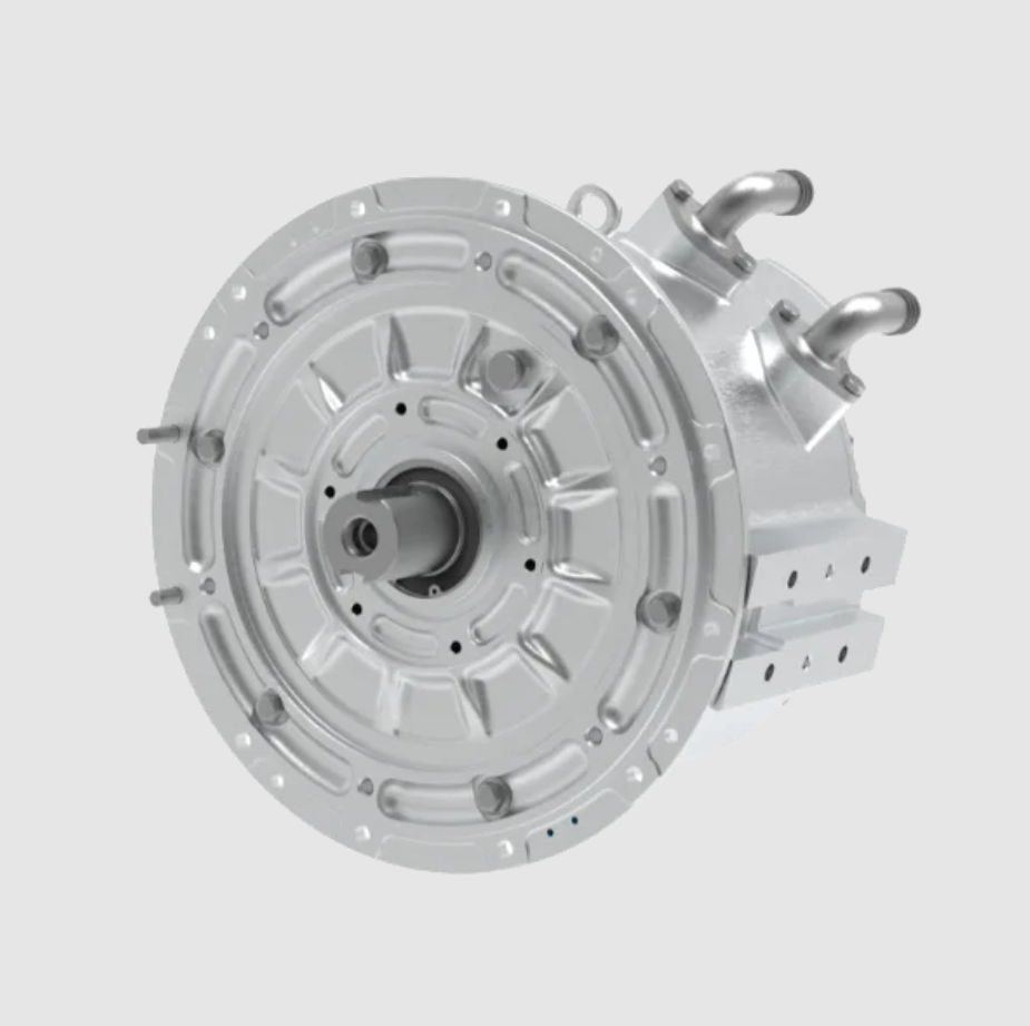
The permanent magnet synchronous motor I study has a surface-mounted permanent magnet rotor, a three-phase concentrated winding stator, nine slots, six poles, and three pole pairs. The rated voltage is 200 V, the rated power is 1.5 kW, and the rated speed is 9000 r/min. The stator outer diameter is 107 mm, the stator inner diameter is 50.5 mm, the air-gap length is 0.5 mm, and the axial length is 250 mm. The permanent magnet material is N38UH, and the can thickness is 0.5 mm. The current control strategy before the fault uses zero d-axis current, which is a common approach for surface-mounted permanent magnet synchronous motor drives. This detail matters because the pre-fault q-axis current is almost equal to the phase current amplitude, while the pre-fault d-axis current is approximately zero. Once the three-phase short circuit occurs, both the d-axis and q-axis currents oscillate, and the d-axis current becomes the main source of the demagnetizing field.
| Parameter | Value |
|---|---|
| Rated power | 1.5 kW |
| Rated voltage | 200 V |
| Rated speed | 9000 r/min |
| Stator outer diameter | 107 mm |
| Stator inner diameter | 50.5 mm |
| Air-gap length | 0.5 mm |
| Axial length | 250 mm |
| Number of slots | 9 |
| Number of poles | 6 |
| Number of pole pairs | 3 |
| Permanent magnet material | N38UH |
| Can thickness | 0.5 mm |
| Pre-fault current control | Zero d-axis current |
The three can materials differ mainly in magnetic permeability and electrical conductivity. SUS430 has a relative permeability of about 200, while SUS316 and SUS304 have relative permeabilities close to 1.0 to 1.1. Their electrical conductivities are similar in order of magnitude: SUS304 has the highest conductivity in my input set, followed by SUS316 and SUS430. This contrast allows me to separate the effect of permeability from the effect of conductivity. If the short-circuit behavior were dominated by conductivity, SUS304 and SUS316 would differ more strongly from each other. If permeability dominates the demagnetization behavior, SUS430 should behave differently from both nonmagnetic cans. My results show that permeability is the decisive parameter for the anti-demagnetization behavior of the permanent magnet synchronous motor, while conductivity has a secondary influence on leakage and demagnetization in the studied fault condition.
| Property | SUS316 | SUS430 | SUS304 |
|---|---|---|---|
| Metallurgical structure | Austenitic | Ferritic | Austenitic |
| Relative permeability | 1.1 | 200 | 1.0 |
| Electrical conductivity | 1.67 x 10^6 S/m | 1.33 x 10^6 S/m | 1.81 x 10^6 S/m |
| Density | 7.98 g/cm^3 | 7.70 g/cm^3 | 7.93 g/cm^3 |
| Elastic modulus | 193 GPa | 200 GPa | 193 GPa |
| Yield strength | at least 205 MPa | at least 205 MPa | at least 205 MPa |
| Tensile strength | at least 520 MPa | at least 420 MPa | at least 515 MPa |
Field-Circuit Coupling and Short-Circuit Model
For the transient electromagnetic field of the permanent magnet synchronous motor, I neglect displacement current because the frequencies and dimensions of the machine make the magnetoquasistatic approximation appropriate. The governing equation for the magnetic vector potential in the two-dimensional plane is
$$
\frac{\partial}{\partial x}\left(\frac{1}{\mu}\frac{\partial A_z}{\partial x}\right)
+
\frac{\partial}{\partial y}\left(\frac{1}{\mu}\frac{\partial A_z}{\partial y}\right)
=
-J_s
+
\sigma\frac{\mathrm{d}A_z}{\mathrm{d}t}
$$
where the magnetic vector potential has only the z-directed component, the material permeability is represented by the symbol mu, the conductivity is represented by the symbol sigma, and the source current density is represented by the symbol J_s. The outer boundary condition I apply is
$$
A_z|_{\Gamma}=0
$$
The external circuit is coupled to the field model through the phase flux linkages. For each phase, the voltage equation is
$$
v_a = R_s i_a + \frac{\mathrm{d}\psi_a}{\mathrm{d}t}
$$
$$
v_b = R_s i_b + \frac{\mathrm{d}\psi_b}{\mathrm{d}t}
$$
$$
v_c = R_s i_c + \frac{\mathrm{d}\psi_c}{\mathrm{d}t}
$$
When the three-phase short circuit is applied, the terminal voltages are forced to satisfy the short-circuit constraint, and the phase currents evolve according to the flux linkages and the stator resistance. The permanent magnet synchronous motor therefore experiences a transient current that contains both a decaying direct-current component and an alternating component. The instant of fault initiation is chosen when the phase flux linkage reaches its peak. In my model, this occurs at 2.43 ms, because this condition produces the most severe short-circuit current and the strongest demagnetizing field. The same condition is used for all three can materials so that the comparison is fair.
I also transform the phase currents into the rotor d-q reference frame. The transformation I use is
$$
i_d =
\frac{2}{3}
\left[
i_a\cos\theta_e
+
i_b\cos\left(\theta_e-\frac{2\pi}{3}\right)
+
i_c\cos\left(\theta_e+\frac{2\pi}{3}\right)
\right]
$$
$$
i_q =
-\frac{2}{3}
\left[
i_a\sin\theta_e
+
i_b\sin\left(\theta_e-\frac{2\pi}{3}\right)
+
i_c\sin\left(\theta_e+\frac{2\pi}{3}\right)
\right]
$$
The electromagnetic torque of the permanent magnet synchronous motor is evaluated from the flux linkage and current components. For a surface-mounted machine with saliency that is not intentionally large, the torque can be written as
$$
T_e =
\frac{3}{2}p
\left[
\psi_f i_q
+
\left(L_d-L_q\right)i_d i_q
\right]
$$
where p is the pole-pair number, psi_f is the permanent magnet flux linkage, and L_d and L_q are the d-axis and q-axis inductances. In a canned permanent magnet synchronous motor, the can can introduce an additional magnetic path and an additional conductive path. The magnetic path changes the effective permeance seen by the permanent magnet, while the conductive path contributes eddy currents and losses. For the demagnetization study, the magnetic path is the more important of the two because it changes the operating point of the permanent magnet.
Three-Phase Short-Circuit Current Behavior
Before the fault, the three-phase currents are symmetric, and the peak phase current is 13.1 A. Because I use zero d-axis current control, the q-axis current is equal to 13.1 A before the fault, and the d-axis current is approximately zero. After the three-phase short circuit, the symmetry is lost, and the currents contain a larger transient. The C-phase current shows the strongest change. For SUS304 and SUS316, the maximum C-phase current reaches about 45.6 A, which is 3.48 times the pre-fault peak. For SUS430, the maximum C-phase current is about 23.31 A, which is 1.78 times the pre-fault peak. The magnetic can therefore reduces the worst phase-current peak by roughly 49 percent compared with the nonmagnetic cans in this case.
| Can material | Pre-fault phase peak | Post-fault C-phase maximum | Ratio to pre-fault peak | d-axis current peak | q-axis current peak |
|---|---|---|---|---|---|
| SUS304 | 13.1 A | 45.62 A | 3.48 | -68.06 A | 31.71 A |
| SUS316 | 13.1 A | 45.64 A | 3.48 | -68.08 A | 31.70 A |
| SUS430 | 13.1 A | 23.31 A | 1.78 | -36.98 A | 21.68 A |
The d-axis current peak is especially important for the permanent magnet synchronous motor because the d-axis armature reaction opposes the permanent magnet flux. A large negative d-axis current drives the permanent magnet toward the knee of its demagnetization curve. In my results, the SUS304 and SUS316 cases produce d-axis current peaks near -68 A, while the SUS430 case produces a d-axis current peak of about -37 A. The magnetic can therefore reduces the d-axis current peak by about 45.7 percent relative to the nonmagnetic cans. The q-axis current peak is also reduced, from about 31.7 A to 21.68 A, which is a reduction of about 31.6 percent. This reduction in q-axis current is consistent with the lower post-fault current amplitude and the changed transient reactance of the permanent magnet synchronous motor.
A simplified explanation for the current reduction is that the short-circuit current is limited by the machine impedance, as suggested by
$$
I_{\mathrm{sc,peak}}
\approx
\frac{E_0}{X_d}
$$
where E_0 is the pre-fault internal electromotive force and X_d is the d-axis reactance. The expression is approximate because saturation, eddy currents, and the nonlinear permanent magnet recoil line affect the fault transient. Nevertheless, it captures the main trend: when the can is magnetic, it modifies the effective magnetic circuit and increases the leakage path, which changes the equivalent reactance and the demagnetizing current. The field-circuit results show that the magnetic can does not merely redistribute the current; it reduces the worst d-axis current peak that the permanent magnet experiences.
Demagnetization Coefficient and Permanent-Magnet Risk
I evaluate permanent magnet demagnetization using the demagnetization coefficient
$$
D_{\mathrm{demag}}
=
\frac{B_{r1}}{B_{r0}}
$$
where B_{r0} is the inherent remanence of the permanent magnet and B_{r1} is the remanence after the fault. A value of one means that the local permanent magnet material retains its full remanence. A value of zero means complete local demagnetization. In a finite element model, the demagnetization coefficient can be computed point by point or element by element, so it also reveals the spatial pattern of demagnetization. I use the maximum demagnetization condition to compare the three can materials.
After the three-phase short circuit, the permanent magnet demagnetization coefficient is distributed periodically around the rotor circumference. For each permanent magnet pole, the demagnetization coefficient at the pole center is lower than at the pole edges. This indicates that demagnetization begins near the center of the pole and spreads toward the edges as the demagnetizing field increases. The pattern is paired around the circumference because the permanent magnet synchronous motor has three pole pairs and the fault field has a periodic spatial distribution. The magnetic can changes the severity of this pattern but not its fundamental symmetry.
| Can material | Maximum demagnetization condition | Post-fault permanent-magnet state |
|---|---|---|
| SUS304 | Demagnetization coefficient reaches 0 | Local permanent magnet regions are fully demagnetized |
| SUS316 | Demagnetization coefficient reaches 0 | Local permanent magnet regions are fully demagnetized |
| SUS430 | Demagnetization coefficient is 0.964 | No complete demagnetization; only very slight local reduction |
The difference is substantial. In the SUS304 and SUS316 permanent magnet synchronous motor cases, part of the permanent magnet reaches a demagnetization coefficient of zero, meaning that the local material has crossed the irreversible demagnetization threshold. In the SUS430 case, the minimum demagnetization coefficient is 0.964, so the permanent magnet does not fully demagnetize anywhere. The irreversible condition can be expressed as
$$
B_m(T,H)
<
B_{\mathrm{knee}}(T)
$$
where B_m is the local permanent magnet flux density, T is temperature, H is the local magnetic field strength, and B_knee is the knee point of the demagnetization curve. If the operating point falls below the knee, the recoil line changes, and the permanent magnet loses remanence even after the fault current disappears. My results show that the SUS430 can keeps the permanent magnet operating point above the knee, while the SUS304 and SUS316 cans do not. The primary reason is the lower d-axis current peak, but the magnetic can also changes the magnetic circuit and the permanent magnet working point, which I explain later.
Air-Gap Flux Density and Harmonic Content
After the fault, the air-gap flux density of the permanent magnet synchronous motor changes because the permanent magnet may be partially demagnetized and because the three-phase current is no longer symmetric. I compare the air-gap flux density before and after the three-phase short circuit using both the waveform and its harmonic components. For a periodic air-gap field, I can write the Fourier representation as
$$
B_g(\theta)
=
\sum_{n=1,3,5,\ldots}
B_n\sin\left(n\theta+\phi_n\right)
$$
The total harmonic distortion of the air-gap flux density is
$$
\mathrm{THD}
=
\frac{\sqrt{\sum_{n>1}B_n^2}}{B_1}
$$
For SUS304 and SUS316, the fundamental air-gap flux density decreases significantly after the fault. At the same time, some harmonic components increase, especially the second, third, and fifth components. The decrease in the fundamental is caused by permanent magnet demagnetization, because a weaker permanent magnet produces a weaker main field. The increase in harmonics is caused by the three-phase asymmetry after the short circuit, which produces additional space and time harmonics in the permanent magnet synchronous motor. The post-fault air-gap field is therefore both weaker and more distorted.
For SUS430, the air-gap flux density remains almost unchanged before and after the fault. The waveform also has a better sinusoidal quality than in the other two cases. Before the fault, the air-gap flux density distortion of the SUS430 permanent magnet synchronous motor is 15.11 percent, while the SUS304 and SUS316 cases both have a distortion of 26.79 percent. A lower distortion is beneficial for torque quality and for reducing undesirable harmonic losses. After the fault, the SUS430 case retains a similar distortion and fundamental amplitude, which confirms that the permanent magnet has not suffered severe demagnetization.
| Can material | Pre-fault air-gap distortion | Post-fault fundamental | Post-fault harmonic trend | Overall post-fault field |
|---|---|---|---|---|
| SUS304 | 26.79 percent | Clearly reduced | Second, third, and fifth harmonics increase | Weaker and more distorted |
| SUS316 | 26.79 percent | Clearly reduced | Second, third, and fifth harmonics increase | Weaker and more distorted |
| SUS430 | 15.11 percent | Nearly unchanged | No obvious increase | Stable and more sinusoidal |
Stator Tooth and Yoke Flux Density
The stator tooth and yoke flux density is related to the magnetic loading of the permanent magnet synchronous motor and to the ability of the machine to produce torque. I calculate the stator flux density before and after the fault to see whether the demagnetization changes the magnetic circuit of the stator. The local flux density is obtained from the flux and the effective area according to
$$
B
=
\frac{\Phi}{A}
$$
For SUS304 and SUS316, the stator tooth and yoke flux densities decrease after the three-phase short circuit. This decrease is consistent with the reduced air-gap fundamental and the partial demagnetization of the permanent magnet. A lower stator flux density weakens the torque production capability of the permanent magnet synchronous motor. The effect is not only local; it propagates through the magnetic circuit because the permanent magnet source has been weakened.
For SUS430, the stator tooth and yoke flux densities before and after the fault are nearly identical. The distribution of stator flux density also remains consistent. This is another indication that the permanent magnet retains its magnetization and that the magnetic circuit of the permanent magnet synchronous motor remains stable after the fault. I also note that the pre-fault stator tooth and yoke flux densities are designed to be relatively low. The intention of this design choice is to reduce can losses and improve operating efficiency. A lower stator flux density reduces the eddy-current loss in the can, but it also means that the machine uses a somewhat larger amount of magnetic material or a different magnetic loading strategy. In a permanent magnet synchronous motor with a magnetic can, this tradeoff becomes especially important because the can can carry both main flux and leakage flux.
| Can material | Pre-fault stator tooth flux | Post-fault stator tooth flux | Pre-fault stator yoke flux | Post-fault stator yoke flux |
|---|---|---|---|---|
| SUS304 | Base value | Lower | Base value | Lower |
| SUS316 | Base value | Lower | Base value | Lower |
| SUS430 | Base value | Nearly unchanged | Base value | Nearly unchanged |
No-Load Induced Electromotive Force
The no-load induced electromotive force is one of the clearest indicators of permanent magnet health in a permanent magnet synchronous motor. If the permanent magnet demagnetizes, the no-load electromotive force decreases because the permanent magnet flux linkage decreases. For a winding with N turns and a winding factor, the electromotive force can be expressed approximately as
$$
E
=
4.44 f N k_w \Phi
$$
where f is the electrical frequency, N is the number of turns, k_w is the winding factor, and Phi is the permanent magnet flux per pole. A more general expression is
$$
e
=
-\frac{\mathrm{d}\psi}{\mathrm{d}t}
$$
where psi is the phase flux linkage. I use both the finite element model and the prototype test to check this quantity.
Before the fault, the no-load induced electromotive force peak of the permanent magnet synchronous motor is 94.51 V. After the three-phase short circuit, the SUS304 and SUS316 cases show a peak of 33.88 V and 33.94 V, respectively. These values correspond to reductions of 64.15 percent and 64.09 percent. Such a large reduction means that a significant part of the permanent magnet has been irreversibly demagnetized. In contrast, the SUS430 case shows almost no change in the no-load induced electromotive force. The permanent magnet remains effectively intact from the viewpoint of the main flux linkage, which is why the permanent magnet synchronous motor can still produce its original torque after the fault.
| Can material | Pre-fault electromotive force peak | Post-fault electromotive force peak | Reduction |
|---|---|---|---|
| SUS304 | 94.51 V | 33.88 V | 64.15 percent |
| SUS316 | 94.51 V | 33.94 V | 64.09 percent |
| SUS430 | 94.51 V | Nearly unchanged | Negligible |
Output Torque and Torque Ripple
The post-fault torque capability of the permanent magnet synchronous motor follows directly from the permanent magnet condition and the air-gap flux density. For SUS304, the average output torque before the fault is 1.63 N m, and after the fault it falls to 0.74 N m, a reduction of 54.60 percent. The torque ripple increases from 8.57 percent to 23.25 percent. For SUS316, the average torque before the fault is 1.65 N m, and after the fault it falls to 0.75 N m, a reduction of 54.55 percent. The torque ripple increases from 8.25 percent to 23.17 percent. These changes are severe and indicate that the permanent magnet synchronous motor has lost a large part of its useful magnetization.
For SUS430, the average output torque before the fault is 1.42 N m, and after the fault it is 1.41 N m. The torque ripple before the fault is 7.56 percent, and after the fault it is 7.59 percent. The average torque and torque ripple therefore remain essentially unchanged. The permanent magnet synchronous motor with the magnetic can is much more robust under the three-phase short-circuit fault. However, I also observe that under the same current excitation, the pre-fault torque output of the SUS430 permanent magnet synchronous motor is lower than that of the SUS304 and SUS316 permanent magnet synchronous motors. This is a tradeoff: the magnetic can improves anti-demagnetization behavior but increases leakage, so less main flux is available for torque production under a given current.
| Can material | Pre-fault average torque | Post-fault average torque | Torque reduction | Pre-fault torque ripple | Post-fault torque ripple |
|---|---|---|---|---|---|
| SUS304 | 1.63 N m | 0.74 N m | 54.60 percent | 8.57 percent | 23.25 percent |
| SUS316 | 1.65 N m | 0.75 N m | 54.55 percent | 8.25 percent | 23.17 percent |
| SUS430 | 1.42 N m | 1.41 N m | Negligible | 7.56 percent | 7.59 percent |
Mechanism: Leakage Flux and Permanent Magnet Operating Point
The strong anti-demagnetization behavior of the SUS430 permanent magnet synchronous motor cannot be explained only by the lower short-circuit current. I therefore examine two additional quantities: the no-load leakage flux coefficient and the permanent magnet operating point. The no-load leakage flux coefficient is defined as
$$
k_{\mathrm{leak}}
=
\frac{\Phi_{\mathrm{total}}}{\Phi_{\mathrm{main}}}
$$
where Phi_total is the total flux provided by the permanent magnet and Phi_main is the useful main flux that links the stator teeth. A larger leakage coefficient means that a larger fraction of permanent magnet flux does not cross the air gap into the stator. In a permanent magnet synchronous motor, leakage is often regarded as a loss of useful flux, but under a short-circuit fault, leakage can also divert part of the demagnetizing field away from the permanent magnet. The magnetic can creates a parallel magnetic path, so it can carry both main flux and leakage flux. This parallel path changes the equivalent magnetic circuit and reduces the demagnetizing field that reaches the permanent magnet.
| Can material and state | Total flux | Main flux | Leakage coefficient |
|---|---|---|---|
| SUS304 before fault | 93.32 Wb | 60.19 Wb | 1.55 |
| SUS316 before fault | 93.33 Wb | 60.20 Wb | 1.55 |
| SUS430 before fault | 112.97 Wb | 53.60 Wb | 2.11 |
| SUS304 after fault | 50.16 Wb | 24.88 Wb | 2.02 |
| SUS316 after fault | 50.24 Wb | 24.93 Wb | 2.02 |
| SUS430 after fault | 112.52 Wb | 53.25 Wb | 2.11 |
Before the fault, SUS304 and SUS316 have the same leakage coefficient of 1.55 because both are nonmagnetic and have nearly the same magnetic permeability. SUS430 has a leakage coefficient of 2.11, which is significantly higher. This shows that the magnetic can increases the leakage flux. After the fault, the SUS304 and SUS316 cases experience a large reduction in both total flux and main flux. Because the main flux decreases more severely than the total flux, their leakage coefficient increases to 2.02. The permanent magnet synchronous motor has been demagnetized, and the remaining flux distributes differently. For SUS430, the total flux, main flux, and leakage coefficient remain almost unchanged after the fault. The magnetic can therefore preserves the permanent magnet operating condition and the magnetic circuit of the permanent magnet synchronous motor.
The permanent magnet operating point is defined as
$$
b_m
=
\frac{B_m}{B_r}
$$
$$
h_m
=
\frac{H_m}{H_c}
$$
where B_m is the actual flux density in the permanent magnet, B_r is the remanence, H_m is the actual coercive field strength, and H_c is the coercivity. For the permanent magnet material in my study, B_r is about 1.02 T and H_c is about -5.06 x 10^5 A/m. I calculate the no-load operating point before and after the fault for each can material.
| Can material and state | Permanent magnet flux density | Permanent magnet field strength | Operating point |
|---|---|---|---|
| SUS304 before fault | 0.693 T | -2.53 x 10^5 A/m | 0.678, 0.499 |
| SUS304 after fault | 0.201 T | -1.06 x 10^5 A/m | 0.196, 0.209 |
| SUS316 before fault | 0.693 T | -2.53 x 10^5 A/m | 0.678, 0.499 |
| SUS316 after fault | 0.201 T | -1.06 x 10^5 A/m | 0.196, 0.209 |
| SUS430 before fault | 0.849 T | -1.35 x 10^5 A/m | 0.831, 0.267 |
| SUS430 after fault | 0.833 T | -1.34 x 10^5 A/m | 0.816, 0.266 |
For SUS304 and SUS316, the operating point drops from 0.678 to 0.196 after the fault, a reduction of 71.09 percent. This is consistent with the severe permanent magnet demagnetization observed in the demagnetization coefficient and the no-load electromotive force. For SUS430, the operating point changes from 0.831 to 0.816, a reduction of only 1.81 percent. The magnetic can therefore keeps the permanent magnet far above the knee point. The combination of a lower d-axis current peak, a higher leakage coefficient, and a higher permanent magnet operating point explains why the SUS430 permanent magnet synchronous motor is tolerant to the three-phase short-circuit fault.
The material comparison also shows that electrical conductivity is not the dominant factor. SUS304 and SUS316 have different conductivities but almost identical demagnetization behavior. SUS430 and SUS316 have similar conductivities but very different demagnetization behavior. The common difference between the magnetic and nonmagnetic cases is permeability. I therefore conclude that the can permeability is the core parameter governing the demagnetization characteristics of the permanent magnet synchronous motor under the studied three-phase short-circuit condition. Conductivity still matters for can eddy-current loss and thermal behavior, but it does not control the permanent magnet working point in the same way.
Eddy-Current and Thermal Considerations
Although the magnetic can improves anti-demagnetization behavior, it also changes can losses. The eddy-current loss in the can can be approximated by
$$
P_{\mathrm{can}}
\approx
\int_V
\frac{J^2}{\sigma}
\,\mathrm{d}V
$$
where J is the current density in the can and sigma is the conductivity. The skin depth is
$$
\delta
=
\sqrt{
\frac{2}{\omega\mu\sigma}
}
$$
where omega is the angular frequency, mu is the permeability, and sigma is the conductivity. A magnetic can has a much higher permeability, so its skin depth is smaller than that of a nonmagnetic can. This can increase the apparent resistance and the eddy-current loss for a given field variation. The thermal behavior of the permanent magnet synchronous motor therefore needs to be checked when a magnetic can is selected. The anti-demagnetization benefit must be balanced against additional can loss and possible temperature rise. In my study, I keep the thermal condition fixed to isolate the electromagnetic effect, but in a real design the thermal and electromagnetic effects are coupled. A higher permanent magnet temperature lowers the knee point and increases demagnetization risk, so the thermal benefit or penalty of the can material cannot be ignored.
Experimental Validation
To validate the finite element model, I built a prototype permanent magnet synchronous motor with a SUS304 can. The prototype has nine slots and six poles, with an inner-rotor surface-mounted permanent magnet structure. I measured the no-load back electromotive force using a prime mover that drives the prototype at synchronous speed while the prototype operates as an unloaded generator. I recorded the line-to-line voltages and took their average as the no-load back electromotive force. The measured waveform and the simulated waveform show good agreement. The measured root-mean-square no-load back electromotive force is 91.7 V, while the simulated value is 89.6 V. The difference is 2.29 percent. This agreement supports the accuracy and reliability of the field-circuit finite element model used for the can-material comparison.
| Quantity | Simulation | Experiment | Difference |
|---|---|---|---|
| No-load back electromotive force, rms | 89.6 V | 91.7 V | 2.29 percent |
Design Implications for Canned Permanent Magnet Synchronous Motors
The results have several implications for the design of a canned permanent magnet synchronous motor. First, a magnetic can such as SUS430 can significantly improve the anti-demagnetization capability of the permanent magnet synchronous motor under a three-phase short circuit. Second, the improvement is not free. The magnetic can increases the leakage coefficient, which reduces the main flux and lowers the torque output for the same current excitation. Third, the can material should be selected together with the fault requirement. If the permanent magnet synchronous motor is expected to ride through a three-phase short circuit without losing magnetization, a magnetic can is attractive. If the machine is protected by a fast breaker or if the fault current is limited by the converter, a nonmagnetic can may be acceptable and may provide better torque per ampere. Fourth, the permanent magnet operating point should be checked under the worst fault instant, not only under normal load. The worst instant occurs when the phase flux linkage is near its peak, because that condition produces the largest demagnetizing d-axis current in my study.
| Can material | Magnetic behavior | Anti-demagnetization | Torque per current | Post-fault stability | Main design concern |
|---|---|---|---|---|---|
| SUS430 | Ferritic, high permeability | Strong | Lower because of higher leakage | High | Can loss and thermal rise |
| SUS304 | Austenitic, nonmagnetic | Weak | Higher before fault | Low | Severe demagnetization risk |
| SUS316 | Austenitic, nonmagnetic | Weak | Higher before fault | Low | Severe demagnetization risk |
I also note that the can material affects the permanent magnet synchronous motor in a way that is different from ordinary design intuition. A material that is magnetically useful can be harmful for torque production because it diverts flux, yet it can be beneficial for fault tolerance because it diverts the demagnetizing field. This dual role is specific to canned machines. In a permanent magnet synchronous motor without a can, the magnetic circuit is determined mainly by the stator, air gap, and rotor. In a canned permanent magnet synchronous motor, the can is a series or parallel magnetic element depending on its geometry and material. When the can is magnetic, it becomes part of the magnetic circuit and changes both the main flux path and the leakage flux path. That is why the no-load leakage coefficient is such a useful indicator in my analysis.
The three-phase short-circuit current itself is also affected by the can. The nonmagnetic cans produce the largest C-phase current and the largest d-axis current peak. The magnetic can reduces both. This reduction is partly caused by the increased leakage and partly by the changed equivalent impedance of the permanent magnet synchronous motor. The lower d-axis current peak directly reduces the demagnetizing magnetomotive force. The higher permanent magnet operating point further increases the margin to the knee point. The combination of these effects is more powerful than either effect alone. If I only looked at the current, I would miss the operating-point and leakage effects. If I only looked at the no-load flux, I would miss the transient current severity. The field-circuit approach allows me to see both.
Harmonic and Torque-Quality Perspective
Torque quality after the fault is important for a permanent magnet synchronous motor that must continue operating. In the SUS304 and SUS316 cases, the average torque falls by more than half, and the torque ripple more than doubles. Such a machine would likely need to be derated or repaired after the fault. The permanent magnet synchronous motor with SUS430, however, keeps both average torque and torque ripple nearly unchanged. The small increase in torque ripple in the SUS430 case is consistent with the slight change in the permanent magnet operating point and the minor change in the air-gap field. The harmonic content of the air-gap flux density is also more stable for SUS430, which helps preserve smooth torque production.
From a drive perspective, the post-fault behavior matters because the controller may not know immediately whether the permanent magnet has been demagnetized. If the permanent magnet synchronous motor loses remanence, the torque constant changes, and the current controller may produce incorrect torque. The back electromotive force also changes, which affects field-oriented control and flux weakening. A can material that limits demagnetization therefore helps preserve the parameter consistency of the permanent magnet synchronous motor after the fault. This is especially important in safety-related applications where the motor must remain controllable or at least fail in a predictable manner.
Temperature and Material Selection
Temperature is another factor in permanent magnet demagnetization. A higher permanent magnet temperature lowers the knee point of the demagnetization curve, making irreversible demagnetization more likely. In my comparison, I assume the same permanent magnet temperature for the three can materials so that the electromagnetic effect of the can can be isolated. In a real permanent magnet synchronous motor, the can material may change the loss distribution and therefore the temperature distribution. A magnetic can can have higher eddy-current loss because of its smaller skin depth and higher permeability. If that loss raises the permanent magnet temperature significantly, the anti-demagnetization benefit of the magnetic can could be reduced. Therefore, a complete design procedure for a canned permanent magnet synchronous motor should include coupled electromagnetic-thermal analysis. The field-circuit results give the electromagnetic boundary condition, and the thermal model gives the temperature-dependent knee point.
Material selection also involves mechanical and chemical requirements. The can must withstand pressure difference, corrosion, and temperature cycling. SUS316 generally offers good corrosion resistance, while SUS304 is widely used and cost-effective. SUS430 is magnetic and may have different corrosion and mechanical behavior. I do not treat mechanical strength as the main variable in this study because all three materials have yield strengths above the same nominal threshold, but in practice the can thickness and material grade must satisfy both electromagnetic and mechanical constraints. A thinner can reduces loss but may not withstand the pressure load. A magnetic can improves fault tolerance but may increase loss. The design problem is therefore multi-objective.
Key Observations from My Comparison
I summarize the main observations as follows. The permanent magnet synchronous motor with SUS304 and SUS316 cans experiences severe permanent magnet demagnetization after the three-phase short circuit. The no-load induced electromotive force drops by more than 64 percent, the average output torque decreases by about 54.6 percent, and the torque ripple increases sharply. The permanent magnet operating point falls from 0.678 to 0.196. The permanent magnet synchronous motor with the SUS430 can experiences only very slight demagnetization. Its demagnetization coefficient remains at or above 0.964, its no-load induced electromotive force remains nearly unchanged, and its average torque and torque ripple are stable before and after the fault. The d-axis current peak is reduced from about -68 A to about -37 A, and the q-axis current peak is reduced from about 31.7 A to about 21.68 A.
| Performance index | SUS304 | SUS316 | SUS430 |
|---|---|---|---|
| Relative permeability | 1.0 | 1.1 | 200 |
| C-phase short-circuit current peak | 45.62 A | 45.64 A | 23.31 A |
| d-axis current peak | -68.06 A | -68.08 A | -36.98 A |
| q-axis current peak | 31.71 A | 31.70 A | 21.68 A |
| Demagnetization coefficient | 0 | 0 | 0.964 |
| No-load electromotive force reduction | 64.15 percent | 64.09 percent | Negligible |
| Average torque reduction | 54.60 percent | 54.55 percent | Negligible |
| Post-fault torque ripple | 23.25 percent | 23.17 percent | 7.59 percent |
| Leakage coefficient after fault | 2.02 | 2.02 | 2.11 |
| Operating point after fault | 0.196 | 0.196 | 0.816 |
The comparison also shows that SUS304 and SUS316 behave almost identically in demagnetization, despite their different conductivities. This is strong evidence that permeability, not conductivity, is the controlling material property for the demagnetization behavior of the permanent magnet synchronous motor in this fault scenario. The magnetic can changes the leakage path and the permanent magnet operating point. The nonmagnetic cans do not provide this magnetic diversion, so the demagnetizing field reaches the permanent magnet almost unattenuated. The resulting d-axis current peak is large, the operating point collapses, and the permanent magnet loses remanence.
Practical Design Rules I Would Apply
Based on my results, I would apply the following design rules to a canned permanent magnet synchronous motor. First, I would compute the worst three-phase short-circuit instant from the phase flux linkage and use that instant for demagnetization checks. Second, I would evaluate the d-axis current peak rather than only the phase current peak, because the d-axis current is the direct demagnetizing quantity. Third, I would include the can in the magnetic circuit model; treating it as a nonmagnetic spacer is not sufficient when a magnetic can is considered. Fourth, I would check the no-load leakage coefficient and the permanent magnet operating point before and after the fault. Fifth, I would compare candidate can materials under the same current excitation and the same thermal assumption. Sixth, I would check the post-fault torque ripple because a permanent magnet synchronous motor may remain electrically alive even when its torque quality has degraded severely.
For a vacuum-pump permanent magnet synchronous motor, the can material choice has additional constraints. The can must prevent leakage and must survive the operating environment. A magnetic can may be attractive because it improves fault tolerance, but it may also increase can loss and reduce torque per ampere. A nonmagnetic can may improve normal efficiency but may leave the permanent magnet vulnerable to a severe short circuit. A hybrid or laminated can could be considered if it can combine magnetic diversion with low eddy-current loss. The optimal choice depends on the fault probability, the protection strategy, the thermal design, and the required post-fault behavior.
Conclusion
I studied the influence of can material on the three-phase short-circuit current and demagnetization of a canned permanent magnet synchronous motor. I used a field-circuit coupling model and compared SUS430, SUS316, and SUS304 cans. The permanent magnet synchronous motor with SUS430 exhibits much lower d-axis and q-axis current peaks and only very slight permanent magnet demagnetization. Its air-gap flux density, stator flux density, no-load induced electromotive force, and output torque remain nearly unchanged after the fault, with only a small torque ripple increase. The permanent magnet synchronous motor with SUS304 or SUS316 suffers severe permanent magnet demagnetization, with a no-load induced electromotive force drop of more than 64 percent, an average torque reduction of about 54.6 percent, and a large increase in torque ripple. The magnetic SUS430 can improves the anti-demagnetization capability because it increases the leakage coefficient, diverts part of the demagnetizing field, raises the permanent magnet operating point, and reduces the d-axis current peak. The can permeability is the core parameter controlling the demagnetization behavior, while conductivity is secondary for the fault condition I studied. These findings provide a practical basis for can material selection and anti-demagnetization design of permanent magnet synchronous motors used in vacuum pumps and related applications.