
I designed and analyzed an integrated thermal-management architecture for a flat-wire oil-cooled permanent magnet synchronous motor, referred to throughout this work as the PMSM electric motor. My starting point was the observation that a PMSM electric motor can deliver high efficiency, compact size, and strong torque density, but it can also experience rapid internal temperature rise under transient acceleration and sustained high-load operation. In electric vehicles, the PMSM electric motor is not only the main traction source but also a critical component for vehicle safety, driving range, and thermal stability. When the PMSM electric motor is repeatedly accelerated, the stator winding, stator core, rotor core, and permanent magnets are exposed to coupled electromagnetic and thermal loads. The resulting temperature peaks can reduce torque capability, increase losses, and in severe cases cause irreversible demagnetization.
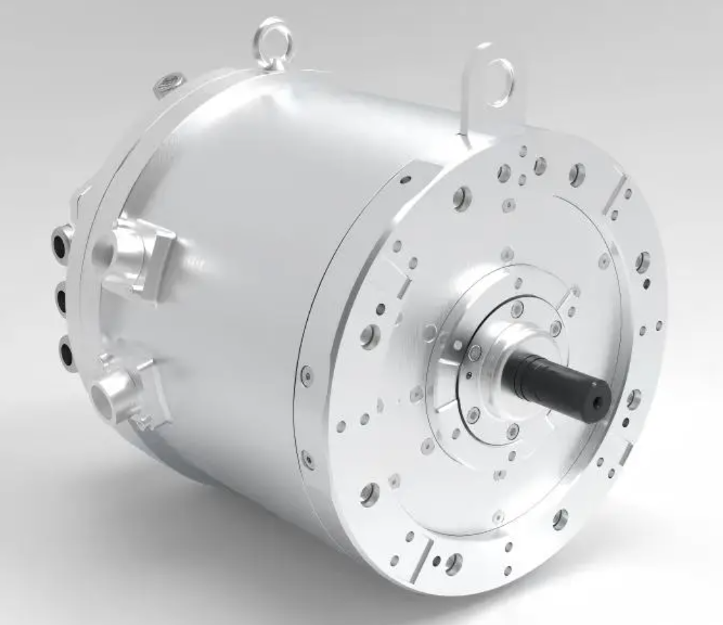
Conventional cooling for a PMSM electric motor usually relies on a water jacket or a spiral water channel embedded in the housing. I found that this approach has a structural limitation: heat must first pass through the housing, stator core, and slot insulation before reaching the coolant. The rotor and permanent-magnet region, which can accumulate heat under high torque, is not directly cooled. The response is therefore delayed, and the cooling effect is indirect. To overcome this limitation, I developed a dual-oil-circuit cooling structure. One oil circuit sprays oil directly onto the stator end windings, and the second oil circuit feeds oil through the rotor shaft, guides it through oil grooves in the magnet-retaining plate, and uses rotor rotation to distribute oil toward the rotor core and permanent magnets. I then integrated a solenoid valve into the rotor oil circuit so that the rotor cooling branch can be opened or closed according to operating conditions. This allows the PMSM electric motor to preserve high cooling capability under severe loads while avoiding unnecessary rotor churning losses under light loads.
The central objective of my work is to improve the thermal management of a PMSM electric motor without sacrificing electric-drive efficiency. I therefore treat the cooling structure and the hydraulic control strategy as one coupled design problem. The stator spray branch directly removes heat from the end windings, where copper loss is concentrated. The rotor slinging branch directly cools the rotor core and permanent magnets, reducing the risk of demagnetization. The solenoid valve acts as an efficiency switch: when the PMSM electric motor operates at low or moderate load, the rotor branch can remain closed; when speed and temperature thresholds are exceeded, the rotor branch opens to provide full dual-circuit cooling. In this way, I balance heat rejection, parasitic loss, and system efficiency.
Motor configuration and modeling basis. I selected an 8-pole, 72-slot flat-wire PMSM electric motor as the study object. The machine uses flat-wire windings and a double-V permanent-magnet arrangement. Flat-wire windings reduce resistance and copper loss, improve slot fill factor, and provide better thermal contact than round-wire windings. The double-V magnet topology increases reluctance torque and flux concentration, but it also creates localized thermal sensitivity in the rotor. The main performance parameters are summarized in Table 1, and the main geometric parameters are listed in Table 2.
| Parameter | Value | Parameter | Value |
|---|---|---|---|
| Rated power | 70 kW | Maximum efficiency | 97% |
| Rated torque | 150 N·m | Maximum torque | 360 N·m |
| Rated speed | 4500 r/min | Maximum speed | 16000 r/min |
| Rated current | 360 A | Pole number | 8 |
| Parameter | Value | Parameter | Value |
|---|---|---|---|
| Core length | 140 mm | Rotor inner diameter | 48 mm |
| Stator slots | 72 | Rotor outer diameter | 144 mm |
| Series turns per phase | 6 | Permanent-magnet width | 3 mm |
| Rotor poles | 8 | Permanent-magnet magnetization length | 10 mm |
Because the PMSM electric motor has periodic symmetry, I used a one-eighth finite-element model to reduce computation. The thermal conduction equation in cylindrical coordinates is written as
$$ \frac{\partial T}{\partial t} = \frac{\lambda}{\rho c}\left(\frac{\partial^2 T}{\partial r^2}+\frac{1}{r}\frac{\partial T}{\partial r}+\frac{1}{r^2}\frac{\partial^2 T}{\partial \theta^2}\right)+\frac{q_v}{\rho c} $$
where \(T\) is temperature, \(t\) is time, \(\lambda\) is thermal conductivity, \(\rho\) is density, \(c\) is specific heat capacity, and \(q_v\) is volumetric heat generation. The boundary conditions I applied are
$$ r=r_1,\quad -k\frac{\partial T}{\partial r}=h(T_w-T_f) $$
$$ \theta=\theta_1,\quad \frac{\partial T}{\partial \theta}=0 $$
$$ \theta=\theta_2,\quad \frac{\partial T}{\partial \theta}=0 $$
Here, \(h\) is the convective heat-transfer coefficient, \(T_w\) is the wall temperature, and \(T_f\) is the fluid temperature. These conditions allow the model to represent convective cooling at the oil-wetted surfaces and symmetry along the periodic boundaries. For the PMSM electric motor, the symmetry assumption is important because it reduces the mesh size while preserving the dominant thermal paths.
Dual oil circuit architecture. My cooling design consists of two hydraulic branches. The first branch supplies oil to spray nozzles located near the stator end windings. The oil impinges directly on the end-winding surface, forming a thin liquid film and carrying heat away by forced convection and partial phase-free cooling. The second branch supplies oil through the rotor shaft. The oil moves radially outward through grooves in the magnet-retaining plate and then exits into the rotor cavity. As the rotor rotates, the oil is slung outward by centrifugal force, creating a distributed cooling film on the rotor inner diameter, rotor core, and magnet surfaces. This dual oil circuit is intended to cool both the main stator heat source and the rotor heat-sensitive region of the PMSM electric motor.
I also incorporated a solenoid valve into the rotor oil circuit. The valve is a normally closed or actively controlled unit that regulates whether oil enters the rotor branch. When the valve is closed, only the stator spray branch operates. When the valve is open, both stator and rotor branches operate. The valve therefore creates a controllable thermal and hydraulic resistance in the rotor branch. The control decision is based on vehicle state, rotor speed, and permanent-magnet temperature. The purpose is to avoid rotor oil churning loss when the PMSM electric motor does not need rotor cooling, while still providing full cooling when temperature or speed thresholds are exceeded.
For finite-element analysis, I simplified the PMSM electric motor by neglecting the housing ribs, small bolts, and assembly gaps that have minor effects on the main thermal path. I smoothed the winding end region and represented the flat-wire bundle as an equivalent solid with orthotropic thermal properties. These simplifications reduce mesh complexity and improve convergence. The assumptions used in the thermal model are listed in Table 3.
| Assumption | Reason |
|---|---|
| Heat generation is uniformly distributed in each component | Reduces local mesh sensitivity while preserving average loss density |
| Assembly gaps are neglected | Contact resistance is represented by equivalent interface properties |
| Thermal radiation is neglected | Oil cooling and conduction dominate below the relevant temperature range |
| Material properties are temperature independent | First-order design evaluation and stable convergence |
| Cooling oil is treated as incompressible | Mach number is very low in the oil circuit |
Loss calculation for the PMSM electric motor. Accurate loss estimation is the foundation of a reliable thermal model. In a PMSM electric motor, losses can be grouped into copper loss, iron loss, mechanical loss, and stray loss. Copper loss is generated by current flowing through the stator winding resistance. Iron loss arises from alternating and pulsating magnetic fields in the stator and rotor cores. Mechanical loss includes bearing loss, windage loss, and other friction effects. Stray loss includes additional eddy-current and harmonic effects that are difficult to calculate analytically.
I calculated iron loss using a loss-separation form. The instantaneous iron-loss density in a lamination can be represented as
$$ dP(t)=\left(\frac{\sigma d_c^2}{12}\left(\frac{dB(t)}{dt}\right)^2+K_h B_m^2 f\right)dV $$
where \(\sigma\) is electrical conductivity, \(d_c\) is lamination thickness, \(B(t)\) is instantaneous magnetic flux density, \(B_m\) is peak flux density, \(K_h\) is the hysteresis-loss coefficient, and \(f\) is frequency. Integrating this expression over volume and time gives the total iron loss. For the PMSM electric motor, the stator teeth and yoke experience the highest alternating flux, while the rotor experiences richer harmonic content because of slotting and inverter excitation.
Copper loss in the flat-wire winding is strongly affected by skin effect and proximity effect, especially at high electrical frequency. I therefore used finite-element simulation to compute the AC copper loss rather than relying only on the DC resistance formula. The DC copper loss is
$$ P_{cu,dc}=m I^2 R_{dc} $$
where \(m\) is the number of phases, \(I\) is RMS current, and \(R_{dc}\) is DC resistance. The AC copper loss is then
$$ P_{cu,ac}=P_{cu,dc}\left(1+k_{ac}\right) $$
where \(k_{ac}\) is the AC loss factor obtained from the finite-element field solution. For a flat-wire PMSM electric motor, this factor can become significant at high speed and high current, so it must be included in the thermal input.
Stray loss is approximated as an equivalent resistance loss:
$$ P_{str}=C_{str}\omega_e^2\left(i_d^2+i_q^2\right)=\frac{3}{2}r_{str}\left(i_d^2+i_q^2\right) $$
$$ r_{str}=\frac{2}{3}C_{str}\omega_e^2 $$
where \(C_{str}\) is the stray-loss coefficient, \(\omega_e\) is electrical angular speed, \(i_d\) and \(i_q\) are d-axis and q-axis currents, and \(r_{str}\) is the equivalent stray-loss resistance. This representation captures the speed-dependent growth of harmonic loss in the PMSM electric motor.
Windage loss is important because the rotor of the PMSM electric motor can reach very high speed. I used the following approximations for cylindrical and end-face windage:
$$ P_{fr}=kC_f\pi\rho\omega^3 r^4 l $$
$$ P_{fend}=\frac{1}{2}C_f\rho\omega^3\left(r_2^5-r_1^5\right) $$
$$ P_f=P_{fr}+P_{fend} $$
where \(P_{fr}\) is cylindrical-surface windage, \(P_{fend}\) is end-face windage, \(k\) is a surface-roughness factor, \(C_f\) is the air-friction coefficient, \(\rho\) is air density, \(\omega\) is angular speed, \(r\) is rotor radius, \(l\) is axial length, and \(r_1\), \(r_2\) are the inner and outer radii of the end face. Although windage does not directly heat the winding, it contributes to total loss and therefore to the efficiency of the PMSM electric motor.
At rated operation, the calculated losses are listed in Table 4. Copper loss dominates the total loss, which confirms that the stator winding is the primary heat source. This is why direct stator end-winding spray cooling is so important for the PMSM electric motor.
| Loss type | Loss value |
|---|---|
| Copper loss | 1279.00 W |
| Iron loss | 368.70 W |
| Mechanical loss | 310.20 W |
| Total estimated loss | 1957.90 W |
I then repeated the loss calculation for low-load, rated-load, and peak-load conditions. The loss distribution changes with operating point. At low load, iron loss and mechanical loss are proportionally larger. At rated and peak load, copper loss becomes dominant. Table 5 summarizes the loss trend used for the thermal simulations.
| Operating condition | Copper loss | Iron loss | Mechanical loss | Total loss |
|---|---|---|---|---|
| Low load | 320 W | 210 W | 150 W | 680 W |
| Rated load | 1279 W | 369 W | 310 W | 1958 W |
| Peak load | 2450 W | 520 W | 390 W | 3360 W |
Oil-circuit boundary conditions and properties. I set the spray flow rate to 8 L/min, the inlet oil temperature to 75 °C, and the outlet pressure to standard atmospheric pressure. These values are representative of an electric-vehicle oil-cooling loop. The oil properties and component material properties are listed in Table 6 and Table 7. I used temperature-independent properties for the initial design because the main purpose was comparative evaluation of the cooling architecture rather than calibration of a detailed production model.
| Spray parameter | Value |
|---|---|
| Oil flow rate | 8 L/min |
| Oil inlet temperature | 75 °C |
| Outlet pressure | Atmospheric pressure |
| Nozzle type | Direct impingement |
| Component | Density (kg/m³) | Specific heat (J/kg·°C) | Thermal conductivity (W/m·°C) |
|---|---|---|---|
| Stator core | 7950 | 450 | 37.5 |
| Rotor core | 7650 | 450 | 37.5 |
| Housing | 2500 | 770 | 190 |
| Flat-wire winding | 8950 | 400 | 395 |
| Shaft | 7850 | 480 | 480 |
| Cooling oil | 803.6 | 2166 | 0.1289 |
| Air region | 1.293 | 1005 | 0.0230 |
The energy equation for the oil-cooled PMSM electric motor is solved in the fluid and solid regions. In the solid region, conduction is governed by
$$ \rho c_p\frac{\partial T}{\partial t}=\nabla\cdot(k\nabla T)+q $$
In the oil region, convection adds an advective term:
$$ \rho c_p\frac{\partial T}{\partial t}+\rho c_p\mathbf{u}\cdot\nabla T=\nabla\cdot(k\nabla T)+q $$
At solid-oil interfaces, I applied a conjugated heat-transfer condition:
$$ -k_s\frac{\partial T_s}{\partial n}=-k_f\frac{\partial T_f}{\partial n}+h\left(T_s-T_f\right) $$
where \(n\) is the surface normal. The convective heat transfer at the spray-cooled stator end winding is approximated by
$$ Q=hA\left(T_s-T_f\right) $$
and the corresponding thermal resistance is
$$ R_{th}=\frac{\Delta T}{Q} $$
These relations allow me to compare the effectiveness of the stator spray branch and the rotor slinging branch. In my thermal network, the stator winding node is coupled to the end-winding oil film, the stator core, the housing, and the air gap. The rotor node is coupled to the permanent magnets, the shaft, the oil film on the rotor inner diameter, and the air gap. The valve-controlled rotor branch changes the convective resistance between the rotor and the oil.
Thermal simulation results at rated operation. Under rated conditions, the PMSM electric motor reaches a stable temperature distribution. The maximum temperature occurs near the middle of the stator, where copper loss and iron loss combine. The highest temperature I obtained was 100.92 °C. The stator end region near the spray nozzle was approximately 89 °C, showing that direct impingement removes a large amount of heat from the end winding. The rotor region remained below 70 °C on average. These results confirm that the dual oil circuit keeps the PMSM electric motor within a safe operating range at rated load. Table 8 lists the rated-condition temperature results.
| Location | Maximum or average temperature |
|---|---|
| Stator middle maximum | 100.92 °C |
| Stator end near spray | 89.00 °C |
| Rotor average | Below 70.00 °C |
| Permanent-magnet region | Below 80.00 °C |
At peak operation, the thermal load increases substantially. The maximum stator temperature rose to 134.6 °C. The directly sprayed stator end region reached approximately 125 °C. The rotor oil-slinging region had an average temperature of about 104 °C. These values are important because the permanent magnets in a PMSM electric motor are sensitive to high temperature. If the magnet temperature exceeds its irreversible-demagnetization threshold, the motor loses torque capability permanently. In my simulation, the rotor cooling branch kept the magnet region below the critical limit even under peak load. Table 9 summarizes the peak-condition temperatures.
| Location | Peak-condition temperature |
|---|---|
| Stator middle maximum | 134.60 °C |
| Stator end near spray | 125.00 °C |
| Rotor oil-slinging average | 104.00 °C |
| Permanent-magnet peak | Below demagnetization limit |
I compared the dual oil circuit with a conventional double-spiral water jacket. The water jacket is a strong baseline, but it cools the PMSM electric motor indirectly through the housing. In my comparison, the oil-cooled structure reduced the rotor maximum temperature by approximately 40 °C. The overall cooling effect improved by more than 30% in the critical stator and rotor regions. This improvement is not only a matter of lower peak temperature; it also reduces thermal cycling, protects insulation, and stabilizes torque output. Table 10 presents the comparison.
| Metric | Water jacket | Dual oil circuit |
|---|---|---|
| Stator temperature control at rated load | Above 100 °C | Below 100 °C |
| Rotor maximum temperature reduction | Baseline | Up to 40 °C lower |
| Cooling-effect improvement | Baseline | More than 30% |
| Direct stator end-winding cooling | No | Yes |
| Direct rotor and magnet cooling | No | Yes |
Solenoid valve control strategy. The rotor slinging branch improves cooling, but it also introduces oil churning and pumping losses. These losses reduce the efficiency of the PMSM electric motor and the electric-drive system. I therefore designed a solenoid valve control strategy that opens the rotor branch only when it is needed. The control strategy uses vehicle state, rotor speed, and permanent-magnet temperature as inputs. The valve command can be written as
$$ S_v=
\begin{cases}
0, & \text{parked}\\
1, & n\le 6000\\
0, & n>6000 \text{ and } T\le 80\\
1, & n>6000 \text{ and } T>80
\end{cases} $$
where \(S_v=1\) means the solenoid valve is open and \(S_v=0\) means it is closed. The speed threshold of 6000 r/min was selected because the measured power loss of the rotor branch rises sharply above this speed. Below 6000 r/min, the additional loss caused by rotor oil slinging is relatively small, so I keep the rotor branch open to maximize cooling. Above 6000 r/min, the rotor branch is opened only when the permanent-magnet temperature exceeds 80 °C. This temperature threshold provides a safety margin for the PMSM electric motor while avoiding unnecessary churning loss.
The control strategy is summarized in Table 11. It is deliberately simple so that it can be implemented in a vehicle controller without a complex optimization solver. The controller only needs the motor speed, the estimated magnet temperature, and the vehicle state. In a production PMSM electric motor, the magnet temperature can be estimated by a thermal observer or measured indirectly through winding temperature and loss models.
| State | Speed condition | Temperature condition | Solenoid valve |
|---|---|---|---|
| Parked | Not applicable | Not applicable | Closed |
| Driving | \(n\le 6000\) r/min | Any | Open |
| Driving | \(n>6000\) r/min | \(T\le 80\) °C | Closed |
| Driving | \(n>6000\) r/min | \(T>80\) °C | Open |
I evaluated the valve strategy by comparing the permanent-magnet temperature with the valve open and closed. The results are shown in Table 12. At low and rated loads, closing the valve did not cause the permanent magnets to exceed the safe limit. At higher loads, however, the temperature difference became significant. For example, at 8000 r/min and 100 N·m, the magnet temperature was 93 °C with the valve open and 103 °C with the valve closed. At 12000 r/min and 50 N·m, the values were 114 °C and 126 °C. These results show that the valve should be open when the PMSM electric motor is thermally stressed, but it can remain closed in lower-risk operating regions to save energy.
| Operating point | Valve open maximum temperature | Valve closed maximum temperature |
|---|---|---|
| 1500 r/min, 30 N·m | 48 °C | 54 °C |
| 4500 r/min, 150 N·m | 67 °C | 76 °C |
| 6000 r/min, 150 N·m | 79 °C | 87 °C |
| 8000 r/min, 100 N·m | 93 °C | 103 °C |
| 10000 r/min, 80 N·m | 102 °C | 111 °C |
| 12000 r/min, 50 N·m | 114 °C | 126 °C |
Experimental validation. I validated the cooling structure and the solenoid valve strategy on a test bench using an 8-pole, 72-slot PMSM electric motor. The motor was cooled by the dual oil circuit, and the ambient temperature was set to 20 °C. I placed thermocouples on the stator end winding and around the rotor permanent magnets. Ten thermocouples were distributed around the magnet circumference at equal angular intervals to capture circumferential temperature variation. The test cycle began with a cold start and continued to a high-speed cruise condition. I measured both temperature rise and electrical power consumption. The power loss of the oil-cooling structure was calculated from the difference between the supplied electrical energy and the mechanical output energy over one cycle.
The experimental results confirmed the simulation trend. With the solenoid valve control strategy, the maximum rotor temperature remained around 110 °C, which is below the critical demagnetization range. Compared with a single-oil-circuit cooling method, the rotor maximum temperature was reduced by approximately 30 °C. Compared with a dual-oil-circuit system that kept the rotor branch fully open at all times, the maximum temperature difference remained within about 10 °C. This means the control strategy does not significantly sacrifice cooling capability. At the same time, it reduces the parasitic power loss caused by rotor oil slinging. Over one driving cycle, the power loss was reduced by approximately 3 kW. This is a meaningful improvement for the overall efficiency of the electric-drive system and for vehicle range.
| Validation metric | Result |
|---|---|
| Rotor maximum temperature with valve strategy | About 110 °C |
| Reduction compared with single oil circuit | About 30 °C |
| Difference compared with always-open dual circuit | Within about 10 °C |
| Power-loss reduction over one cycle | About 3 kW |
| Electric-drive loss reduction | About 20% |
Thermal resistance and efficiency interpretation. To interpret the results more generally, I represented the cooling paths as a thermal network. For any path, the temperature rise is
$$ \Delta T = P_{loss} R_{th} $$
where \(R_{th}\) is the equivalent thermal resistance. The total thermal resistance from winding to oil is composed of conduction resistance through the insulation, convection resistance at the oil-wetted surface, and spreading resistance in the end-winding region:
$$ R_{total}=R_{cond}+R_{conv}+R_{spread} $$
The convection resistance is
$$ R_{conv}=\frac{1}{hA} $$
The oil flow rate affects \(h\). In general, increasing flow rate increases \(h\) and reduces \(R_{conv}\), but it also increases pump loss. I therefore treat the oil flow rate as a design variable that must be optimized together with the valve strategy. The pump power can be approximated as
$$ P_{pump}=\frac{\Delta p Q_v}{\eta_p} $$
where \(\Delta p\) is pressure drop, \(Q_v\) is volumetric flow rate, and \(\eta_p\) is pump efficiency. The net benefit of the cooling system is therefore a trade-off between reduced motor loss and increased pump and churning loss. In my design, the solenoid valve reduces the rotor-branch flow when cooling demand is low, which lowers \(\Delta p\) and \(P_{pump}\).
The efficiency of the electric drive can be expressed as
$$ \eta_{drive}=\frac{P_{out}}{P_{out}+P_{loss,total}} $$
where \(P_{out}\) is mechanical output power and \(P_{loss,total}\) includes motor electromagnetic loss, rotor oil churning loss, and pump loss. My results show that the valve-controlled dual oil circuit reduces \(P_{loss,total}\) by approximately 20% compared with an uncontrolled high-loss cooling configuration. This gain is important because the PMSM electric motor operates over a wide speed range, and small efficiency improvements accumulate over a full driving cycle.
Design sensitivity and operating maps. I also examined how the cooling performance changes with speed, torque, oil flow, and oil temperature. The highest temperatures occur in the stator middle and the end-winding region. The rotor temperature depends strongly on the rotor oil branch. When the valve is closed, the rotor temperature rises faster with load. When the valve is open, the rotor temperature is suppressed, but the rotor churning loss increases. The control map therefore has two regions: a low-loss region where the valve can remain closed, and a high-cooling region where the valve must open. Table 13 presents a simplified operating map based on my simulation and test results.
| Speed region | Torque region | Rotor cooling need | Valve action |
|---|---|---|---|
| Low speed | Low torque | Low | Closed or open with negligible loss |
| Low speed | High torque | Moderate to high | Open |
| High speed | Low torque | Moderate due to frequency and windage | Open above temperature threshold |
| High speed | High torque | High | Open |
| Parked or charging | Not applicable | Low | Closed |
The oil flow rate also affects the temperature distribution. I found that increasing the stator spray flow rate lowers the end-winding temperature quickly, but the benefit saturates because the thermal resistance shifts to insulation and slot conduction. Increasing the rotor flow rate lowers the magnet temperature, but the churning loss grows with speed. This is why a speed-dependent valve strategy is more effective than simply increasing the total oil flow. In my design, the PMSM electric motor receives high cooling only when it needs it.
Comparison with conventional water cooling. Conventional water-jacket cooling is mature and effective for housing-level heat rejection. However, for a high-torque-density PMSM electric motor, the heat path from the stator end winding and rotor magnet to the housing is long. The water jacket cannot directly cool the end winding, and it cannot cool the rotor magnets at all. My dual oil circuit changes the thermal boundary conditions at the source. The stator spray branch removes heat directly from the end winding, and the rotor slinging branch removes heat directly from the rotor. This is why the temperature reduction is large even when the total cooling power is comparable. Table 14 summarizes the physical differences.
| Feature | Water jacket | Dual oil circuit with solenoid valve |
|---|---|---|
| Primary heat path | Winding to core to housing to water | Winding to oil and rotor to oil |
| Stator end-winding cooling | Indirect | Direct spray |
| Rotor magnet cooling | Poor | Direct slinging |
| Response to transient load | Delayed | Fast |
| Parasitic loss control | Pump loss only | Valve-controlled rotor branch |
| Demagnetization risk | Higher under peak torque | Lower |
Mechanical and hydraulic integration. The solenoid valve must be integrated into the rotor oil circuit without creating excessive pressure drop or leakage. I placed the valve in the stationary oil supply path before the rotary union. This avoids adding mass to the rotor and simplifies electrical connection. The valve opens and closes according to the control signal, and the rotor branch then receives oil through the shaft. The rotary union must handle the oil pressure and speed. In my design, the rotor oil path is symmetric to avoid unbalanced hydraulic forces. The grooves in the retaining plate are sized to deliver the required flow without excessive local pressure loss. The valve is normally closed when the vehicle is parked, which also reduces static leakage and prevents unnecessary oil accumulation in the rotor cavity.
The stator spray nozzles are arranged around the end winding in a pattern that avoids direct impingement on insulation weak points. The spray angle and distance are selected so that the oil film covers the end-winding surface without excessive splash loss. Because the PMSM electric motor may rotate in both directions, the rotor slinging path is designed to be directionally tolerant. Centrifugal force dominates the distribution, so the cooling effect is maintained in both forward and reverse operation.
Thermal safety and demagnetization margin. Permanent-magnet demagnetization is one of the most serious failure modes in a PMSM electric motor. The risk increases with magnet temperature and opposing magnetic field. My rotor cooling branch reduces the magnet temperature, which directly increases the demagnetization margin. I define a simple margin index:
$$ M_d=T_{d,limit}-T_{mag,max} $$
where \(T_{d,limit}\) is the demagnetization-limit temperature and \(T_{mag,max}\) is the maximum magnet temperature. A larger \(M_d\) means a safer design. With the valve-controlled dual oil circuit, \(M_d\) remains positive even under peak torque and high-speed operation. With a conventional water jacket, the margin can become small or negative under repeated high-torque events. This is a key reason I consider direct rotor cooling essential for a high-performance PMSM electric motor.
Insulation life and thermal cycling. The stator end winding is also sensitive to thermal cycling. Repeated heating and cooling can degrade insulation and reduce lifetime. Direct oil spray reduces the peak end-winding temperature and smooths the transient temperature rise. The lower peak temperature slows insulation aging. The oil also provides some dielectric protection, although the insulation system must be compatible with the oil. In my design, the flat-wire winding surface is smooth, which improves oil coverage and reduces local hot spots. The oil flow also reduces the temperature difference between the end winding and the slot region, lowering mechanical stress caused by differential thermal expansion.
Control implementation details. The solenoid valve control can be implemented as a state machine. The inputs are vehicle state \(V\), rotor speed \(n\), and magnet temperature \(T_{mag}\). The output is valve command \(S_v\). The logic is
$$ S_v =
\begin{cases}
0, & V=\text{parked}\\
1, & V=\text{driving and } n\le 6000\\
0, & V=\text{driving and } n>6000 \text{ and } T_{mag}\le 80\\
1, & V=\text{driving and } n>6000 \text{ and } T_{mag}>80
\end{cases} $$
To avoid chattering around the thresholds, I add hysteresis. For example, the valve opens at 80 °C and closes at 75 °C. Similarly, the speed threshold can have a small hysteresis band. This prevents rapid valve cycling and improves durability. The controller can also use a feedforward term based on torque and speed to anticipate temperature rise. If the vehicle requests a high-torque acceleration, the valve can open before the magnet temperature reaches the threshold. This predictive action improves transient thermal safety.
Loss reduction and range benefit. The electric-drive loss reduction achieved by the valve strategy is approximately 20%. In an electric vehicle, a 20% reduction in drive-system cooling-related loss can translate into a measurable range increase, especially in urban driving with frequent starts and stops. The PMSM electric motor spends much of its time at part load, where the rotor branch is not always needed. By closing the valve in those periods, the system avoids unnecessary oil churning. The valve opens during high-load or high-temperature periods, when cooling is more valuable than the small efficiency penalty. This conditional operation is the core advantage of the integrated design.
Model limitations and next steps. My model uses temperature-independent material properties and simplified winding geometry. In a production design, temperature-dependent viscosity and thermal conductivity of the oil should be included. The contact resistance between the flat-wire winding and the slot liner should be calibrated with tests. The rotor oil distribution should be validated with high-speed visualization or CFD. The solenoid valve should be tested for durability and response time. In future work, I would couple the thermal model with a real-time observer for magnet temperature and implement a model predictive control strategy for the valve. I would also optimize the nozzle position, oil groove geometry, and valve threshold using multi-objective optimization. The objective would be to minimize peak temperature and total drive loss while satisfying demagnetization margin and insulation limits.
Key quantitative outcomes. The most important results from my study are summarized in Table 15. The dual oil circuit with a solenoid valve keeps the stator below 100 °C at rated operation, improves cooling by more than 30% compared with a conventional water jacket, reduces the rotor maximum temperature by up to 40 °C, and lowers electric-drive loss by approximately 20%. The valve-controlled rotor branch maintains rotor temperature within about 10 °C of an always-open dual circuit while saving about 3 kW of loss over a test cycle. These outcomes show that the design is both thermally effective and energetically efficient for a PMSM electric motor.
| Outcome | Value |
|---|---|
| Rated stator maximum temperature | Below 100 °C |
| Stator end-winding temperature at rated load | About 89 °C |
| Cooling improvement over water jacket | More than 30% |
| Rotor maximum temperature reduction | Up to 40 °C |
| Peak stator maximum temperature | About 134.6 °C |
| Peak rotor oil-slinging average temperature | About 104 °C |
| Electric-drive loss reduction | About 20% |
| Cycle power-loss reduction | About 3 kW |
Conclusion. I designed a dual-oil-circuit thermal-management structure for a flat-wire oil-cooled PMSM electric motor and integrated a solenoid valve into the rotor branch. The stator end-winding spray branch directly cools the main copper-loss region, and the rotor slinging branch directly cools the rotor core and permanent magnets. The solenoid valve controls the rotor branch according to vehicle state, speed, and magnet temperature. Through loss calculation, finite-element thermal simulation, and experimental validation, I found that the proposed structure significantly improves cooling performance and reduces the risk of overheating and demagnetization. The PMSM electric motor remains below 100 °C at rated operation, and the peak temperature is controlled within a safe range. The valve-controlled dual oil circuit also reduces electric-drive loss by approximately 20%, demonstrating that thermal management and efficiency can be improved together. This integrated approach provides a practical path for high-performance, high-efficiency PMSM electric motor thermal design in electric vehicles.