
A new case study on a severe cell imbalance fault in a power battery pack has outlined a practical, workshop-ready method for identifying the root cause without unnecessary pack disassembly, quantifying the boundary between repair and replacement, and verifying the repair through charge-discharge cycling and road testing. The work focuses on a vehicle that triggered fault code P1AC400, a condition associated with power battery cell imbalance that can reduce driving range, disrupt charging, and, in severe cases, contribute to thermal runaway risk.
The case study reports that the power battery pack showed a maximum cell voltage difference of 234 mV. Using a 5 min non-disassembly positioning method, the investigation locked cell #101 as the source of the fault. Subsequent precision testing measured an internal resistance of 26.3 mΩ for cell #101, a capacity deviation of 15%, and a module voltage difference of 234 mV. On the basis of those measurements, the fault was classified as a moderate imbalance fault at the pack level, while the individual cell displayed severe degradation characteristics. The vehicle’s state of health was only 61%, indicating that the power battery pack as a whole already had a low health level and that balancing alone would not be sufficient to restore reliable performance.
The research describes a two-level diagnostic process built around “rapid positioning plus precise verification.” The first level uses the battery management system, or BMS, and diagnostic equipment to read fault codes, cell voltages, state of charge, state of health, balancing duration, and module voltage differences. The second level uses direct measurement of cell parameters after safe pack disassembly when the fault level requires it. The resulting maintenance scheme combines graded balancing repair, cell or module replacement, and BMS calibration. After a full charge-discharge cycle and a 100 km road test, the power battery pack voltage difference remained stably below 50 mV and the fault was eliminated. The case study concludes that the graded treatment scheme is effective and can provide a theoretical basis and practical reference for power battery fault diagnosis, on-site repair, and routine operation and maintenance. It also identifies the work as technical support for high-skilled talent cultivation and industry-education integration in the new energy battery materials industry innovation network in Guizhou.
1. A Field Fault Exposes the Cost of Power Battery Cell Imbalance
The case study begins with a market reality that is familiar to service engineers and fleet operators: cell imbalance is one of the most common failure modes in a power battery pack. Industry statistics cited in the study indicate that cell imbalance accounts for more than 40% of power battery faults. The consequences range from reduced driving range and abnormal charging to power limitation, high-voltage protection, and even safety incidents. For a power battery pack, even a small inconsistency in voltage, internal resistance, capacity, or self-discharge rate can grow over time and undermine the performance of the entire pack.
The vehicle in the case study provided a clear example of how a power battery fault can present in stages. The fault code P1AC400 was active, and the BMS data showed a pack voltage difference of 234 mV. The 5 min non-disassembly positioning method allowed the technician to identify the highest and lowest cell numbers and the module to which they belonged, compare balancing duration, and confirm the fault source without opening the pack. Cell #101 stood out. Its balancing compensation was clearly insufficient, and the passive balancing function could not compensate for the capacity decay difference. The measured internal resistance of 26.3 mΩ and capacity deviation of 15% confirmed that the cell had moved beyond a simple balancing problem.
The study uses a fault classification framework that links voltage difference thresholds to inspection and repair actions. The framework is important because it gives service teams a common language for deciding when a power battery pack can be balanced, when it must be unpacked for inspection, and when a cell or module must be replaced. The classification criteria are summarized in the accompanying table.
| Fault level | Voltage difference threshold | Manifestation | Treatment |
|---|---|---|---|
| Normal | ≤50 mV | BMS balancing controllable | No treatment required |
| Mild | 50–200 mV | Important parameter values abnormal | Balancing repair required |
| Moderate | 200–300 mV | Internal resistance and capacity show obvious degradation | Unpacking inspection or replacement required |
| Severe | >300 mV | Irreversible cell degradation | Module or cell replacement required |
The case study places the P1AC400 vehicle in the moderate range because the pack voltage difference was 234 mV. At the same time, the individual cell data showed that cell #101 had an internal resistance of 26.3 mΩ and a capacity deviation of 15%, which placed the cell itself in a severely degraded condition. The distinction matters for a power battery repair strategy. A pack-level classification may point to unpacking inspection and replacement, while cell-level measurements determine whether the correct action is targeted cell replacement, module replacement, or a broader pack-level intervention.
The study also describes how imbalance manifests at different severity levels. Mild imbalance may appear as a gradual decline in range, slightly slower charging, and no dashboard warning; only BMS background data reveal that the cell voltage difference has exceeded the standard. Moderate imbalance can reduce range by more than 10%, cause charging interruptions, occasionally trigger power limitation, illuminate the battery fault lamp, and produce slight heating in some modules. Severe imbalance can cause a sharp reduction in range, slow charging or even failure to charge, frequent power limitation protection, cell swelling, leakage, odor, and in serious cases an inability to start the high-voltage system. These staged symptoms reinforce the need for early power battery data monitoring and a diagnostic process that does not wait for a severe fault to appear.
2. Root Causes Range From Manufacturing Tolerance to BMS Balancing Failure
The case study identifies multiple, coupled causes of power battery cell imbalance. The first is the inherent consistency difference among cells. Even cells of the same batch and specification can show initial capacity, internal resistance, and self-discharge rate deviations of approximately ±2% because of raw material purity, electrode coating, and packaging process limits. In the early stage, the effect is weak. As charge-discharge cycles accumulate, the parameter deviation gradually expands and eventually becomes a power battery cell imbalance fault.
The second cause is differentiated cell degradation. Long-term fast charging, deep low-state-of-charge driving, and long-term full-charge parking increase the cycle load on cells. The temperature field inside a power battery pack is not uniform, and cells near a heat source or in a poorly cooled area degrade faster. Their internal resistance rises and their capacity fades more quickly, widening the performance gap between cells. This is a critical point for power battery maintenance because a pack-level average can hide a local problem that is already severe.
The third cause is failure of the BMS balancing function. The BMS is the core control unit for maintaining cell consistency, and it can use passive balancing or active balancing. Damage to balancing resistors, soldering defects or virtual welding in metal-oxide-semiconductor, or MOS, components, damage to capacitors and inductors in an active balancing module, and abnormal balancing strategy logic can all cause balancing compensation to fail. In the case study, most cells had accumulated more than 2,100 h of balancing, while the abnormal cell #101 had clearly insufficient balancing compensation. Passive balancing could no longer compensate for the capacity decay difference, making it a core cause of the fault.
The fourth cause is abnormal connection and sampling. Loose module connection bar bolts, oxidized wiring harnesses, and virtual welding in flexible printed circuit, or FPC, boards increase contact resistance and cause uneven current distribution. Degraded voltage sampling harnesses and inaccurate sensors can distort BMS data, preventing the system from accurately identifying an abnormal cell and missing the early window for balancing repair. For a power battery pack, data integrity is as important as electrical integrity.
The fifth cause is an uneven temperature field in the power battery pack. The optimal operating temperature for a power battery pack is 20–35 °C. Blocked thermal management pipes, failed cooling fans, and failed heating components can create local high or low temperatures in a module, accelerate cell degradation, and induce cell consistency imbalance. The case study treats thermal management as part of the root-cause analysis rather than a secondary maintenance item.
- Inherent cell consistency differences can begin at approximately ±2% and widen with cycling.
- Fast charging, deep discharge, and long full-charge parking accelerate differentiated degradation.
- Balancing resistor, MOS component, active balancing module, and strategy faults can disable BMS compensation.
- Loose connections, oxidized harnesses, FPC virtual welding, and sampling errors can hide or worsen imbalance.
- Uneven temperature distribution can accelerate local cell aging and undermine power battery consistency.
The case study’s root-cause analysis supports a key conclusion for power battery service: cell imbalance is rarely the result of a single factor. Manufacturing tolerance, user behavior, BMS balancing capability, connection quality, sampling accuracy, and thermal management interact. A repair that addresses only the voltage difference without verifying the cell condition and the BMS calibration is likely to produce a short-term improvement and a recurring fault.
3. A Two-Level Diagnostic Process Built for Workshop Reality
The study compares traditional and emerging detection methods and then selects a practical combination for engineering work. The traditional BMS data reading method connects a dedicated diagnostic instrument to the vehicle’s on-board diagnostics, or OBD, interface and reads fault codes, cell voltages, state of charge, state of health, balancing duration, and module voltage difference. It does not require pack disassembly and can quickly determine the fault type and the location of an abnormal cell. In the case study, this rapid positioning method confirmed the valid P1AC400 fault code, ruled out communication faults, locked the highest and lowest cell numbers and their module, compared cumulative balancing time to distinguish insufficient balancing from cell degradation, and verified the fault source through module voltage difference.
The direct cell parameter measurement method is suited to precise verification of moderate and severe cell imbalance. It follows high-voltage safety rules: power down, disconnect the maintenance switch, and wait 10 min to release residual high voltage; then disassemble the power battery pack and use a high-precision multimeter, internal resistance tester, and capacity tester to measure cell parameters. For lithium iron phosphate cells, the study uses a normal internal resistance of less than 10 mΩ, a pack voltage difference of less than 50 mV, and a capacity deviation of less than 5% as reference criteria. The measured internal resistance of cell #101 was 26.3 mΩ and the capacity deviation was 15%, which confirmed severe degradation.
The charge-discharge curve analysis method uses a full charge and full discharge test to plot cell voltage curves. A normal voltage curve is smooth and continuous. When cell imbalance is present, the charging plateau rises sharply and the discharging plateau drops sharply, which provides an intuitive assessment of power battery pack consistency. The method is time-consuming and is mainly suitable for laboratory and professional inspection scenarios. Emerging methods include machine learning detection, using K-means, OPTICS clustering, and 1DCNN-LSTM algorithms with voltage, current, temperature, and state of charge as feature data to train models for early warning of hidden faults and accurate identification of abnormal cells. Multi-sensor fusion detection combines voltage, current, temperature, and vibration sensor data to avoid single-sensor errors and identify temperature unevenness and loose connections. Those methods offer strong predictive and comprehensive detection capabilities, but they require large data sets, complex sensor layouts, and higher implementation costs.
The study’s comparison concludes that BMS data reading is convenient and efficient for initial screening; direct cell measurement offers the highest accuracy and is suitable for disassembly verification; charge-discharge curve analysis is suitable for performance evaluation; and machine learning and sensor fusion are suitable for intelligent early warning and high-end application scenarios. For engineering practice, the optimal combination is BMS rapid screening plus disassembly measurement verification. This combination is particularly relevant for a power battery pack that has already set a fault code, because it balances speed, cost, and diagnostic confidence.
The diagnostic logic follows a complete chain: fault code initial judgment, BMS data screening, voltage difference graded judgment, actual measurement precise verification, graded maintenance, calibration verification, and long-term operation and maintenance. The first step reads the P1AC400 fault code and uses BMS background data to quickly lock the highest and lowest cells and their module, completing an initial location without unpacking. The next step divides the fault level according to the cell voltage difference threshold. Mild imbalance can be restored through constant-temperature professional balancing repair. Moderate and severe imbalance require strict high-voltage safety procedures, pack disassembly, and internal resistance, capacity, and appearance measurements to determine whether a cell has irreversible degradation.
For cells without irreversible degradation, the focus is on inspecting voltage sampling harnesses, FPC circuits, and the BMS balancing circuit, rewriting the balancing strategy, and conducting a static rest recheck. For degraded cells with capacity fade and excessive internal resistance, the method calls for replacement with cells of the same batch and parameters or replacement of the entire module. During assembly, contact surfaces must be cleaned and conductive protection must be applied. After repair, BMS parameter entry, state of charge and state of health reset, and full charge-discharge self-learning calibration must be completed. Verification includes static rest, charge-discharge cycling, and a real vehicle road test to confirm that the fault does not recur and that the cell voltage difference remains within the standard range. Finally, a long-term mechanism of regular data monitoring, optimized charging habits, and thermal management maintenance is established to slow cell degradation and reduce the probability of recurrence.
4. Graded Repair Defines the Boundary Between Repair and Replacement
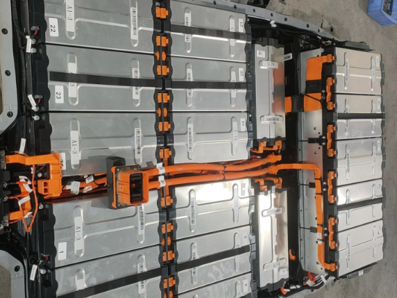
The case study’s repair preparation is shaped by safety, tooling, and data requirements. On the safety side, insulated gloves, insulated shoes, and protective goggles are required, and the power-down, maintenance switch disconnection, and capacitor discharge procedures must be strictly followed. On the tooling side, high-precision testing instruments, a balancer, an original diagnostic instrument, welding tools, and spare cells or modules of the same batch are prepared. On the data side, the original fault code, cell voltages, state of health, balancing duration, and other data are retained to support the repair plan. These steps are especially important for a high-voltage power battery pack, where a procedural error can create both safety and quality risks.
The graded repair scheme separates mild degradation from severe degradation. The mild degradation scheme applies when cell internal resistance is ≤20 mΩ, capacity deviation is ≤10%, and there is no swelling, leakage, or damage. The power battery pack is placed in a 25 °C constant-temperature environment, and a high-precision balancer is used to charge low-voltage cells and discharge high-voltage cells until the pack voltage difference is below 50 mV. The diagnostic instrument is then used to reset the BMS balancing strategy, enable static balancing mode, and leave the pack at full charge for 24 h. Multiple rounds of full-charge rest and deep discharge verification are performed, and a 50 km road test without a recurring fault code is considered acceptable.
The severe cell degradation replacement scheme applies when measured internal resistance is >20 mΩ, or the deviation from the module mean is >50%, or measured capacity deviation is >10%, or there is swelling, leakage, or damage. A new cell of the same model and batch is selected, with a voltage difference of <20 mV, an internal resistance difference of <1 mΩ, and a capacity deviation of <3%. If multiple cells in a module are degraded, the entire M10 module is replaced. During assembly, the connection bar is cleaned and conductive paste is applied to ensure reliable contact. For the vehicle type in the case study, BMS parameter entry, state of charge and state of health reset, and full charge-discharge self-learning calibration must be completed. Verification includes static rest, fast and slow charging cycles, and a 100 km road test to confirm stable voltage difference and no fault alarm.
In the actual case, cell #101 had an internal resistance of 26.3 mΩ and a capacity deviation of 15%, which reached the replacement threshold. The selected solution was replacement of the cell in the M10 module. The study also addresses BMS balancing circuit repair. If the fault is traced to a damaged balancing resistor, MOS component, or active balancing module, the same specification component is replaced and virtual welding points are repaired. The balancing control strategy is rewritten, and after a 24 h full-charge rest, the cell voltage difference is rechecked to confirm that balancing control has been restored.
- Mild degradation: internal resistance ≤20 mΩ, capacity deviation ≤10%, no swelling or leakage, balancing repair and BMS reset.
- Severe degradation: internal resistance >20 mΩ, module mean deviation >50%, capacity deviation >10%, or visible damage, cell or module replacement.
- Replacement cell matching: voltage difference <20 mV, internal resistance difference <1 mΩ, capacity deviation <3%.
- Post-repair calibration: BMS parameter entry, state of charge and state of health reset, full charge-discharge self-learning.
- Verification: static rest, fast and slow charging cycles, and a 100 km road test.
The study’s decision logic is notable because it moves the power battery repair decision away from subjective judgment. The 200 mV voltage difference is treated as a critical point for unpacking inspection, which reduces unnecessary disassembly. The combination of internal resistance and capacity deviation provides a quantifiable boundary for irreversible cell degradation. In the conclusion, the study identifies an internal resistance above 20 mΩ together with a capacity deviation above 15% as the threshold for irreversible cell degradation. The repair protocol itself uses an internal resistance above 20 mΩ, a capacity deviation above 10%, or visible damage as replacement triggers. This layered approach allows a service team to distinguish between a pack that can be recovered through balancing and a pack that requires cell or module replacement.
5. Verification Shows Power Battery Voltage Difference Stabilized Below 50 mV
After repair, the power battery pack was subjected to a full charge-discharge cycle and a 100 km road test. The fault was eliminated, no fault code appeared, and the key parameters improved substantially. The maximum cell voltage difference fell from 234 mV to 45 mV, a reduction of 80.8%, and the result was judged qualified against the <50 mV criterion. The internal resistance of cell #101 fell from 26.3 mΩ to 8.7 mΩ, a reduction of 66.9%, and the result was judged qualified against the <10 mΩ criterion. The power battery pack state of health rose from 61% to 92%, an increase of 31%, indicating a significant recovery in health. Capacity deviation fell from 15% to 4%, a reduction of 11 percentage points, and the result was within the normal <5% criterion.
| Key parameter | Before repair | After repair | Change | Result judgment |
|---|---|---|---|---|
| Maximum cell voltage difference | 234 mV | 45 mV | 80.8% reduction | Qualified, <50 mV |
| Internal resistance of cell #101 | 26.3 mΩ | 8.7 mΩ | 66.9% reduction | Qualified, <10 mΩ |
| Power battery pack state of health | 61% | 92% | 31% increase | Significant health recovery |
| Capacity deviation | 15% | 4% | 11 percentage point reduction | Normal, <5% |
The comparison confirms that precise replacement of the degraded cell or module, followed by BMS calibration, can clear the imbalance fault and restore the power battery pack to a stable operating condition. The voltage difference convergence rate of 80.8% is a useful indicator for service quality because it shows how far the pack moved from the fault threshold toward the normal range. The case study treats the result as evidence of the effectiveness of the graded treatment scheme and as a standardized work procedure for after-sales repair.
The verification also highlights why BMS calibration cannot be treated as an optional step. The vehicle type in the case study has strict BMS control over voltage difference. Without a full charge-discharge calibration after repair, the system may repeatedly trigger the P1AC400 fault code even when the physical repair has been completed. For a power battery pack, the BMS is not only a monitoring device; it is also the control layer that defines how the pack is balanced, how state of charge is estimated, and how state of health is reported. Repairing the hardware without recalibrating the control layer leaves the power battery system in an inconsistent state.
6. Long-Term Maintenance and Key Warnings for High-Degradation Power Battery Packs
The study recommends a long-term maintenance strategy that addresses user behavior, data monitoring, and thermal management. Charging habits should be optimized by reducing long-term fast charging and ensuring at least one slow full charge and rest each month to support the BMS static balancing effect. Battery data should be read every 5,000 km to monitor cell voltage difference and state of health changes, so that early detection and early intervention are possible. The power battery pack thermal management system should be checked regularly to ensure smooth heat dissipation and a uniform module temperature field, which helps slow cell degradation.
The case study also provides key reminders for real vehicle repair. The vehicle’s state of health was only 61%, which indicates obvious overall attenuation of the power battery pack. Balancing alone could not cure the fault because cell #101 had already suffered irreversible capacity degradation, and a balancing-only repair would be prone to short-term recurrence. The vehicle’s BMS has strict voltage difference control, so a full charge-discharge cycle calibration must be completed after repair; otherwise, the P1AC400 fault code may be triggered again. These reminders are directly relevant to power battery service practice because they connect the physical condition of the pack with the control behavior of the BMS.
- Reduce long-term fast charging and use a monthly slow full charge with rest to support static balancing.
- Read power battery data every 5,000 km and track cell voltage difference and state of health trends.
- Maintain the thermal management system to keep module temperatures uniform and heat dissipation effective.
- Do not rely on balancing alone when a cell has irreversible capacity degradation.
- Complete full charge-discharge calibration after repair when the BMS has strict voltage difference control.
The maintenance strategy reflects a shift from reactive repair to lifecycle management. A power battery pack does not fail in a single moment; its consistency degrades through repeated cycles, temperature exposure, charging habits, and control errors. Regular data monitoring can reveal a rising voltage difference before it becomes a fault code. Thermal management can reduce the local conditions that accelerate cell aging. Charging behavior can reduce the load imbalance that drives differentiated degradation. When these measures are combined with a clear diagnostic and repair standard, the power battery pack can remain in service longer and with lower safety risk.
7. Implications for Industry, Training, and the Power Battery Supply Chain
The case study’s significance extends beyond a single repair. It provides a standardized workflow for power battery fault diagnosis and maintenance that can be used in after-sales service, fleet maintenance, and vocational training. The two-level process of rapid positioning and precise verification gives technicians a repeatable method for moving from a fault code to a measured root cause. The graded repair scheme gives service managers a quantifiable basis for deciding between balancing, cell replacement, module replacement, and BMS calibration. The verification protocol gives quality control teams a way to confirm that the power battery pack has returned to a stable condition.
The study also connects technical work with talent development. It identifies the work as a practical carrier for industry-education integration in the new energy battery materials industry innovation network in Guizhou and as support for high-skilled talent cultivation in the power battery maintenance field. That connection is important because the power battery supply chain needs not only materials researchers and cell manufacturers but also service technicians who can diagnose and repair complex pack-level faults. A vocational training program that uses real fault cases, measured data, and standardized repair procedures can prepare students for the actual conditions they will encounter in the field.
For the power battery industry, the case study reinforces the value of data-driven service. The BMS already collects cell voltages, temperatures, balancing duration, state of charge, and state of health. When that data is read systematically, it can shorten diagnosis time and reduce unnecessary disassembly. When it is combined with direct measurements, it can distinguish a balancing problem from a degraded cell. When it is used after repair, it can verify that the power battery pack has stabilized. This data chain is the foundation for safer and more cost-effective power battery maintenance.
The study also has implications for warranty and repair economics. A power battery pack is a high-value component, and unnecessary module replacement can be costly. A repair strategy that first uses BMS data to locate the fault, then uses direct measurement to verify the cell condition, and then applies a graded repair decision can avoid premature replacement while still addressing severe degradation. At the same time, the study warns against over-confidence in balancing. When a cell has irreversible capacity degradation, repeated balancing may only delay the inevitable and may increase the risk of recurrence. The boundary between repair and replacement must be based on measured parameters, not on the appearance of a temporary voltage improvement.
8. Conclusion and Outlook for Power Battery Imbalance Diagnosis
The case study concludes that power battery cell imbalance is caused by a coupling of inherent consistency differences, cell degradation, BMS balancing failure, connection and sampling abnormalities, and uneven temperature fields. It is a typical fault that cannot be ignored in new energy vehicles. Using the P1AC400 field case, the study proposes a two-level inspection process of rapid positioning plus disassembly-based precise verification. It identifies a 200 mV voltage difference as the critical point for unpacking inspection, which greatly reduces blind disassembly. It quantifies the boundary between repair and replacement and identifies an internal resistance above 20 mΩ together with a capacity deviation above 15% as the threshold for irreversible cell degradation, addressing the problem of subjective repair decisions.
The study verifies the effectiveness of a scheme based on replacing the aged cell and performing full charge-discharge BMS calibration. The power battery pack voltage difference convergence rate reached 80.8%, and the repair procedure provides a standardized work process for after-sales service. The work can serve as a practical carrier for industry-education integration and high-skilled talent cultivation in the new energy battery materials industry innovation network in Guizhou, supporting the development of technicians who can handle power battery diagnosis and repair.
The study outlines four development trends for power battery imbalance detection and repair. The first is intelligent detection, using vehicle connectivity big data and artificial intelligence algorithms for real-time fault monitoring and early prediction. The second is efficient balancing, with active balancing gradually replacing passive balancing to shorten balancing time and improve repair results. The third is standardized repair, with unified fault classification, inspection, and repair specifications and wider use of modular replacement. The fourth is full-lifecycle operation and maintenance, using battery health management systems to monitor and maintain the power battery pack from production through service to end-of-life.
The study also notes that as solid-state batteries and sodium-ion batteries move toward industrial application, the mechanisms of cell imbalance and the associated repair technologies will become important research topics. The diagnostic and repair processes will need to be adapted to new power battery systems. For the power battery sector, the case study offers a clear message: accurate diagnosis, measured decision-making, and calibrated repair can turn a severe imbalance fault into a controlled service event, improve safety, extend service life, and reduce maintenance cost. The power battery pack remains a complex high-voltage system, but the combination of BMS data, precision measurement, graded repair, and verification creates a practical path for reliable maintenance.