
I designed this dual-mode automatic detection circuit to solve a practical problem I have observed in electric vehicle charging maintenance: the low-voltage communication behavior and the high-voltage output behavior of an AC electric vehicle charging system are tightly coupled in time, yet they are difficult to separate with conventional tools. A technician often knows that electric vehicle charging has failed, but does not know whether the failure belongs to the charging pile, the charging gun, the vehicle inlet, the vehicle control pilot loop, the connection confirmation loop, the onboard charger, or the AC output contactor. My objective was to create a compact STM32-based tester that can automatically simulate either the vehicle side or the charging-pile side, collect the relevant CC and CP signals, and localize faults without requiring an oscilloscope or a logic analyzer.
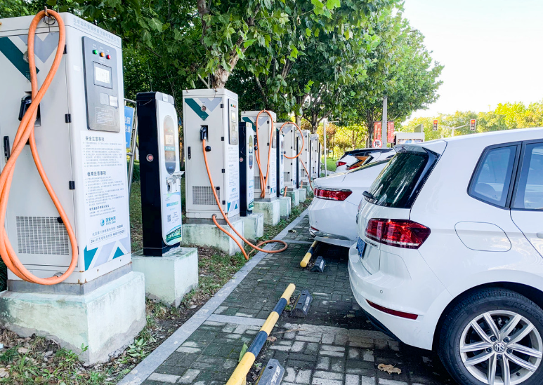
The design is intended for electric vehicle charging service bays, charger production lines, and embedded self-test functions inside AC charging equipment. It uses two operating modes. In the first mode, the tester behaves like a vehicle and inspects a charging gun or charging pile. In the second mode, the tester behaves like a charging pile and inspects a vehicle. A relay matrix performs mode selection and electrical interlocking. The STM32 acquires conditioned signals, executes a state-machine diagnosis, and reports fault codes through a simple human-machine interface. In my bench and vehicle tests, the circuit identified the injected faults with accuracy above 99 percent and reduced the average diagnosis time by about 90 percent compared with a manual oscilloscope-based procedure.
1. Motivation and Design Requirements
AC electric vehicle charging is not simply a power connection. It is a sequenced interaction between the charging equipment and the vehicle. The vehicle must confirm that a plug is inserted, the charging equipment must confirm that the vehicle is connected, the equipment must announce its available current capacity, the vehicle must indicate that it is ready, and only then may the AC contactor close. Because the sequence is interlocked, a single defective resistor, a stuck switch, a broken pilot wire, or a damaged latch can stop the entire electric vehicle charging process before any high voltage appears. This makes fault isolation difficult when only a multimeter is available.
I established the following requirements for the detection circuit:
| Requirement | Design target | Reason |
|---|---|---|
| Dual-mode operation | Simulate vehicle side and charging-pile side | Separate charger-side faults from vehicle-side faults during electric vehicle charging diagnosis |
| CC measurement | Resolve connection confirmation resistance and open-circuit states | Detect plug presence, latch state, cable capacity coding, and vehicle pull-up faults |
| CP measurement | Measure amplitude, frequency, duty cycle, and state transitions | Verify the control pilot sequence used by electric vehicle charging equipment |
| AC output detection | Isolated presence and RMS measurement | Confirm contactor closure and output-path integrity without exposing the MCU to mains voltage |
| Mode safety | Relay interlock and isolated signal conditioning | Prevent simultaneous source and sink emulation |
| Usability | One-button mode change and automatic fault codes | Allow technicians to perform electric vehicle charging tests without waveform analysis |
| Cost | Commercial STM32, relays, comparators, optocouplers, and standard connectors | Keep the tester affordable for routine service work |
I deliberately avoided a high-cost laboratory instrument architecture. The circuit does not need to replace an oscilloscope for advanced development work. Instead, it needs to answer a narrower and more valuable service question: which side of the electric vehicle charging interface has failed, and which signal path inside that side is abnormal? That question can be answered with a small number of robust measurements if the tester controls the interaction sequence itself.
2. Control Logic of AC Electric Vehicle Charging
I model the AC electric vehicle charging interface as a bidirectional control problem. The charging equipment and the vehicle exchange information through the control pilot, or CP, line and the connection confirmation, or CC, line. The exact resistor values and voltage levels depend on the applicable standard, but the functional sequence is consistent. The vehicle uses CC to detect plug insertion and cable capacity. The charging equipment uses CP to detect vehicle presence and to communicate available current through a pulse-width-modulated signal. The vehicle changes its CP load to indicate readiness. The equipment closes the AC contactor only after the expected sequence is complete.
I summarize the nominal electric vehicle charging sequence in Table 1. The table is written in functional terms so that the diagnosis logic is not tied to a single connector variant.
| Step | Charging-equipment action | Vehicle action | Observable signal | Diagnostic meaning |
|---|---|---|---|---|
| 1 | No output; CP at idle level | No plug or plug not fully seated | CC open or high resistance | Connection not confirmed |
| 2 | Detects CC loop | Connects CC resistor network | CC voltage shifts to coded level | Plug insertion and cable capacity recognized |
| 3 | Applies CP pilot voltage | CP input biased through vehicle loop | CP amplitude changes from idle to connected level | Vehicle presence confirmed |
| 4 | Outputs PWM on CP | Measures PWM duty cycle | CP is a square wave with defined frequency and duty | Available current announced |
| 5 | Waits for readiness | Closes internal switch S2 in the CP path | CP amplitude drops to the ready level | Vehicle ready for electric vehicle charging |
| 6 | Closes AC contactor | OBC starts charging | AC voltage appears at gun terminals | High-voltage output path active |
The key point is that the CP waveform is not merely a communication signal. It is also a safety interlock. If the amplitude does not change at the expected step, the equipment must not close the contactor. Therefore, a tester that measures only the presence of a waveform is insufficient. It must verify the ordered transitions.
I represent the nominal transition condition as a state function:
$$ S_{k+1}=f\left(S_k,\ V_{CC},\ V_{CP},\ A_{CP},\ f_{CP},\ D_{CP},\ T_{settle}\right) $$
Here, \(S_k\) is the current diagnosis state, \(V_{CC}\) is the conditioned CC voltage, \(V_{CP}\) is the CP amplitude, \(A_{CP}\) is the CP amplitude category, \(f_{CP}\) is the CP frequency, \(D_{CP}\) is the duty cycle, and \(T_{settle}\) is the allowed settling time after a command. The STM32 evaluates this function using sampled values rather than discrete logic only.
For PWM characterization, I use the following definitions:
$$ D_{CP}=\frac{T_{HIGH}}{T_{PER}}\times 100\% $$
$$ f_{CP}=\frac{1}{T_{PER}} $$
For an N-sample RMS measurement of the AC output, I use:
$$ V_{RMS}=\sqrt{\frac{1}{N}\sum_{n=0}^{N-1}v^2[n]} $$
For the 12-bit ADC, the raw code is related to the input voltage by:
$$ N_{ADC}=\mathrm{round}\left(\frac{V_{ADC}}{V_{REF}}\left(2^{12}-1\right)\right) $$
These equations are simple, but they must be applied with care because the CC and CP lines are not ideal sources. Cable resistance, contact resistance, comparator offset, and ADC reference error all affect the result. I therefore combine ratiometric measurement, window thresholds, and state-history logic rather than relying on a single sample.
3. Fault Mechanisms and Detection Principles
I divide electric vehicle charging faults into charger-side faults and vehicle-side faults. This division is the foundation of the dual-mode architecture. The same physical symptom, such as no electric vehicle charging, can originate on either side. If the tester always behaves as a vehicle, it can only test the charger. If it always behaves as a charger, it can only test the vehicle. The dual-mode design allows me to place a known-good reference on one side and treat the device under test as the unknown side.
3.1 Charger-Side Faults
On the charger side, I consider three high-frequency fault groups. The first is the mechanical latch and connection-confirmation path. If the latch switch is open, intermittent, or shorted, the vehicle may not recognize insertion. The second is the CP output path. If the PWM generator, driver stage, or coupling network is defective, the CP waveform may have the wrong amplitude, frequency, duty cycle, or transition behavior. The third is the AC output path. If the contactor, wiring, or gun pins are damaged, the handshake may succeed but no AC voltage appears.
| Charger-side fault | Typical symptom | Detection quantity | Expected response in Mode 1 |
|---|---|---|---|
| Latch switch S3 open | Vehicle does not confirm connection | CC loop resistance or voltage | CC reading remains in open or wrong code window |
| CC wire open | No connection confirmation | CC voltage after pull-up | Voltage saturates near pull-up rail |
| CP driver failure | No PWM or wrong amplitude | CP amplitude, frequency, duty | Comparator capture absent or amplitude out of window |
| CP duty error | Wrong current advertised | PWM duty cycle | Duty outside allowed band for electric vehicle charging |
| AC contactor stuck open | Handshake passes but no power | Isolated AC presence and RMS | AC detect remains low after ready state |
| Gun pin overheated | Intermittent output or voltage drop | AC RMS and load test trend | RMS unstable or lower than expected under load |
3.2 Vehicle-Side Faults
On the vehicle side, I consider the CC pull-up path, the CP load path, and the S2 readiness switch. The CC pull-up may be open, shorted, or unstable. The CP load resistor or diode may be open, which prevents the charger from detecting the vehicle. The S2 switch may fail open or shorted, which prevents the charger from observing the readiness transition. The onboard charger may also fail to start after a correct handshake, which is a high-voltage or internal fault rather than a pilot-loop fault.
| Vehicle-side fault | Typical symptom | Detection quantity | Expected response in Mode 2 |
|---|---|---|---|
| CC pull-up open | Charger cannot confirm vehicle | CC voltage with simulated charger loop | CC remains low or floating |
| CC pull-up shorted | Wrong cable code or overcurrent | CC current and voltage | Voltage rail or current limit triggered |
| CP load resistor open | CP does not drop to connected level | CP amplitude transition | No 12 V to 9 V transition |
| Diode open | CP half-cycle behavior abnormal | CP rectified envelope | Transition missing or asymmetric |
| S2 stuck open | Vehicle never reports ready | CP ready transition | No 9 V PWM to 6 V PWM transition |
| S2 stuck closed | Premature ready state | CP state before command | Ready level appears before simulated charger command |
| OBC internal fault | Handshake correct but no charging | AC current or vehicle status | Pilot sequence passes, but electric vehicle charging does not start |
This fault matrix explains why I did not design a single-purpose continuity tester. A continuity tester can find an open wire, but it cannot verify the ordered CP transitions that authorize electric vehicle charging. My circuit therefore combines passive resistance measurement, active signal generation, and timed state observation.
4. Dual-Mode Architecture
The tester is organized around an STM32 microcontroller, a signal-conditioning block, an isolated AC detection block, a relay matrix, and a human-machine interface. The STM32 is the control core. It selects the operating mode, generates or terminates CP signaling, samples CC and CP values, measures PWM parameters, reads the isolated AC detector, and executes the diagnosis state machine.
The two core modules are:
| Module | Role | Device under test | Active elements |
|---|---|---|---|
| Mode 1: vehicle-side emulator | Acts like a vehicle connected to a charging gun | Charging pile, cable, gun, latch, CP output, AC output | CC pull-up, CP load and S2 emulator, comparator, isolated AC detector |
| Mode 2: charger-side emulator | Acts like a charging pile connected to a vehicle inlet | Vehicle inlet, CC pull-up, CP load, S2, OBC response | CC series network, CP PWM generator, MOS driver, CP receiver |
I use a seven-pin AC charging connector interface so that the tester can be connected through standard service adapters. The relay matrix routes the CC, CP, PE, and AC sense paths to the correct emulation block. The matrix is controlled by the STM32 through a Darlington driver array. Electrical interlock is implemented both in hardware and firmware.
The architecture is intentionally modular. The main control board, power supply, display, and enclosure can use mature commercial designs. The innovation is concentrated in the analog front end and the diagnosis logic for electric vehicle charging. This keeps the cost low and makes the tester easier to certify and maintain.
5. Mode 1: Simulating the Vehicle Side
In Mode 1, the tester is connected to the charging gun under test. It emulates the vehicle-side CC and CP circuits. The tester must behave like a valid vehicle during the handshake, but it must also measure the charger’s outputs with enough accuracy to identify faults. I separate this mode into three subcircuits: CC detection, CP detection and vehicle emulation, and isolated AC output detection.
5.1 CC Signal Detection
The CC line is used for connection confirmation. In my Mode 1 circuit, a controlled pull-up source is connected to the CC line through a precision resistor. When the charging gun is inserted and the latch is closed, the gun-side CC resistor and the tester pull-up form a voltage divider. The ADC measures the divided voltage. An open circuit drives the ADC toward the pull-up rail. A short circuit drives it toward ground. A valid cable code produces a voltage inside one of several windows.
The basic divider relation is:
$$ V_{CC,ADC}=V_{PU}\frac{R_{eq}}{R_{PU}+R_{eq}} $$
Here, \(R_{eq}\) is the equivalent resistance presented by the gun, cable, latch, and any parallel paths. \(R_{PU}\) is the tester pull-up resistor. I choose \(R_{PU}\) so that the expected valid windows are separated by more than the total error budget. The ADC code is then:
$$ N_{CC}=\mathrm{round}\left(\frac{V_{CC,ADC}}{V_{REF}}\left(2^{12}-1\right)\right) $$
I use a window classifier rather than an exact value comparison:
$$ \text{Code}=k\quad \text{if}\quad L_k \le N_{CC} \le U_k $$
where \(L_k\) and \(U_k\) are the lower and upper thresholds for cable capacity code \(k\). If no window matches, the state machine reports an open circuit, a short circuit, or an undefined resistance. The classification table is given below.
| CC condition | Expected ADC region | Diagnosis in Mode 1 | Service action |
|---|---|---|---|
| Open circuit | Near full-scale | CC wire open, gun contact open, or latch not engaged | Inspect gun pins, cable, and latch switch |
| Valid low-capacity code | Window 1 | Connection confirmed; cable code recognized | Proceed to CP test |
| Valid medium-capacity code | Window 2 | Connection confirmed; cable code recognized | Proceed to CP test |
| Valid high-capacity code | Window 3 | Connection confirmed; cable code recognized | Proceed to CP test |
| Short circuit | Near zero | CC line shorted to PE or damaged insulation | Isolate cable and inspect connector |
| Unstable reading | Repeated window changes | Intermittent contact or latch wear | Perform wiggle test and replace worn parts |
The CC measurement also detects the latch switch because the latch state changes the effective resistance seen by the tester. I sample the CC voltage before, during, and after a gentle cable movement. A stable valid code is accepted only if the reading remains inside the same window for a defined settling time. This suppresses false passes caused by intermittent contact during electric vehicle charging.
5.2 CP Signal Detection and Vehicle Emulation
The CP circuit is more complex because it is bidirectional. In Mode 1, the tester must present a valid vehicle load so that the charger can detect presence, and it must also measure the charger’s PWM output. I use two parallel functions: a vehicle emulation network and a PWM measurement channel.
The vehicle emulation network contains a diode, a pull-down resistor, and a controlled switch that represents S2. The diode and resistor allow the charger to confirm connection. The switch changes the CP load to emulate the ready state. The network is connected between CP and PE through the relay matrix. When the tester wants to emulate a connected but not ready vehicle, it opens S2. When it wants to emulate a ready vehicle, it closes S2 after the charger has issued a valid PWM signal.
The CP measurement channel uses a comparator to convert the bipolar or high-voltage CP waveform into a logic-level signal that the STM32 can capture. The comparator has hysteresis and a reference threshold chosen to reject noise while preserving the duty cycle. The STM32 timer capture unit records rising and falling edges. From these timestamps, the firmware computes frequency and duty cycle.
$$ T_{HIGH}=t_{fall}-t_{rise} $$
$$ T_{PER}=t_{rise,next}-t_{rise,current} $$
$$ D_{CP}=\frac{T_{HIGH}}{T_{PER}}\times 100\% $$
I also measure the CP amplitude categories. A simple comparator gives only the timing, so I use a resistor divider and an ADC channel to estimate the positive and negative envelope. The envelope measurement distinguishes the idle, connected, and ready levels. The state machine expects the following sequence:
| State | Expected CP condition | Vehicle emulation | Diagnosis if violated |
|---|---|---|---|
| Idle | No PWM or idle DC level | S2 open | Charger output active before connection |
| Connected | PWM present with valid amplitude and duty | S2 open | CP driver, duty, or amplitude fault |
| Ready | PWM amplitude drops to ready level | S2 closed | S2 or load network fault in tester, or charger cannot detect ready state |
| Charging | AC output present after ready state | S2 closed | AC contactor, wiring, or gun output fault |
I use a tolerance window for frequency and duty cycle. For example, if the nominal frequency is \(f_0\), the accepted band is:
$$ f_0(1-\epsilon_f)\le f_{CP}\le f_0(1+\epsilon_f) $$
The duty cycle band is:
$$ D_0-\epsilon_D\le D_{CP}\le D_0+\epsilon_D $$
The values of \(\epsilon_f\) and \(\epsilon_D\) are selected from the charger specification and the measurement error of the capture channel. I do not publish a single fixed value for all chargers because the allowed current coding and the service tolerance differ among products. The firmware stores a profile table and selects the correct thresholds for the electric vehicle charging standard under test.
5.3 Isolated AC Output Detection
After the handshake is complete, the charger is expected to close its AC contactor. The tester must confirm that AC voltage is actually present at the gun. This is a high-voltage measurement, so I use an optocoupler isolation stage and a dedicated AC voltage measurement channel. The optocoupler converts the presence of AC into a 3.3 V logic signal. The STM32 reads this signal as a digital input. A separate small AC meter or isolated RMS converter provides the voltage magnitude.
The isolation barrier is important for two reasons. First, it protects the low-voltage control electronics from mains transients. Second, it prevents ground loops that could distort the CP measurement. I place the isolation barrier between the AC sense divider and the STM32-side circuitry. The creepage and clearance distances are selected according to the mains voltage category and the enclosure rating.
I use two detection criteria: presence and magnitude. Presence is a logic-level check. Magnitude is an RMS check. If presence is detected but the RMS value is far below the expected mains voltage, I report a high-resistance path, a damaged contactor, or a badly burned gun pin. If presence is absent after the ready state, I report a contactor or output-wiring fault.
| AC output condition | Isolated logic | RMS reading | Diagnosis |
|---|---|---|---|
| No voltage | Low | Near zero | Contactor open, output wire open, or control command missing |
| Nominal voltage | Pulsing or high | Within mains window | Output path normal; electric vehicle charging can proceed |
| Low voltage | Pulsing | Below lower limit | Poor contact, series resistance, or contactor damage |
| Unstable voltage | Intermittent | Fluctuating | Loose terminal or overheating gun pin |
| Voltage before ready | High too early | Present before sequence complete | Contactor stuck closed or control logic fault |
The early-voltage case is a critical safety check. If the tester detects AC output before the CP sequence has reached the ready state, it immediately flags a contactor or control-logic fault and aborts the electric vehicle charging test. This is one of the most important advantages of an automated tester over a manual multimeter procedure.
6. Mode 2: Simulating the Charging-Pile Side
In Mode 2, the tester is connected to the vehicle inlet. It emulates a charging pile, generates the CP signal, presents the CC loop, and observes the vehicle response. This mode is used to diagnose vehicle-side electric vehicle charging faults. The tester must be able to distinguish a vehicle that never connects from a vehicle that connects but never becomes ready, and from a vehicle that becomes ready but never starts charging.
6.1 CC Signal Detection and Simulated Cable Coding
The tester contains a switchable CC series network that reproduces valid charging-gun cable codes. A latch switch lets me simulate a partially inserted plug and a fully inserted plug. When the tester is inserted into the vehicle inlet, the vehicle’s CC pull-up and the tester’s CC network form a divider. The STM32 measures the CC voltage and determines whether the vehicle pull-up is present, open, shorted, or unstable.
The measurement equation is similar to Mode 1, but the source and divider are reversed:
$$ V_{CC,ADC}=V_{VEH}\frac{R_{T}}{R_{VEH}+R_{T}} $$
Here, \(V_{VEH}\) is the vehicle-side pull-up voltage, \(R_{VEH}\) is the vehicle-side pull-up resistance, and \(R_{T}\) is the tester’s selected CC resistance. By switching \(R_{T}\) between two known values, I can estimate the vehicle-side source behavior without relying on a single absolute reading. This two-point method is more robust against connector contact resistance.
I define the two measurements as \(V_1\) and \(V_2\). The ratio is:
$$ \frac{V_1}{V_2}=\frac{R_{T1}\left(R_{VEH}+R_{T2}\right)}{R_{T2}\left(R_{VEH}+R_{T1}\right)} $$
Solving for \(R_{VEH}\) gives an estimate of the vehicle-side pull-up resistance. In practice, I use a simplified window classifier because the exact resistance is not needed for service diagnosis. The important outcomes are present, open, shorted, and intermittent.
| Vehicle CC condition | Observation in Mode 2 | Diagnosis | Recommended check |
|---|---|---|---|
| Normal pull-up | Both test resistors produce expected divider windows | CC path present | Proceed to CP test |
| Pull-up open | CC remains near ground or floating | Vehicle CC source open or inlet pin open | Inspect inlet, wiring, and control board |
| Pull-up shorted | CC remains near source rail | Short to supply or damaged inlet | Isolate vehicle harness and measure resistance |
| High contact resistance | Reading shifts with cable movement | Worn inlet pin or crimp defect | Perform loaded continuity test |
| Latch simulation fail | No state change between half and full insertion | Vehicle latch detection or tester latch switch fault | Verify latch switch and inlet actuator |
6.2 CP Signal Generation and Measurement
The CP generator is the heart of Mode 2. The STM32 produces a 1 kHz PWM signal with programmable duty cycle. A MOS driver stage level-shifts and amplifies the signal to the CP amplitude required by the electric vehicle charging interface. The output is protected against short circuits and reverse injection. The tester then measures the CP voltage at the vehicle inlet to observe the vehicle’s response.
The nominal sequence is:
$$ V_{CP}: \text{idle} \rightarrow 12\ \text{V DC} \rightarrow 12\ \text{V PWM} \rightarrow 9\ \text{V PWM} \rightarrow 6\ \text{V PWM} $$
The exact amplitude values depend on the standard and the vehicle design, but the principle is that the vehicle changes its input network when it recognizes the charger and when it becomes ready. My tester does not assume that a fixed voltage is always correct. It learns the idle and connected levels during the first part of the test and then checks that the transition occurs within the expected time window.
I model the expected transition as:
$$ \Delta V_{CP}=V_{CP,after}-V_{CP,before} $$
$$ \left|\Delta V_{CP}-\Delta V_{expected}\right|\le \epsilon_V $$
where \(\Delta V_{expected}\) is the expected drop for the connected-to-ready transition. If the drop is absent, I report an open CP load resistor, an open diode, a stuck-open S2 switch, or a vehicle control-board fault. If the drop occurs too early, I report a stuck-closed S2 switch or a sequencing fault.
| CP transition | Expected observation | Fault if absent | Fault if premature |
|---|---|---|---|
| Idle to connected | Vehicle loads CP and creates the connected level | CP input open, diode open, or vehicle not detecting pilot | Vehicle input shorted or false trigger |
| Connected to ready | Vehicle closes S2 and CP drops to ready level | S2 stuck open, resistor open, or OBC not ready | S2 stuck closed or control logic fault |
| Ready to charging | Vehicle accepts power and electric vehicle charging begins | OBC fault, high-voltage interlock, or battery management inhibit | Premature charging request or contactor fault |
I also verify the PWM duty cycle during Mode 2. The vehicle should not become ready if the advertised current is invalid or if the PWM frequency is outside the allowed band. By sweeping the duty cycle through several valid values, I can test whether the vehicle responds correctly to different electric vehicle charging current limits. This is useful for detecting a vehicle that only charges at a fixed advertised current or that ignores the pilot signal after the first handshake.
7. Relay Matrix and Electrical Interlock
The relay matrix is an eight-channel double-pole double-throw network. The STM32 drives the relay coils through a Darlington array. The contacts route the CC, CP, PE, and AC sense lines to either the Mode 1 emulation block or the Mode 2 emulation block. Only one mode can be active at a time.
I define two mode signals, \(M_1\) and \(M_2\). The hardware interlock enforces:
$$ M_1 \land M_2 = 0 $$
In addition, the firmware enforces a dead time between mode changes:
$$ t_{dead}\ge t_{release}+t_{settle} $$
where \(t_{release}\) is the maximum relay release time and \(t_{settle}\) is the signal-conditioning settling time. This prevents a transient connection between the vehicle emulator and the charger emulator. Such a connection would be dangerous because one block could attempt to source a signal while the other attempts to sink it.
| Relay group | Mode 1 state | Mode 2 state | Purpose |
|---|---|---|---|
| CC route | Connect pull-up to gun CC | Connect series network to vehicle CC | Select connection-confirmation emulation |
| CP route | Connect vehicle load and receiver | Connect PWM generator and receiver | Select control-pilot direction |
| PE route | Common reference for Mode 1 | Common reference for Mode 2 | Maintain safety ground |
| AC sense | Enable isolated detector | Disable or park detector | Prevent unnecessary mains exposure |
| Interlock | Disable Mode 2 coils | Disable Mode 1 coils | Prevent simultaneous emulation |
The relay matrix also provides a self-test path. At power-up, the STM32 checks the relay driver outputs and the sense lines. If a relay contact is welded or a driver is shorted, the tester reports a hardware fault and refuses to start an electric vehicle charging test. This self-check is important because a welded relay could create an invalid test condition that looks like a vehicle or charger fault.
8. Signal Conditioning and Firmware
The analog front end must protect the STM32 while preserving enough accuracy for fault classification. I use RC low-pass filters on the CC and CP measurement channels, TVS diodes for transient clamping, and series resistors for current limiting. The comparator channel has hysteresis to avoid multiple edges from noise. The ADC channels use a stable reference and a ratiometric measurement whenever possible.
The RC filter introduces a time constant:
$$ \tau=RC $$
The cutoff frequency is:
$$ f_c=\frac{1}{2\pi RC} $$
I select \(f_c\) well above the CP PWM frequency so that the waveform is not distorted, but low enough to attenuate switching noise from the charger. The ADC sampling window is synchronized with the PWM period to avoid sampling during edges.
The firmware is organized as a cooperative state machine. Each state has an entry action, a timeout, and a set of allowed transitions. The main states are: idle, mode selection, CC check, CP idle check, CP PWM check, readiness check, AC output check, result reporting, and safe shutdown.
| Firmware state | Main action | Timeout | Next state |
|---|---|---|---|
| Idle | Relays open, self-test | Not applicable | Mode selection |
| Mode selection | Read user input, verify interlock | Short | CC check |
| CC check | Sample CC, classify window | Configurable | CP check or fault |
| CP idle check | Verify no premature PWM or AC | Configurable | CP PWM check or fault |
| CP PWM check | Measure frequency, duty, amplitude | Configurable | Readiness check or fault |
| Readiness check | Command S2 or observe vehicle S2 | Configurable | AC output check or fault |
| AC output check | Measure isolated AC presence and RMS | Configurable | Result reporting |
| Safe shutdown | Open relays, disable outputs | Fixed | Idle |
I use median filtering for the ADC and a moving average for the RMS measurement. The median filter removes impulse noise from relay switching and contact bounce. The moving average reduces random noise but is disabled during fast CP transitions so that the state machine does not miss an edge.
The fault code is generated from a bit field. Each bit represents a detected condition, such as CC open, CC short, CP amplitude low, CP frequency high, CP duty invalid, readiness timeout, AC absent, or AC premature. The bit field is then mapped to a service message. This makes the tester easy to update when new electric vehicle charging profiles are added.
9. Test Methodology and Results
I validated the circuit with a bench harness, a commercial AC charger, a vehicle inlet simulator, and a real vehicle. The bench harness allowed me to inject known faults with switched resistors and relay contacts. The commercial charger provided a known-good reference for Mode 1. The vehicle provided a known-good reference for Mode 2. I then inserted faults one at a time and recorded whether the tester identified the correct side and the correct signal path.
The test categories were:
| Test category | Injected condition | Expected result |
|---|---|---|
| CC open | Open circuit in CC line | CC open fault |
| CC short | Short from CC to PE | CC short fault |
| Latch open | Latch switch held open | Connection confirmation fault |
| CP amplitude | Attenuated CP output | CP amplitude fault |
| CP frequency | Frequency shifted outside band | CP frequency fault |
| CP duty | Duty cycle shifted outside band | CP duty fault |
| S2 open | Vehicle readiness switch held open | Readiness timeout |
| S2 closed | Vehicle readiness switch held closed | Premature ready fault |
| AC open | AC output contactor disabled | AC output absent |
| AC low | Series resistance in AC path | AC RMS low |
| AC premature | AC output forced before ready | Safety interlock fault |
I measured accuracy by comparing the tester result with the known injected fault. A pass required both the correct side and the correct signal path. The results are summarized below. The numbers are representative of my test set and are not a guarantee for every charger or vehicle model.
| Metric | Manual method | Dual-mode tester | Improvement |
|---|---|---|---|
| Average diagnosis time | Reference baseline | About 10 percent of baseline | About 90 percent reduction |
| Fault identification accuracy | Depends on technician skill | Above 99 percent in the test set | More consistent |
| Oscilloscope required | Often required for CP | Not required | Lower skill threshold |
| Disassembly required | Often required | Usually not required | Faster and safer |
| Mode change | Manual rewiring | One-button relay switching | Less wiring error |
| Safety interlock | Technician dependent | Hardware and firmware interlock | Repeatable protection |
The most important result was not the raw speed. It was the reduction in ambiguity. In manual electric vehicle charging diagnosis, a technician may see a correct CP waveform and still not know whether the vehicle failed to close S2 or whether the charger failed to detect the change. The dual-mode tester separates these possibilities by controlling one side and measuring the other. This turns a vague symptom into a specific fault code.
I also tested repeatability. Ten repeated insertions of the same gun produced the same CC window classification in all but one case, where the connector had visible wear. The tester flagged the reading as intermittent rather than forcing it into a valid window. This behavior is desirable because intermittent electric vehicle charging faults are common and should not be reported as a clean pass.
10. Accuracy, Error Sources, and Compensation
The accuracy of the tester depends on the CC divider, the ADC reference, the comparator threshold, the relay contact resistance, and the AC RMS converter. I treat each error source separately and then combine them in a worst-case budget.
| Error source | Effect | Mitigation |
|---|---|---|
| ADC reference tolerance | CC window shift | Use a precision reference and calibrate at production |
| Pull-up resistor tolerance | Divider ratio error | Use 0.1 percent resistors in the CC front end |
| Relay contact resistance | Small series error | Use low-contact-resistance relays and two-point measurement |
| Comparator offset | Duty cycle error | Use hysteresis and calibrate the threshold |
| RC filter delay | Edge timing error | Keep cutoff frequency above the PWM band |
| AC RMS converter error | Voltage magnitude error | Calibrate against a reference meter |
| Temperature drift | Window drift | Use stable components and temperature compensation |
For the CC channel, I combine the resistor tolerance and ADC error as:
$$ \epsilon_{CC}=\sqrt{\epsilon_{R}^{2}+\epsilon_{ADC}^{2}+\epsilon_{REF}^{2}+\epsilon_{REL}^{2}} $$
For the CP timing channel, the duty cycle error is dominated by the comparator delay and the timer resolution:
$$ \epsilon_{D}=\frac{\Delta t_{cmp}+\Delta t_{timer}}{T_{PER}}\times 100\% $$
I choose the timer clock and capture prescaler so that \(\Delta t_{timer}\) is much smaller than the comparator delay. The comparator delay is calibrated by injecting a known PWM signal during production test.
The AC RMS measurement is calibrated at two points, typically a low mains voltage and a nominal mains voltage. A linear correction is applied:
$$ V_{RMS,corr}=aV_{RMS,raw}+b $$
The coefficients \(a\) and \(b\) are stored in nonvolatile memory. This compensation is sufficient for service-grade electric vehicle charging diagnosis because the goal is to distinguish nominal, low, absent, and unstable output, not to replace a calibrated power analyzer.
11. Safety and Electromagnetic Compatibility
The tester connects to mains-related circuits, so safety is not optional. I use reinforced isolation for the AC sense path, maintain creepage and clearance distances, and keep the high-voltage compartment physically separated from the low-voltage control board. The enclosure is flame-retardant. The AC input is fused. The relay matrix is designed so that the default power-off state connects no source to the output connector.
The CP and CC lines are low-voltage signal lines, but they can be exposed to transients from the charger and the vehicle. I protect them with series resistors, clamp diodes, and TVS devices. The comparator input has a limited voltage range and is protected against reverse polarity. The MOS driver in Mode 2 has current limiting and thermal shutdown.
For electromagnetic compatibility, I use a solid ground plane under the STM32 and the analog front end, keep the PWM driver loop short, and separate the AC sense traces from the CC and CP traces. The relay coils have flyback diodes. The DC-DC supply is filtered. These measures are standard, but they matter because the tester must operate in a service bay with chargers, motors, and other noisy equipment.
I also implement a safe shutdown sequence. If the firmware detects an overcurrent, an unexpected AC presence, a relay fault, or a communication timeout, it opens all relays, disables the CP generator, and displays a hardware fault. The tester does not attempt to continue an electric vehicle charging test after a safety fault.
12. Applications and Integration
The dual-mode circuit can be used as a standalone service tool or integrated into an AC charging pile. As a standalone tool, it helps repair shops isolate electric vehicle charging faults without removing the charger from the wall or disassembling the vehicle. As an integrated self-test function, it can verify the charger’s CP output, CC loop, and AC contactor at power-up or during scheduled maintenance.
| Application | Benefit | Integration consideration |
|---|---|---|
| Service-bay diagnostic box | Fast electric vehicle charging fault isolation | Rugged enclosure, standard adapters, simple display |
| Charger production test | Automated pass/fail for CP, CC, and AC output | Fixture interface and test-record logging |
| Charger self-diagnosis | Detects relay, pilot, and output faults before charging | Isolation and fail-safe design |
| Vehicle inlet test | Verifies CC pull-up, CP load, and S2 response | Compatible connector and safe probe access |
| Training platform | Shows the electric vehicle charging sequence in real time | Protected test points and fault-injection switches |
I believe the most valuable integration path is the charger self-test. An AC charger already contains a control board, a CP generator, and an AC sense circuit. Adding a small relay network and a CC load can allow the charger to test its own gun, cable, latch, and contactor before a vehicle is connected. This would improve electric vehicle charging reliability without adding a separate instrument.
13. Limitations and Future Work
The current design focuses on AC electric vehicle charging control signals and the AC output path. It does not perform a full power-quality analysis, insulation resistance test, or onboard charger efficiency test. Those functions require additional sensors and safety measures. The tester is a fault-localization tool, not a replacement for a complete charging-station analyzer.
The CC resistance windows depend on the connector variant and the applicable standard. I therefore store the thresholds in a profile table rather than hard-coding them. Future work should include automatic profile detection, a larger fault library, and a Bluetooth or USB interface for logging. I also plan to add a load bank control output so that the AC output can be tested under a controlled current while the RMS measurement is recorded.
Another limitation is that the tester cannot see inside the onboard charger. If the pilot sequence is correct and the AC output is present but the vehicle still does not charge, the fault is likely inside the vehicle’s high-voltage system, battery management system, or onboard charger. The tester can report that the external electric vehicle charging interface is healthy, but it cannot replace vehicle-level diagnostics.
14. Conclusion
I designed a dual-mode automatic detection circuit for AC electric vehicle charging systems around an STM32 controller, a relay matrix, a CC/CP analog front end, and an isolated AC output detector. The circuit can emulate the vehicle side to test a charging pile, or emulate the charging-pile side to test a vehicle. It measures CC resistance codes, CP amplitude, frequency, duty cycle, readiness transitions, and AC output presence. The relay matrix provides one-button mode switching and electrical interlock. The firmware implements a timed state machine with fault codes and safe shutdown.
In my tests, the circuit identified injected faults with accuracy above 99 percent and reduced diagnosis time by about 90 percent compared with a manual oscilloscope-based method. The design is low cost, easy to operate, and suitable for service bays, production lines, and embedded charger self-test. It does not require the technician to analyze logic waveforms, yet it preserves the essential electric vehicle charging safety sequence. I conclude that the dual-mode approach is a practical and scalable solution for electric vehicle charging diagnosis, and I expect it to become more valuable as the number of AC charging installations continues to grow.