
In this study, I examine how direct-current coupling can improve the energy performance of photovoltaic green power systems that serve energy storage and electric vehicle charging loads. My central argument is that photovoltaic generation, battery storage, and fast electric vehicle charging are all intrinsically direct-current subsystems, so forcing every energy exchange through repeated alternating-current conversion creates avoidable losses. I design and analyze a direct-coupled photovoltaic, storage, and electric vehicle charging architecture in which a common direct-current bus links the photovoltaic source, the battery energy storage system, and the charging dispenser. I compare this architecture with a conventional alternating-current-coupled arrangement in which each subsystem connects independently to the grid. I use equivalent-circuit models, power-electronic conversion models, power-balance equations, route-efficiency equations, and a case-based calculation to quantify the benefits. The results indicate that the direct-coupled arrangement can significantly reduce conversion losses, increase local photovoltaic consumption, and improve the overall economics of electric vehicle charging in buildings and campuses.
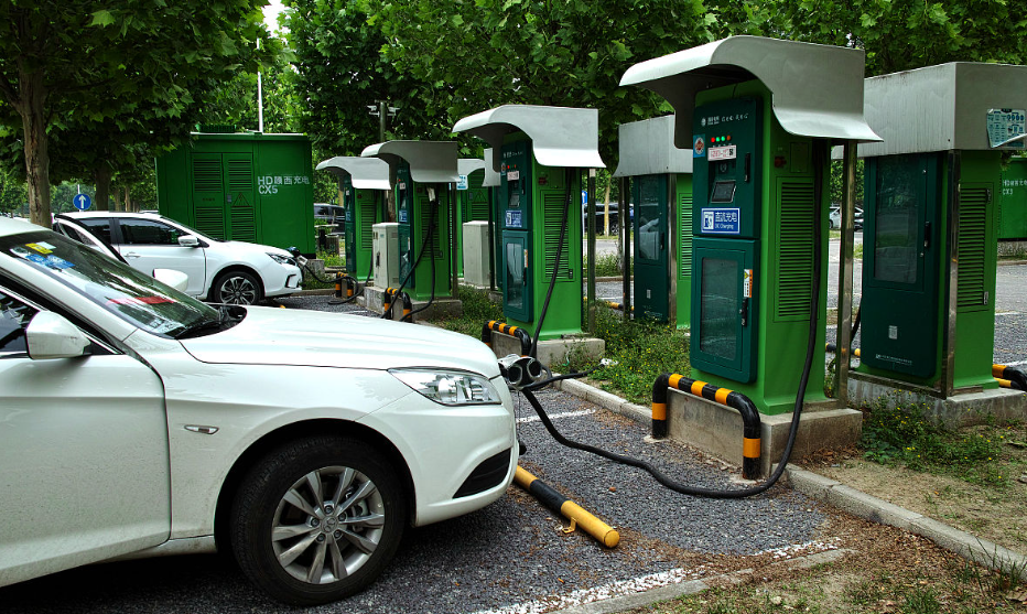
1. Motivation and Scope
I start from a practical observation: electric vehicle charging infrastructure is expanding rapidly, while photovoltaic generation is becoming one of the most accessible forms of distributed clean energy. In many buildings, campuses, and commercial sites, photovoltaic arrays are installed on roofs or canopies, and electric vehicle charging stations are installed in parking areas. In a conventional design, the photovoltaic array feeds a boost converter, then an inverter, then a transformer, then the alternating-current grid. The electric vehicle charging station may then receive alternating current from the grid, rectify it to direct current, and convert it again to the voltage required by the vehicle battery. Storage is often connected through yet another bidirectional alternating-current to direct-current converter. This arrangement is reliable and standardized, but it repeats voltage and current conversion stages. Each stage has conduction losses, switching losses, magnetic losses, and standby losses. The repeated conversion is particularly undesirable when the source, the storage medium, and the load are all direct current.
I therefore treat the electric vehicle charging station not as an alternating-current load that must be supplied from the grid in the usual way, but as a direct-current load that can be supplied from a direct-current bus. I also treat the battery storage system as a direct-current buffer that can exchange energy with the same bus. The photovoltaic array becomes the primary direct-current source. The grid remains available as a backup and as a sink for surplus energy, but it is no longer the mandatory intermediary for every kilowatt-hour delivered to an electric vehicle. This is the essential design choice that I evaluate. The approach is relevant to smart buildings, green campuses, commercial parking facilities, and any site where photovoltaic generation and electric vehicle charging coincide in time and space.
I use the term electric vehicle charging throughout this analysis because the charging load is the central end-use that justifies the architecture. The electric vehicle charging load is not constant. It depends on vehicle arrival times, state of charge, battery temperature, charger rating, user behavior, and tariff structure. This variability is precisely why storage and local photovoltaic generation can work well together. A direct-current bus allows the photovoltaic array, the battery, and the electric vehicle charging dispenser to exchange power with fewer conversions and with faster control response. I quantify the resulting savings and explain the conditions under which the architecture is most attractive.
2. Photovoltaic Source Model
I model the photovoltaic source by using the standard photoelectric equivalent circuit. The photovoltaic cell is represented by a current source in parallel with a diode and a shunt resistance, with a series resistance representing contact and material losses. The ideal current relation is:
$$I = I_L – I_D$$
The diode current follows an exponential relationship, so the ideal cell current can be written as:
$$I = I_L – I_0\left[\exp\left(\frac{qU}{nkT}\right)-1\right]$$
In a real photovoltaic cell, the series resistance and shunt resistance must be included. I use the following practical form:
$$I = I_L – I_0\left[\exp\left(\frac{q(U+IR_s)}{nkT}\right)-1\right]-\frac{U+IR_s}{R_{sh}}$$
Here, I is the terminal current, U is the terminal voltage, IL is the photogenerated current, I0 is the reverse saturation current, q is the elementary charge, n is the ideality factor, k is the Boltzmann constant, T is the cell temperature, Rs is the series resistance, and Rsh is the shunt resistance. The output power is:
$$P = UI$$
For maximum power point tracking, I use the condition that the derivative of power with respect to voltage is zero:
$$\frac{\partial P}{\partial U}=0$$
I use this model because it explains why the photovoltaic output voltage varies with irradiance and temperature, and why a direct-current bus needs a controlled interface. The photovoltaic array does not behave as an ideal fixed-voltage source. Its maximum power point moves. Therefore, a boost converter with maximum power point tracking is needed between the photovoltaic array and the direct-current bus. This converter is not an unnecessary conversion stage; it is the interface that allows the photovoltaic source to operate near its maximum power point while the bus voltage is regulated. The key design question is not whether to use a converter at the photovoltaic interface, but whether to avoid the additional inverter, transformer, rectifier, and charger rectifier stages that a conventional alternating-current architecture requires.
| Symbol | Meaning | Role in My Model |
|---|---|---|
| IL | Photogenerated current | Primary source term proportional to irradiance |
| I0 | Reverse saturation current | Determines diode behavior and temperature sensitivity |
| Rs | Series resistance | Represents contact and material losses |
| Rsh | Shunt resistance | Represents leakage and edge defects |
| U, I | Terminal voltage and current | Define operating point and power |
| P | Output power | Objective for maximum power point tracking |
3. Power-Electronic Interfaces
I model the photovoltaic boost converter as a continuous-conduction boost stage. The boost converter raises the photovoltaic voltage to the direct-current bus voltage and provides a controlled input current for maximum power point tracking. The ideal voltage relationship is:
$$\frac{V_o}{V_i}=\frac{1}{1-D}$$
where Vi is the input voltage, Vo is the output voltage, and D is the duty ratio. The inductor volt-second balance during one switching period gives:
$$V_i D T_s = (V_o – V_i)(1-D)T_s$$
This equation leads directly to the boost ratio. In practice, I include inductor resistance, switching losses, diode forward voltage, and capacitor equivalent series resistance. The maximum power point tracking controller adjusts D so that the photovoltaic operating point moves toward the maximum power point as irradiance and temperature change. The boost converter is therefore a controlled direct-current transformer rather than a simple voltage regulator. When the photovoltaic array is supplying an electric vehicle charging load through a direct-current bus, the boost converter output current is shared among the battery, the electric vehicle charging dispenser, and the grid interface. This shared direct-current bus is the core of the architecture.
For the alternating-current grid interface, I model a three-phase voltage-source inverter. When the three-phase voltages are balanced and the load is symmetrical, the neutral-point voltage can be expressed as:
$$V_{NN’}=\frac{1}{3}\left(V_{UN’}+V_{VN’}+V_{WN’}\right)$$
The inverter uses pulse-width modulation and current control to regulate active and reactive power. In a conventional architecture, this inverter is the mandatory gateway between the photovoltaic source and the alternating-current grid. In the direct-coupled architecture, I keep the inverter only for grid export, grid import, and grid support. It is not in the primary energy path from the photovoltaic array to the electric vehicle charging dispenser. This distinction is important because the inverter still exists, but its energy throughput is reduced. When the photovoltaic array is charging an electric vehicle directly through the direct-current bus, the inverter is idle or operating at low power. The conversion losses associated with the inverter are therefore avoided for the locally consumed energy.
For the electric vehicle charging dispenser, I model a two-stage conventional structure as a reference. The first stage is an active front-end rectifier that converts alternating current to direct current and performs power-factor correction. The second stage is an isolated direct-current to direct-current converter, often a full-bridge LLC resonant converter, that provides galvanic isolation and a wide output voltage range. In the conventional case, the electric vehicle charging station receives alternating current and performs these conversions. In the direct-coupled case, the first stage is eliminated for local photovoltaic and storage energy, and the charging dispenser receives direct current from the common bus. The charging dispenser still needs a direct-current to direct-current stage to match the vehicle battery voltage, but it does not need a rectifier for the locally supplied energy.
I model the LLC resonant stage by using its resonant frequency and its magnetizing-inductance-limited frequency. The series resonant frequency is:
$$f_r=\frac{1}{2\pi\sqrt{L_r C_r}}$$
The lower resonant frequency that includes the magnetizing inductance is:
$$f_m=\frac{1}{2\pi\sqrt{(L_m+L_r)C_r}}$$
These frequencies determine the gain range and soft-switching behavior. In my direct-current architecture, the LLC stage remains in the electric vehicle charging dispenser because the vehicle battery voltage varies widely. However, the input to this stage is the direct-current bus rather than a rectified grid voltage. The charger therefore becomes a direct-current to direct-current converter with a narrow input voltage range and a controlled output voltage range. This can improve efficiency because the converter does not have to compensate for grid voltage variation and rectifier ripple.
| Conversion Stage | Conventional Alternating-Current Coupling | Direct-Current Coupling | Effect on Electric Vehicle Charging |
|---|---|---|---|
| Photovoltaic boost | Required | Required | Maintains maximum power point and bus voltage |
| Grid inverter | Required for all photovoltaic energy | Required only for export or import | Reduces conversion for local electric vehicle charging |
| Transformer | Required for grid interface | Grid-side only | Not in the local photovoltaic-to-vehicle path |
| Charger rectifier | Required | Eliminated for local direct-current supply | Removes a major loss stage in electric vehicle charging |
| Charger direct-current converter | Required | Required | Matches vehicle battery voltage |
| Storage converter | Bidirectional alternating-current to direct-current | Bidirectional direct-current to direct-current | Simplifies storage exchange and improves response |
4. Energy Storage and Electric Vehicle Charging Load
I model the battery storage system as a direct-current energy buffer. The required capacity depends on the load power, the backup duration, the battery efficiency, and the allowable depth of discharge. I use the following sizing relation:
$$C_b=\frac{P_o t_b}{\eta_b D_{soc}}$$
where Cb is the required battery capacity, Po is the load power, tb is the discharge duration, ηb is the battery conversion efficiency, and Dsoc is the usable depth of discharge. For an electric vehicle charging site, the load power is not simply the sum of charger nameplate ratings. I use a diversified load profile because electric vehicle charging events are stochastic. The storage system can absorb photovoltaic surplus, reduce peak grid demand, and provide a buffer when a high-power electric vehicle charging session begins.
The battery state of charge is updated by:
$$SOC_{t+1}=SOC_t+\frac{\eta_{ch}P_{ch,t}\Delta t}{C_b}-\frac{P_{dis,t}\Delta t}{\eta_{dis}C_b}$$
where Pch,t is the charging power, Pdis,t is the discharging power, ηch is the charging efficiency, and ηdis is the discharging efficiency. I enforce upper and lower state-of-charge limits:
$$SOC_{min}\le SOC_t\le SOC_{max}$$
I also enforce power limits:
$$0\le P_{ch,t}\le P_{ch,max}$$
$$0\le P_{dis,t}\le P_{dis,max}$$
The electric vehicle charging load is modeled as a set of charging sessions. Each session has an arrival time, a departure time, an energy demand, and a maximum charging power. For a session j, the energy delivered is:
$$E_j=\int_{t_{a,j}}^{t_{d,j}} P_j(t)dt$$
where ta,j is the arrival time and td,j is the departure time. The charging power is constrained by the vehicle and charger limits:
$$0\le P_j(t)\le \min(P_{veh,j},P_{charger,j})$$
In my direct-coupled architecture, the electric vehicle charging dispenser can draw power simultaneously from the photovoltaic array, the battery, and the grid. The control system decides the split according to photovoltaic availability, state of charge, tariff, and user demand. The goal is to maximize local photovoltaic consumption while maintaining reliable electric vehicle charging. This is a multi-objective problem. I prioritize driver satisfaction and battery safety first, then minimize cost and losses, and then minimize grid impact. The direct-current bus makes the power split fast and smooth because all sources and loads share the same direct-current voltage reference.
| Load or Storage Parameter | Role in Electric Vehicle Charging Operation | Control Implication |
|---|---|---|
| Arrival time | Determines when charging demand appears | Used for forecast and scheduling |
| Departure time | Defines flexibility window | Allows delayed charging when photovoltaic is low |
| Energy demand | Sets total energy per session | Used for energy allocation and storage reservation |
| Maximum power | Limits instantaneous charger output | Prevents transformer overload |
| State of charge | Defines battery storage availability | Protects battery and reserves capacity |
| Depth of discharge | Sets usable storage energy | Balances cycling cost and backup capability |
5. Direct-Coupled Architecture
I design the direct-coupled architecture around a common direct-current bus. The photovoltaic array feeds a boost converter, which regulates the bus voltage and performs maximum power point tracking. The battery storage system connects to the bus through a bidirectional direct-current to direct-current converter. The electric vehicle charging dispenser connects to the bus through an isolated direct-current to direct-current converter. The grid connects through a bidirectional alternating-current to direct-current converter and a transformer. The energy management system coordinates all converters and schedules electric vehicle charging sessions.
The primary energy path for local photovoltaic energy is:
$$PV \rightarrow DC/DC\ boost \rightarrow DC\ bus \rightarrow DC/DC\ charger \rightarrow EV\ battery$$
When storage is involved, the path becomes:
$$PV \rightarrow DC/DC\ boost \rightarrow DC\ bus \rightarrow bidirectional\ DC/DC \rightarrow battery \rightarrow bidirectional\ DC/DC \rightarrow DC\ bus \rightarrow DC/DC\ charger \rightarrow EV\ battery$$
When the battery is discharging to support electric vehicle charging, the path is:
$$battery \rightarrow bidirectional\ DC/DC \rightarrow DC\ bus \rightarrow DC/DC\ charger \rightarrow EV\ battery$$
These paths contain fewer alternating-current conversion stages than the conventional path:
$$PV \rightarrow DC/DC\ boost \rightarrow DC/AC\ inverter \rightarrow transformer \rightarrow AC\ grid \rightarrow AC/DC\ rectifier \rightarrow DC/DC\ charger \rightarrow EV\ battery$$
In the conventional case, the electric vehicle charging station must rectify grid alternating current even when the photovoltaic array is producing power at the same site. In the direct-coupled case, the electric vehicle charging station receives direct current from the bus. The rectifier is bypassed for local energy. The grid remains available for backup and for exporting surplus photovoltaic energy. This is the main source of savings.
| Design Aspect | Conventional Alternating-Current Coupling | My Direct-Current Coupling |
|---|---|---|
| Primary bus | Alternating-current grid | Common direct-current bus |
| Photovoltaic interface | Boost and inverter | Boost only for local use |
| Storage interface | Bidirectional alternating-current to direct-current converter | Bidirectional direct-current to direct-current converter |
| Electric vehicle charging interface | Rectifier and direct-current converter | Direct-current converter for local supply |
| Local photovoltaic consumption | Limited by alternating-current coordination | Enhanced by direct-current power sharing |
| Grid interaction | All energy passes through grid | Grid is backup, export, and import path |
| Conversion stages for local charging | High | Low |
6. Power Balance and Optimization Model
I use a power-balance model to represent the direct-current bus. The grid input power, photovoltaic input power, electric vehicle charging power, and storage output power are related by:
$$P_1=P_3-P_2-P_4$$
where P1 is the grid input power, P2 is the photovoltaic input power, P3 is the electric vehicle charging input power, and P4 is the storage output power. Positive storage output means discharge. The equation is a sign convention. If photovoltaic and storage together exceed the electric vehicle charging demand, the surplus is exported to the grid. If they are insufficient, the grid supplies the difference.
I define three operating regions. In the first region, the photovoltaic and storage system cannot meet the electric vehicle charging load:
$$P_2+P_4 \lt 0$$
In the second region, the photovoltaic and storage system partially supplies the electric vehicle charging load:
$$0\le P_2+P_4\le P_3$$
In the third region, the photovoltaic and storage system exceeds the electric vehicle charging load and exports energy:
$$P_3\lt P_2+P_4$$
I optimize the system over a daily horizon. The objective is to maximize economic benefit while respecting technical constraints. A simplified objective is:
$$\max \sum_t \left(P_{2,t}p_{ct}-P_{1,t}p_{at}\right)\Delta t$$
where pct is the electric vehicle charging price, pat is the grid tariff at time t, and Δt is the time step. The first term represents revenue from electric vehicle charging, and the second term represents the cost of grid import. I also include a penalty for unmet electric vehicle charging demand and a penalty for violating battery limits. The optimization is subject to the power-balance equation, state-of-charge dynamics, converter limits, and charging-session constraints.
In practice, I use a model predictive control layer. At each time step, the controller forecasts photovoltaic generation and electric vehicle charging demand for the next horizon. It solves a rolling optimization problem and applies the first control action. This approach handles forecast errors and unexpected electric vehicle arrivals. The direct-current bus makes the control action fast because the converters can adjust power without changing the alternating-current grid interface. The energy management system coordinates the photovoltaic boost converter, the battery converter, the charger converter, and the grid converter. The control hierarchy is:
| Control Layer | Time Scale | Main Function | Electric Vehicle Charging Relevance |
|---|---|---|---|
| Converter control | Microseconds to milliseconds | Regulate voltage, current, and power | Maintains stable charging power |
| Session control | Seconds to minutes | Allocate power among chargers | Respects vehicle limits and user needs |
| Energy management | Minutes to hours | Schedule storage and grid exchange | Maximizes local photovoltaic use |
| Economic dispatch | Hours to day | Optimize tariffs and peak demand | Reduces electric vehicle charging cost |
7. Route Efficiency and Loss Analysis
I define the route efficiency as the product of the efficiencies of all conversion stages in the energy path:
$$\eta_{route}=\prod_{k=1}^{m}\eta_k$$
The route loss rate is:
$$L_{route}=1-\eta_{route}$$
This formula shows why the number and quality of conversion stages matter. If a route contains more stages, the product becomes smaller and the loss becomes larger. The direct-coupled architecture reduces the number of stages in the local photovoltaic-to-electric-vehicle path. I evaluate four representative routes:
| Route | Energy Path Description | Modeled Loss Rate | Implication for Electric Vehicle Charging |
|---|---|---|---|
| Conventional with storage | Photovoltaic to grid, grid to storage, storage to grid, grid to charger | 26.7% | Highest conversion burden |
| Conventional without storage | Photovoltaic to grid, grid to charger | 17.2% | Still includes inverter and rectifier |
| Direct with storage | Photovoltaic to direct-current bus, battery, bus, charger | 13.5% | Fewer alternating-current stages |
| Direct without storage | Photovoltaic to direct-current bus, charger | 8.9% | Lowest loss for local electric vehicle charging |
I use these loss rates to compare the architectures. The difference between the conventional with-storage route and the direct with-storage route is about 13.2 percentage points. The difference between the conventional without-storage route and the direct without-storage route is about 8.3 percentage points. When I combine the two operating modes according to a mixed daily profile, the aggregate reduction is about 9.7 percentage points. These values are not universal constants; they depend on converter efficiencies, cable lengths, transformer losses, and operating points. However, the direction of the result is robust: direct coupling reduces conversion losses for local electric vehicle charging.
The efficiency improvement has two effects. First, more photovoltaic energy reaches the electric vehicle battery for the same generation. Second, less grid energy is needed when photovoltaic and storage are insufficient. The first effect increases renewable utilization. The second effect reduces operating cost and indirect emissions. For a site with high electric vehicle charging demand during photovoltaic production hours, the benefit is especially large. For a site with mostly nighttime electric vehicle charging, storage becomes more important, and the direct-current bus still helps because the battery can charge from photovoltaic during the day and discharge at night with fewer conversions.
8. Case-Based Calculation
I apply the model to a representative building-scale system. The photovoltaic array has a rated capacity of 210 kWp and uses 420 modules rated at 500 Wp each. The array output is about 200 V direct current and is boosted to an 800 V direct-current bus. The battery storage system has a capacity of 150 kWh and operates between 10% and 90% state of charge. I assume two charge-discharge cycles per day for peak-valley adjustment, with a discharge rate of 0.8 C and a one-hour discharge period per cycle. The electric vehicle charging dispenser is rated at 120 kW with two guns and provides an output voltage range of 200 V to 1000 V. The annual photovoltaic utilization time is 1450 hours, so the annual generation is:
$$E_{PV}=210\ \mathrm{kWp}\times 1450\ \mathrm{h}=304500\ \mathrm{kWh}$$
The modeled annual conversion and transmission loss is 29,578 kWh. This corresponds to a loss rate of:
$$L_{annual}=\frac{29578}{304500}\approx 9.71\%$$
This value is consistent with the aggregate loss reduction estimate of about 9.7% in my route comparison. The annual carbon emission reduction from avoided conversion and transmission loss is about 25.2 t. The total annual carbon emission reduction from the photovoltaic generation is about 258.8 t. These results are site-specific, but they show the order of magnitude. The direct-coupled architecture does not eliminate all losses. It reduces the losses that are created by unnecessary alternating-current conversion in the electric vehicle charging path.
| Parameter | Value | Unit | Role in Electric Vehicle Charging Case |
|---|---|---|---|
| Photovoltaic rated capacity | 210 | kWp | Primary local clean energy source |
| Module count and rating | 420 × 500 | Wp | Defines array configuration |
| Photovoltaic direct-current voltage | 200 | V | Input to boost converter |
| Direct-current bus voltage | 800 | V | Common coupling voltage |
| Battery capacity | 150 | kWh | Buffers photovoltaic and electric vehicle charging |
| State-of-charge window | 10 to 90 | % | Protects battery and provides usable energy |
| Discharge rate | 0.8 | C | Supports peak electric vehicle charging |
| Charger rating | 120 | kW | Two-gun fast electric vehicle charging |
| Charger output voltage | 200 to 1000 | V | Matches multiple vehicle battery classes |
| Annual photovoltaic utilization | 1450 | h | Determines annual generation |
| Annual generation | 304500 | kWh | Clean energy available for electric vehicle charging |
| Annual conversion and transmission loss | 29578 | kWh | Loss in the modeled direct-current case |
| Annual loss rate | 9.71 | % | Matches the aggregate route estimate |
| Annual emission reduction from loss avoidance | 25.2 | t | Benefit of reduced conversion |
| Annual emission reduction from photovoltaic generation | 258.8 | t | Total clean energy benefit |
I also compare the annual operating behavior under three control strategies. In the first strategy, the system prioritizes electric vehicle charging with photovoltaic energy and uses the battery only when photovoltaic is insufficient. In the second strategy, the system prioritizes battery charging during low tariffs and discharges during high tariffs, while electric vehicle charging uses the grid as needed. In the third strategy, the system co-optimizes photovoltaic self-consumption, battery cycling, and electric vehicle charging. The third strategy gives the best economic result because it uses the direct-current bus to shift energy in time and reduce peak demand.
| Operating Strategy | Photovoltaic Self-Consumption | Battery Cycling | Electric Vehicle Charging Cost | Overall Effect |
|---|---|---|---|---|
| Photovoltaic-first | High during daytime | Low to moderate | Low during photovoltaic hours | Good renewable use, weaker tariff arbitrage |
| Tariff-first | Moderate | High | Lower at peak hours | Good cost saving, possible photovoltaic curtailment |
| Co-optimized | High | Moderate and controlled | Lowest overall | Best balance of cost, emissions, and battery life |
9. Control and Operational Strategy for Electric Vehicle Charging
I design the control strategy around the needs of electric vehicle charging. The first priority is safety. The charger must respect the vehicle battery voltage and current limits. The second priority is user satisfaction. The charger should deliver the requested energy before departure whenever possible. The third priority is economic and environmental performance. The controller should use photovoltaic energy first, then battery energy within its state-of-charge limits, and then grid energy. The fourth priority is grid support. The controller should avoid unnecessary peak demand and should export surplus photovoltaic energy only when it is economically or technically beneficial.
I implement this hierarchy with a rule-based layer and an optimization layer. The rule-based layer handles immediate constraints. For example, if a vehicle requests 120 kW and the photovoltaic array produces 80 kW, the battery can supply 40 kW if its state of charge is above the reserve threshold. If the battery is below the threshold, the grid supplies the difference. The optimization layer plans battery charging and discharging over the day. It considers photovoltaic forecast, electric vehicle charging forecast, tariff, and battery degradation. The two layers interact through power setpoints. This structure is practical because it separates fast protection from slow economic scheduling.
The direct-current bus also enables a useful feature for electric vehicle charging: dynamic power sharing. When two vehicles are charging at the same dispenser, the controller can allocate power according to user priority, state of charge, and departure time. If one vehicle has a high state of charge and a long dwell time, it can receive less power while the other vehicle receives more. This flexibility reduces peak demand and improves photovoltaic self-consumption. In an alternating-current-coupled system, power sharing is also possible, but the charger still processes the energy through its rectifier. In the direct-coupled system, the power sharing happens on the direct-current bus, and the charger only performs the final voltage conversion.
| Control Mode | Trigger Condition | Action | Benefit for Electric Vehicle Charging |
|---|---|---|---|
| Photovoltaic surplus mode | Photovoltaic output exceeds load and storage demand | Charge battery, then export surplus | Maximizes local renewable use |
| Photovoltaic support mode | Photovoltaic output is high and electric vehicle demand is high | Supply charger from bus and limit grid import | Reduces electric vehicle charging cost |
| Storage discharge mode | High tariff or peak load | Discharge battery to bus | Shaves peak electric vehicle charging demand |
| Grid backup mode | Photovoltaic and storage are insufficient | Import grid power within limits | Maintains charging reliability |
| Protection mode | Voltage or current exceeds limits | Reduce or stop charging power | Protects vehicles, chargers, and storage |
10. Discussion
I find that the direct-coupled architecture is most valuable when three conditions hold. First, photovoltaic generation and electric vehicle charging overlap in time. Second, the site has a high electric vehicle charging demand that would otherwise require a large grid connection or a large rectifier capacity. Third, the storage system is sized to absorb photovoltaic surplus and to support peak charging. When these conditions are met, the direct-current bus reduces conversion losses and improves local energy use. When they are not met, the benefit is smaller. For example, a site with only nighttime electric vehicle charging and no storage cannot use daytime photovoltaic energy directly. The storage system becomes the critical link, and the direct-current bus still helps by reducing storage interface losses, but the overall benefit depends on the battery capacity and cycling cost.
I also note that direct coupling introduces new design requirements. The direct-current bus must have coordinated protection. The converters must be compatible with the bus voltage range. The electric vehicle charging dispenser must accept a direct-current input. The energy management system must handle multiple converters and multiple charging sessions. These requirements are manageable, but they must be addressed in the design stage. The architecture is not a simple replacement of one converter. It is a system-level redesign that changes the energy flow, the control hierarchy, and the protection strategy.
| Aspect | Benefit of Direct Coupling | Design Consideration |
|---|---|---|
| Conversion loss | Fewer alternating-current stages | Converter efficiency and bus voltage regulation |
| Local photovoltaic use | Higher self-consumption for electric vehicle charging | Forecasting and session scheduling |
| Grid impact | Lower peak demand and smoother import | Grid interface control and protection |
| Storage integration | Simpler direct-current coupling | State-of-charge management and battery degradation |
| Electric vehicle charging reliability | Multiple sources share the bus | Fault isolation and charger compatibility |
| Cost | Reduced conversion equipment for local energy | Initial design and standardization effort |
From an economic perspective, I expect the largest savings in sites with high electric vehicle charging throughput and high photovoltaic penetration. The savings come from three sources: reduced energy losses, reduced peak demand charges, and increased photovoltaic self-consumption. The first source is directly proportional to the energy routed through the direct-current bus. The second source depends on the tariff structure and the site load profile. The third source depends on the match between photovoltaic generation and electric vehicle charging demand. I use the route-efficiency model to estimate the first source and the optimization model to estimate the second and third sources. The case calculation shows that the annual loss avoidance can be several tens of megawatt-hours for a modest 210 kWp photovoltaic array. For larger sites, the absolute savings scale with energy throughput.
I also consider the role of the electric vehicle charging load in building energy management. In a smart building, electric vehicle charging can be a flexible load. The building can shift charging to periods of high photovoltaic generation or low grid prices. The direct-current bus makes this flexibility more effective because the charging dispenser can follow the bus power setpoint quickly. The building energy management system can coordinate heating, ventilation, air conditioning, lighting, and electric vehicle charging. The direct-current bus provides a common electrical backbone for photovoltaic, storage, and electric vehicle charging. This is a practical step toward a low-carbon building with high renewable self-consumption.
11. Limitations and Future Work
I acknowledge several limitations in my analysis. The route-efficiency values are based on representative converter efficiencies and a specific operating profile. In a real project, the efficiencies vary with load, temperature, and manufacturer. The battery degradation model is simplified. The electric vehicle charging demand is stochastic, and the forecast error affects the optimization result. The economic analysis depends on tariff structure, capital cost, and incentive policy. These limitations do not invalidate the main conclusion, but they define the boundaries of the result. A detailed engineering design should use measured efficiency curves and site-specific load data.
Future work should focus on three areas. First, I recommend using wide-bandgap semiconductor devices in the photovoltaic boost converter, the battery converter, and the electric vehicle charging converter. Silicon carbide and gallium nitride devices can reduce switching losses and increase power density. Second, I recommend improving the coordination between the direct-current bus and the building energy management system. The controller should use machine learning to forecast electric vehicle charging demand and photovoltaic generation. Third, I recommend developing standardized direct-current interfaces for electric vehicle charging and storage. Standardization will reduce engineering cost and improve interoperability. These improvements can further reduce losses and increase the value of direct-coupled photovoltaic green power for electric vehicle charging.
12. Conclusion
I have presented a direct-coupled photovoltaic, storage, and electric vehicle charging architecture and compared it with a conventional alternating-current-coupled design. The direct-coupled architecture uses a common direct-current bus to connect the photovoltaic array, the battery storage system, and the electric vehicle charging dispenser. It removes unnecessary alternating-current conversion stages from the local energy path. The equivalent-circuit model explains the photovoltaic source behavior. The boost, inverter, rectifier, and LLC models explain the conversion stages. The power-balance and route-efficiency equations explain the energy flow and loss. The case calculation shows that the direct-coupled architecture can reduce annual conversion and transmission losses, increase local photovoltaic consumption, and reduce carbon emissions. The key insight is simple: when the source, the storage, and the electric vehicle charging load are all direct current, direct coupling is the natural choice. I conclude that direct-coupled photovoltaic green power is a practical and effective way to support electric vehicle charging in low-carbon buildings and campuses.