
1. Introduction
The rapid proliferation of electric vehicles (EVs) necessitates advanced educational tools to bridge industry-academia gaps. This article details my design of a CAN bus-controlled electric vehicle charging system teaching platform, addressing offline performance testing challenges in EV courses. The platform integrates hardware, software, and pedagogical frameworks to simulate real-world charging scenarios, enabling students to master CAN communication protocols, fault diagnosis, and system optimization.
2. Electric Vehicle Charging System Fundamentals
2.1 System Architecture
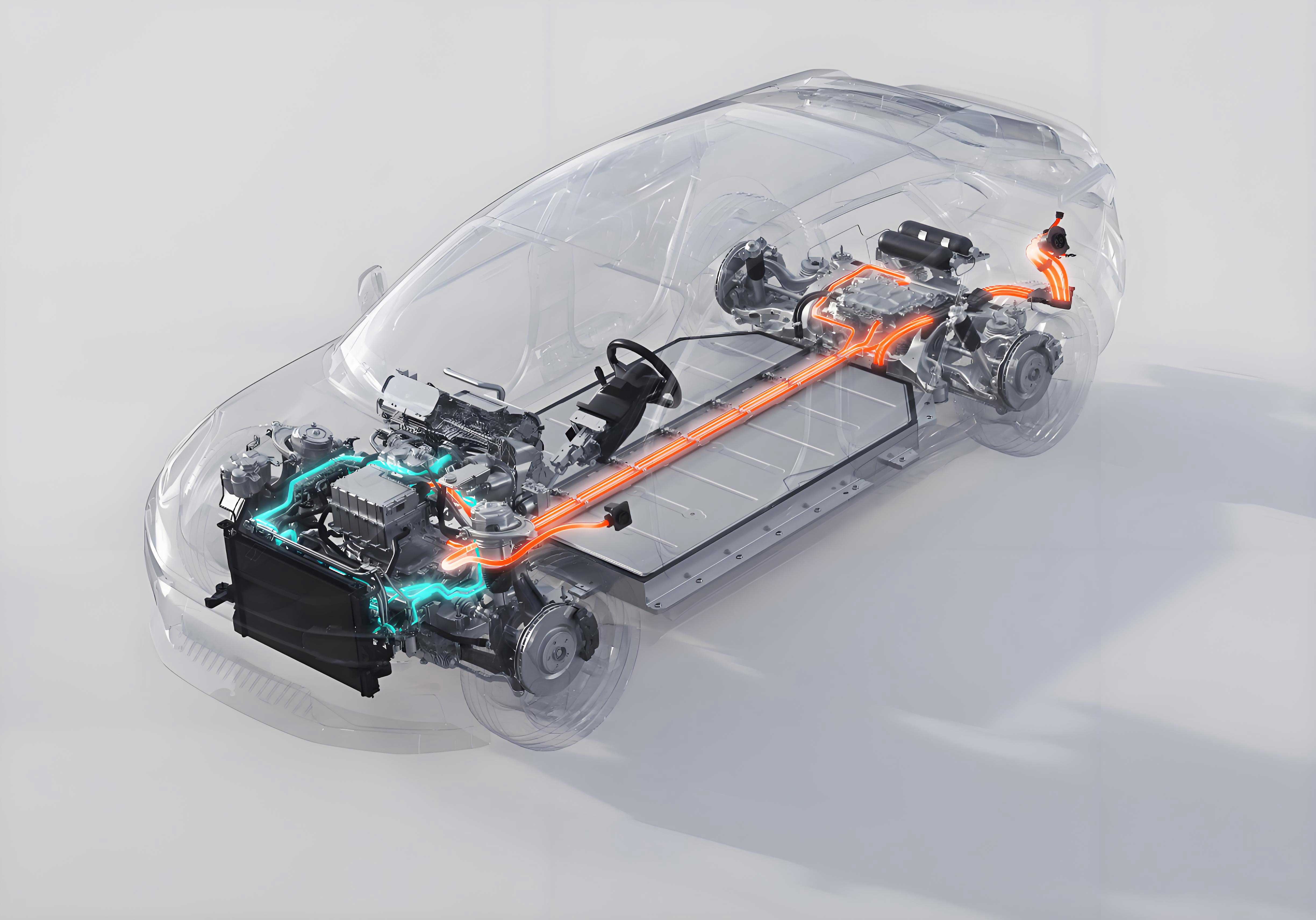
The electric vehicle charging system comprises:
- AC/DC Charging Sockets: Interface for power delivery.
- Battery Management System (BMS): Monitors cell voltage, temperature, and State of Charge (SOC).
- High-Voltage Control Unit: Integrates OBC (On-Board Charger), DC-DC converter, and VTOG (Vehicle-to-Grid module).
2.2 CAN Bus Communication Protocol
CAN 2.0B (ISO 11898) enables real-time data exchange between subsystems. Critical parameters include:
- Identifier (ID): 11/29-bit message priority tag.
- Data Frame: 0–8 bytes payload.
- Bit Rate: Configurable from 5 kbit/s to 1 Mbit/s.
The CAN signal voltage differential is:Vdiff=VVdiff=V
3. Platform Hardware Design
3.1 Component Selection
Table 1: Core Hardware Specifications
| Component | Specifications | Function |
|---|---|---|
| USB-CAN Interface Card | 2 channels, 5 kbit/s–1 Mbit/s, ISO 11898 | PC-to-CAN bus gateway |
| AC Power Supply | 220V ±5%, 50 Hz, 7 kW | Simulates grid input |
| DC Power Supply | 0–15V, 0–20A adjustable | Low-voltage system emulation |
| Ripple Load Resistor | RXG20, 1500W ×5 (series) | Dissipates OBC output power |
| Custom Harnesses | High-voltage connectors, CC/CP signal lines | Replicates EV-specific interfaces |
3.2 Circuit Topology
- OBC Control Path:PC→USBUSB-CANPCUSBUSB-CAN
- Load Circuit:OBC Output→Rload=∑i=15ROBC Output→Rload=i=1∑5R
4. Software Architecture
4.1 CANTest Software Workflow
- Initialize USB-CAN interface (500 kbit/s baud rate).
- Configure message ID filters.
- Transmit/receive CAN frames via GUI.
- Log voltage (VoutVout), current (IoutIout), SOC in real-time.
Table 2: Critical CAN Message IDs
| Subsystem | ID (Hex) | Data Fields |
|---|---|---|
| BMS | 0x18FF50E5 | SOC, Voltage, Temperature, Faults |
| OBC | 0x1806E5F4 | VoutVout, IoutIout, PWM Status |
| Charger | 0x101 | Start/Stop Command, Max Current |
4.2 PWM Signal Control
For AC slow charging, CP signal modulation:Duty Cycle=TONTTotal×100%Duty Cycle=TTotalTON×100%
where:
- TONTON: High-state duration,
- TTotalTTotal: Period (1 kHz default).
5. Platform Testing & Validation
5.1 Performance Metrics
Table 3: 60-Second Load Test Results
| Parameter | Value | Acceptance Criteria | Status |
|---|---|---|---|
| Output Voltage (VoutVout) | 442 V | 400–450 V | Pass |
| Output Current (IoutIout) | 3.92 A | 3.8–4.2 A | Pass |
| Low-Voltage Supply | 12.3 V | 12.0–12.6 V | Pass |
| Ripple Current | < 0.5 A | ≤ 1 A | Pass |
5.2 Fault Simulation Logic
- BMS Fault Injection:
Send CAN frame0x18FF50E5withSOC = 0xFF(invalid). - OBC Overcurrent Test:Ilimit=Irated×1.2(Trip threshold)Ilimit=Irated×1.2(Trip threshold)
6. Educational Framework
6.1 Learning Modules
- CAN Protocol Decoding:
- Parse ID, DLC, and data fields from captured frames.
- Charging Workflow Emulation:
- AC slow charge: Simulate CP/CC handshake via PWM.
- DC fast charge: Validate insulation tests (ISO 6469).
- Fault Diagnosis:
- Use CAN logs to identify BMS/OBC mismatches.
6.2 Skill Outcomes
- Mastery of SAE J1772/IEC 61851 charging standards.
- Competence in CANalyzer/CANoe-based diagnostics.
- Ability to validate electric vehicle charging post-repair.
7. Conclusion
This platform revolutionizes electric vehicle charging system education by:
- Enabling Offline Testing: Replace in-vehicle validation with lab-safe procedures.
- Standardizing CAN Workflows: Teach industry-relevant communication protocols.
- Scaling for Multi-Vehicle Support: Adapt via customizable CAN databases.
Future enhancements will integrate wireless charging (Qi/PMA standards) and bidirectional V2G emulation, further aligning with evolving electric vehicle technologies.