
In the context of global carbon neutrality goals, the development of new energy vehicles, particularly electric vehicles (EVs), has become a strategic priority worldwide. As a key component, the power battery system directly impacts the safety, performance, and energy efficiency of EVs. The battery box, which houses the power batteries, must meet stringent requirements for mechanical strength, vibration resistance, and lightweight design. In China, the rapid expansion of the EV market has driven intensive research into optimizing China EV battery systems to enhance their structural integrity and reduce weight. This study focuses on the finite element analysis (FEA) and structural optimization of an EV power battery box, utilizing advanced simulation techniques to predict its static and dynamic behaviors under typical operating conditions. By employing methods such as static strength analysis and modal analysis, I aim to reduce the weight of the battery box while improving its low-order modal frequencies, thereby minimizing the risk of resonance and enhancing overall safety. The optimization process involves partitioning the battery box into five key regions and adjusting wall thicknesses using response surface methodology, resulting in a significant weight reduction and improved dynamic performance. Throughout this article, I will emphasize the importance of China EV battery innovations and EV power battery advancements, supported by tables and mathematical formulations to summarize key findings. The integration of these approaches not only aligns with China’s industrial policies but also contributes to the global effort toward sustainable transportation solutions.
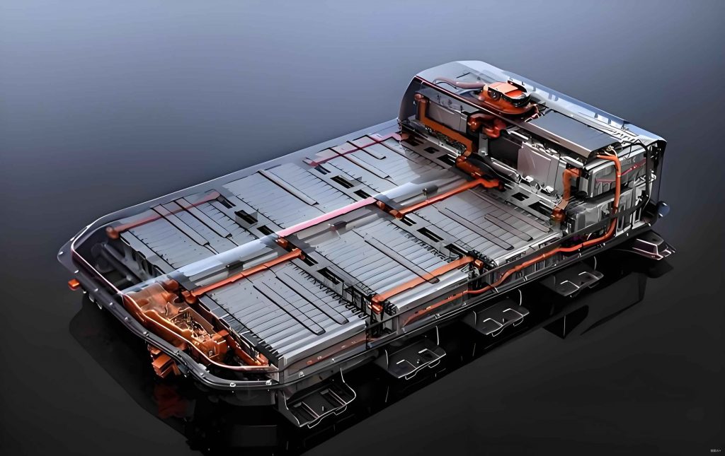
The initial design of the EV power battery box was based on the Cell-to-Pack (CTP) methodology, which allows for larger battery modules and better space utilization. The battery box envelope dimensions were set at 1,454 mm in length, 720 mm in width, and 190 mm in height, accommodating four battery modules arranged in a flat configuration on the vehicle chassis. Each module consisted of 24 cells in series, with a total system capacity of 41.18 kWh. The material selected for the box was AL-6063-T6 aluminum alloy, known for its high strength-to-weight ratio, which is crucial for China EV battery applications. The box structure included internal crossbeams for support and fixation of the battery modules, welded using friction stir and MIG processes to ensure sealing reliability. The initial weight of the battery box was approximately 63 kg, which presented an opportunity for lightweight optimization. In this study, I employed finite element analysis to evaluate the structural performance under critical scenarios, such as collision extrusion and emergency braking, as per the GB/T 31467.3 safety standard. The primary goal was to reduce mass while maintaining or enhancing mechanical properties, a key aspect of EV power battery development in China.
To establish the finite element model, I imported the 3D geometry of the battery box into ANSYS software and performed geometric cleanup to simplify non-essential features like fillets and small holes, improving computational efficiency. The model was meshed using shell elements, with a combination of quadrilateral and triangular elements to capture complex regions such as吊耳 (lifting lugs) and corners. The mesh size was set to 5 mm globally, with refinements to 3 mm at critical areas, resulting in a model with 332,742 elements and 1,390,079 nodes. Connections, including welds and bolts, were simulated using ACM elements and rigid body elements, respectively, to accurately represent the structural integrity. For static analysis, I considered two典型工况 (typical working conditions): collision extrusion with a force of 100 kN applied in the X and Y directions, and emergency braking with an acceleration of 3g in the X-direction. The static strength was evaluated using the von Mises stress criterion, where the stress $\sigma$ is given by:
$$ \sigma = \sqrt{\frac{(\sigma_1 – \sigma_2)^2 + (\sigma_2 – \sigma_3)^2 + (\sigma_3 – \sigma_1)^2}{2}} $$
Here, $\sigma_1$, $\sigma_2$, and $\sigma_3$ are the principal stresses. The displacement and stress distributions were analyzed to ensure that the maximum values did not exceed the material’s yield strength of 280 MPa for AL-6063-T6. For dynamic analysis, I conducted constraint modal analysis by fixing the bolt holes on both sides and extracting the first three natural frequencies and mode shapes. The governing equation for modal analysis is:
$$ [K] \{\phi_i\} = \omega_i^2 [M] \{\phi_i\} $$
where $[K]$ is the stiffness matrix, $[M]$ is the mass matrix, $\omega_i$ is the angular frequency, and $\{\phi_i\}$ is the mode shape vector for the i-th mode. This approach helps in identifying resonance risks and guiding structural improvements for EV power battery systems.
The static analysis under collision extrusion in the X-direction revealed a maximum displacement of 12.46 mm and a stress of 323.52 MPa at the side wall corners, which exceeded the yield strength but was acceptable as a destructive scenario. Similarly, the Y-direction extrusion showed a displacement of 8.47 mm and a stress of 144.51 MPa, within safe limits. For emergency braking, the displacement was 1.12 mm, and the stress was 65.6 MPa, indicating no failure risk. The modal analysis results are summarized in Table 1, showing the first three natural frequencies and their corresponding mode shapes. The first-order frequency was 162.15 Hz, which is outside the common excitation range of 17–25 Hz for vehicles, but there was room for improvement to avoid potential resonance when accounting for additional mass from battery modules.
| Mode Order | Frequency (Hz) | Mode Shape Description |
|---|---|---|
| 1 | 162.15 | Bending mode of the box base |
| 2 | 201.49 | Torsional mode around Y-axis |
| 3 | 215.79 | Bending mode of the rear beam |
Based on the initial analysis, I proceeded with structural optimization to reduce weight and enhance low-order modal frequencies. The battery box was divided into five regions: X-direction side walls, Y-direction side walls, central base plate, side base plates, and module support beams. The wall thicknesses of these regions, denoted as $t_1$ to $t_5$, were treated as design variables with specified ranges, as shown in Table 2. I used the moving least squares method to fit response surfaces for the mass and frequency objectives, ensuring smooth and continuous approximations. Two optimization schemes were formulated: Scheme 1 aimed to minimize mass and maximize the first-order frequency while constraining emergency braking displacement to the original value, and Scheme 2 added a constraint on extrusion displacement to prevent intrusion into the battery modules. The mathematical formulation for Scheme 2 is:
$$ \text{minimize} \quad \{ M, -F \} $$
$$ \text{subject to} \quad D_1 \leq D_3, \quad D_2 \leq D_4 $$
$$ T = (t_1, t_2, t_3, t_4, t_5)^T $$
$$ 2.00 \leq t_1, t_5 \leq 8.00 $$
$$ 2.00 \leq t_2 \leq 7.50 $$
$$ 1.50 \leq t_3, t_4 \leq 7.00 $$
where $M$ is the mass, $F$ is the first-order frequency, $D_1$ and $D_2$ are the displacements under emergency braking and extrusion, respectively, and $D_3$ and $D_4$ are the allowable displacements. After iterative optimization, the optimal thickness values were rounded and validated through simulation. The comparison of initial and optimized thicknesses is presented in Table 2, and the performance metrics are summarized in Table 3. Scheme 2 was selected as the final design due to its better balance of weight reduction and safety margins.
| Design Variable | Initial Value (mm) | Optimized Value (mm) | Rounded Value (mm) |
|---|---|---|---|
| $t_1$ (X-side wall) | 6.0 | 5.12 | 5.1 |
| $t_2$ (Y-side wall) | 6.0 | 4.48 | 4.5 |
| $t_3$ (Central base) | 5.0 | 3.83 | 3.8 |
| $t_4$ (Side base) | 5.0 | 4.01 | 4.0 |
| $t_5$ (Support beam) | 5.0 | 5.89 | 5.9 |
| Parameter | Initial Design | Scheme 1 | Scheme 2 |
|---|---|---|---|
| Mass (kg) | 63 | 54 | 52 |
| X-extrusion Displacement (mm) | 12.46 | 14.86 | 13.24 |
| Y-extrusion Displacement (mm) | 8.47 | 9.79 | 9.07 |
| Emergency Braking Displacement (mm) | 1.12 | 1.05 | 0.93 |
| First-Order Frequency (Hz) | 162.15 | 172.50 | 180.79 |
The optimized design from Scheme 2 was subjected to further FEA validation to confirm its performance under critical conditions. For collision extrusion in the X-direction, the maximum displacement was 13.19 mm, which is within the 15 mm safety margin, and the stress was 275 MPa, below the yield strength. In the Y-direction, the displacement was 9.0 mm with a stress of 223.45 MPa, both satisfying the safety requirements. The modal analysis of the optimized box showed a first-order frequency of 185.61 Hz, a 14% increase from the initial design, and the mode shapes indicated reduced amplitudes, with the first-order bending mode amplitude decreasing by 34% to 8.57 mm. The second and third modes also showed improvements, with no torsional modes observed, highlighting the effectiveness of the optimization for EV power battery applications. The natural frequency $\omega_i$ can be related to the stiffness and mass through the formula:
$$ \omega_i = 2\pi f_i = \sqrt{\frac{k_i}{m_i}} $$
where $f_i$ is the frequency, $k_i$ is the effective stiffness, and $m_i$ is the effective mass for the i-th mode. This demonstrates how reducing mass while optimizing stiffness can enhance dynamic performance.
In conclusion, this study successfully demonstrates the application of finite element analysis and structural optimization for a China EV battery box, resulting in a 17% weight reduction to 52 kg and a 14% improvement in the first-order modal frequency. The optimized design meets the GB/T 31467.3 safety standards under collision extrusion and emergency braking conditions, with displacements and stresses within acceptable limits. The use of regional wall thickness adjustments and response surface methodology proved effective in balancing lightweight objectives with structural integrity. These findings contribute to the advancement of EV power battery technology in China, supporting the broader goals of energy efficiency and carbon reduction in the transportation sector. Future work could explore additional materials or multi-objective optimization techniques to further enhance the performance of China EV battery systems.