
As a researcher in the field of automotive technology, I have observed the rapid growth of new energy vehicles (NEVs) as essential transportation tools, prized for their low emissions and high energy efficiency. The electronic control system (ECS) is a critical component of NEVs, responsible for multiple functions such as power control, energy management, and vehicle safety. However, with technological advancements, the complexity of the ECS has increased, leading to a corresponding rise in fault occurrences. Therefore, studying fault diagnosis and maintenance strategies for the NEV ECS is of paramount importance. In this article, I will elaborate on the composition and functions of the NEV ECS, analyze fault types and diagnostic methods, and propose maintenance strategies to promote the development of the NEV industry.
The ECS in NEVs comprises several subsystems, each with distinct roles that collectively ensure safe, efficient, and intelligent vehicle operation. Key components include the Vehicle Control Unit (VCU), the Motor Control Unit (MCU), and the Battery Management System (BMS). Below, I detail their structures and functions, incorporating formulas and tables to summarize key aspects.
Composition and Functions of the NEV Electronic Control System
The VCU serves as the central brain of the ECS. It consists of hardware and software components. Hardware includes microprocessors, memory, and input/output interfaces, while software involves real-time operating systems, control algorithms, and applications. The VCU controls the powertrain by adjusting motor output based on driver inputs and road conditions, enabling smooth acceleration and efficient energy recovery. Its functions extend to energy management and supporting infotainment systems. The control logic can be represented by a torque demand equation derived from sensor data. For instance, the desired torque \( T_d \) is computed as:
$$ T_d = f(\theta, v, a) $$
where \( \theta \) is the accelerator pedal position, \( v \) is vehicle speed, and \( a \) is acceleration. The VCU optimizes this to minimize energy consumption, often using algorithms like Proportional-Integral-Derivative (PID) control:
$$ u(t) = K_p e(t) + K_i \int_0^t e(\tau) d\tau + K_d \frac{de(t)}{dt} $$
where \( u(t) \) is the control output, \( e(t) \) is the error signal, and \( K_p, K_i, K_d \) are tuning parameters.
The Motor Control Unit is pivotal in translating VCU commands into precise motor operations. It receives torque messages from the VCU and regulates the motor’s speed and direction to deliver optimal power output. During acceleration, the Motor Control Unit rapidly increases motor speed, while during deceleration, it facilitates regenerative braking by converting kinetic energy into electrical energy. The core function of the Motor Control Unit involves controlling the motor’s torque and speed through pulse-width modulation (PWM) techniques. The torque \( T_m \) produced by the motor can be expressed as:
$$ T_m = k_t \cdot I_a $$
where \( k_t \) is the motor torque constant and \( I_a \) is the armature current. The Motor Control Unit adjusts \( I_a \) via PWM signals to achieve \( T_d \). In regenerative mode, the motor acts as a generator, and the Motor Control Unit rectifies alternating current (AC) to direct current (DC) for battery recharge. The power conversion efficiency \( \eta \) of the Motor Control Unit is critical:
$$ \eta = \frac{P_{out}}{P_{in}} \times 100\% $$
where \( P_{out} \) is output power and \( P_{in} \) is input power. High efficiency ensures minimal energy loss. To illustrate, I present a table summarizing the Motor Control Unit’s key parameters and their typical ranges:
| Parameter | Symbol | Typical Range | Unit |
|---|---|---|---|
| Operating Voltage | \( V_{op} \) | 200-400 | V |
| Maximum Current | \( I_{max} \) | 100-300 | A |
| Switching Frequency | \( f_{sw} \) | 5-20 | kHz |
| Efficiency | \( \eta \) | 95-98 | % |
| Torque Control Accuracy | \( \Delta T \) | ±1-2 | % |
The Battery Management System monitors and manages the battery pack. It collects data on voltage, current, temperature, and State of Charge (SOC). The SOC is estimated using coulomb counting or model-based methods:
$$ SOC(t) = SOC_0 – \frac{1}{Q_{max}} \int_0^t I(\tau) d\tau $$
where \( SOC_0 \) is initial SOC, \( Q_{max} \) is maximum capacity, and \( I \) is current. The BMS also performs cell balancing to address capacity variations among cells. The balancing current \( I_{bal} \) for a cell can be modeled as:
$$ I_{bal} = \frac{V_{cell} – V_{avg}}{R_{bal}} $$
where \( V_{cell} \) is cell voltage, \( V_{avg} \) is average pack voltage, and \( R_{bal} \) is balancing resistance. Thermal management is crucial, with heat generation \( Q_{gen} \) given by:
$$ Q_{gen} = I^2 R_{int} + T \frac{dS}{dt} $$
where \( R_{int} \) is internal resistance and \( S \) is entropy. The BMS uses cooling systems to maintain optimal temperature ranges.
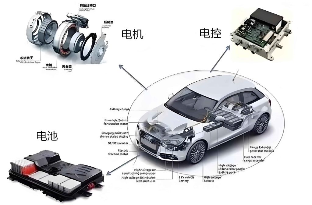
This image illustrates the Motor Control Unit in context, highlighting its integration within the ECS. The Motor Control Unit is central to powertrain performance, and its reliability directly impacts vehicle efficiency. As I delve deeper, it’s clear that the Motor Control Unit’s role extends beyond basic control to encompass energy optimization and safety functions.
Fault Types in the NEV Electronic Control System
Faults in the ECS can be categorized into hardware, software, and communication failures. Each type poses unique challenges for diagnosis and repair. I analyze these below, with tables to summarize examples and impacts.
Hardware faults involve physical components such as power modules, sensors, control units, and wiring harnesses. These can lead to system malfunctions or safety hazards. For instance, a faulty Motor Control Unit may cause erratic torque output, while sensor failures can mislead the VCU. Common hardware issues include short circuits, open circuits, and component degradation. The failure rate \( \lambda \) of hardware components often follows an exponential distribution:
$$ \lambda(t) = \lambda_0 e^{-\beta t} $$
where \( \lambda_0 \) is initial failure rate and \( \beta \) is decay constant. Regular inspection is vital to mitigate these risks.
Software faults arise from errors in program code, such as bugs, incompatibilities, or incorrect data inputs. These can disrupt algorithms for energy management or motor control, affecting range and performance. For example, a bug in the Motor Control Unit’s firmware might cause incorrect PWM signal generation, leading to motor stalling. Software reliability can be modeled using metrics like mean time between failures (MTBF):
$$ MTBF = \frac{T_{total}}{N_{faults}} $$
where \( T_{total} \) is total operation time and \( N_{faults} \) is number of faults.
Communication faults occur when data exchange between ECS components fails, often due to issues with protocols like Controller Area Network (CAN) or Local Interconnect Network (LIN). This can cause coordination losses, such as the VCU not receiving signals from the Motor Control Unit. The error probability \( P_e \) in communication can be expressed as:
$$ P_e = 1 – e^{-\lambda_c t} $$
where \( \lambda_c \) is communication error rate. The following table categorizes fault types with examples:
| Fault Type | Examples | Potential Impact |
|---|---|---|
| Hardware Faults | Power module failure, sensor damage, wiring corrosion | System shutdown, safety risks |
| Software Faults | Algorithm errors, update failures, data corruption | Reduced efficiency, false alarms |
| Communication Faults | CAN bus errors, signal interference, protocol mismatches | Loss of coordination, erratic behavior |
Fault Diagnosis Methods for the NEV Electronic Control System
Effective diagnosis relies on multiple methods to identify and localize faults. I discuss four primary approaches: fault code reading, data stream monitoring, functional testing, and visual inspection. These methods are often combined for comprehensive analysis.
Fault code reading utilizes the On-Board Diagnostics (OBD) system, which generates diagnostic trouble codes (DTCs) when anomalies are detected. By connecting a scan tool to the OBD port, technicians can retrieve codes that indicate issues in components like the Motor Control Unit. However, interpretation requires expertise to distinguish genuine faults from transient errors. The probability of a true fault given a DTC \( P(F|D) \) can be estimated using Bayes’ theorem:
$$ P(F|D) = \frac{P(D|F) P(F)}{P(D)} $$
where \( P(D|F) \) is likelihood of DTC given fault, \( P(F) \) is prior fault probability, and \( P(D) \) is total DTC probability.
Data stream monitoring involves real-time tracking of key parameters such as voltage, current, temperature, and torque. Deviations from normal ranges signal potential faults. For instance, abnormal current readings from the Motor Control Unit may indicate a failing power transistor. Data streams can be analyzed statistically; for example, the mean \( \mu \) and standard deviation \( \sigma \) of a parameter \( x \) over time \( t \):
$$ \mu = \frac{1}{n} \sum_{i=1}^n x_i, \quad \sigma = \sqrt{\frac{1}{n} \sum_{i=1}^n (x_i – \mu)^2} $$
Thresholds like \( \mu \pm 2\sigma \) can flag anomalies. The table below compares diagnostic methods:
| Method | Description | Advantages | Limitations |
|---|---|---|---|
| Fault Code Reading | Retrieves OBD-generated codes | Quick identification, standardized | May include false positives, requires interpretation |
| Data Stream Monitoring | Real-time parameter tracking | Detects subtle anomalies, proactive | Requires baseline data, can be data-intensive |
| Functional Testing | Tests specific modules under controlled conditions | Direct validation, comprehensive | Time-consuming, needs specialized equipment |
| Visual Inspection | Physical examination of components | Simple, cost-effective, detects obvious damage | Limited to surface issues, subjective |
Functional testing entails verifying each ECS module’s performance. For the Motor Control Unit, dynamic tests simulate driving scenarios like acceleration and braking to assess response accuracy. The motor’s torque response \( T_{response} \) should match commanded torque \( T_{cmd} \), with error \( \epsilon \):
$$ \epsilon = | T_{response} – T_{cmd} | $$
If \( \epsilon \) exceeds a tolerance, say 5%, the Motor Control Unit may be faulty. Similarly, BMS testing involves checking charge/discharge control and thermal management functions.
Visual inspection, though traditional, remains valuable for spotting physical damage such as corrosion or loose connections in the Motor Control Unit wiring. It complements technical methods by addressing environmental wear and tear.
Maintenance Strategies for the NEV Electronic Control System
To ensure ECS reliability, I propose a combination of preventive and corrective maintenance strategies, emphasizing the use of genuine parts and technician training. These strategies aim to minimize downtime and enhance safety.
Preventive maintenance involves regular checks and updates to avert faults. Key actions include inspecting the VCU, Motor Control Unit, and BMS for signs of wear; updating software to patch bugs; and adapting to environmental conditions. The maintenance interval \( T_{maint} \) can be optimized using reliability-centered maintenance (RCM) principles, minimizing cost \( C_{total} \):
$$ C_{total} = C_{pm} + C_{cm} + C_{downtime} $$
where \( C_{pm} \) is preventive maintenance cost, \( C_{cm} \) is corrective maintenance cost, and \( C_{downtime} \) is downtime cost. Scheduled updates for the Motor Control Unit firmware, for example, can prevent software glitches. A maintenance schedule table is provided:
| Component | Inspection Frequency | Key Actions | Tools Required |
|---|---|---|---|
| Motor Control Unit | Every 6 months or 10,000 km | Check connections, update firmware, test torque response | Diagnostic scanner, oscilloscope |
| Battery Management System | Every 3 months or 5,000 km | Monitor SOC, balance cells, inspect cooling | Battery tester, thermal camera |
| Vehicle Control Unit | Annually or 20,000 km | Verify algorithms, scan for errors, update software | VCU programmer, data logger |
Corrective maintenance addresses faults after they occur. For software issues, this may involve reprogramming the Motor Control Unit or reinstalling control algorithms. For hardware faults, technicians must safely replace components like damaged sensors or faulty Motor Control Unit modules. Safety is paramount due to high-voltage risks; insulation resistance \( R_{ins} \) should be checked:
$$ R_{ins} > \frac{V_{system}}{I_{leakage}} $$
where \( V_{system} \) is system voltage and \( I_{leakage} \) is permissible leakage current. Post-repair testing ensures functionality, often using dynamometer tests for the Motor Control Unit.
Using genuine original equipment manufacturer (OEM) parts is crucial for compatibility and performance. Non-OEM parts may save costs initially but can lead to higher failure rates and void warranties. The reliability \( R(t) \) of OEM vs. aftermarket parts can be compared using Weibull distribution:
$$ R(t) = e^{-(t/\alpha)^\beta} $$
where \( \alpha \) is scale parameter and \( \beta \) is shape parameter. OEM parts typically have higher \( \beta \), indicating longer life.
Technician training must evolve with technology. Regular workshops on the latest Motor Control Unit diagnostics and tools are essential. Training effectiveness can be measured by improved diagnostic accuracy \( A_d \):
$$ A_d = \frac{N_{correct}}{N_{total}} \times 100\% $$
where \( N_{correct} \) is number of correct diagnoses and \( N_{total} \) is total cases. Investing in training reduces misdiagnoses and enhances repair quality.
Conclusion
In summary, the electronic control system is fundamental to new energy vehicles, and its stability ensures safe operation. Components like the VCU, Motor Control Unit, and BMS require diligent monitoring. Faults, whether hardware, software, or communication-related, can be diagnosed through methods like OBD code reading and data stream analysis. Maintenance strategies should blend preventive and corrective approaches, prioritize OEM parts, and involve continuous technician education. As NEV technology advances, the Motor Control Unit will remain a focal point for innovation and reliability. Through proactive research and practice, we can support the sustainable growth of the NEV industry, enhancing vehicle performance and safety for users worldwide.
Throughout this discussion, I have emphasized the Motor Control Unit’s role in powertrain control and energy efficiency. By integrating formulas, such as those for torque control and efficiency, and tables summarizing parameters and methods, we gain a comprehensive understanding of ECS dynamics. The image inserted earlier visually reinforces the importance of the Motor Control Unit in the system architecture. Moving forward, further studies could explore advanced diagnostic algorithms or predictive maintenance models for the Motor Control Unit, leveraging artificial intelligence to preempt failures. Ultimately, a robust ECS is key to realizing the full potential of new energy vehicles in the global transportation landscape.