
In the evolution of hybrid car technology, a particularly interesting configuration emerged around 2020, primarily in certain SUV models. This architecture, often termed a P2.5 or electric Rear Axle Drive (eRAD) Plug-in Hybrid Electric Vehicle (PHEV), represents a sophisticated blend of conventional and electric propulsion. In this hybrid car system, the front wheels are driven by an internal combustion engine (ICE) coupled with a traditional multi-speed automatic transmission, while the rear wheels are powered solely by a dedicated electric motor. This approach effectively creates an on-demand all-wheel-drive (AWD) system without the need for mechanical transfer cases or complex power distribution units. The operation is managed by a network of control modules that seamlessly orchestrate the power sources for optimal performance, efficiency, and traction.
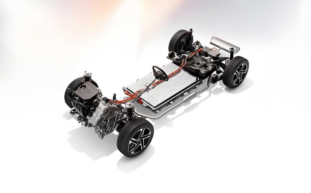
The core philosophy of this hybrid car design is decoupling. The internal combustion engine and the electric drive unit operate on separate axles. This decoupling allows for very flexible driving modes. The front axle, with its engine and transmission, handles high-speed cruising efficiently. The rear axle, with its instantly responsive electric motor, provides electric launch, torque filling during acceleration, and pure electric driving for shorter trips. Furthermore, this arrangement is perfect for implementing regenerative braking at the rear axle, recapturing energy that would otherwise be lost as heat. This specific hybrid car setup we are discussing typically features a 1.5L gasoline engine on the front axle and an ~85 kW electric motor on the rear, powered by a high-voltage (HV) battery pack of approximately 11-15 kWh, enabling a significant electric-only range.
High-Voltage System Core Components
The functionality of this advanced hybrid car hinges on its high-voltage (HV) electrical system. This system is responsible for storing energy, powering the electric drivetrain, and supporting auxiliary functions. Understanding each component is crucial for grasping how this hybrid car operates.
1. High-Voltage (HV) Battery Pack
The HV battery is the energy reservoir for the electric side of this hybrid car. It is a complex assembly not just of cells, but of integrated control and safety hardware.
- Construction: The pack is built from several modules connected in series. For instance, a pack with a nominal voltage of ~304 V might consist of 7 modules, each containing 12 individual Li-ion cells, yielding a module voltage of $$V_{module} = 12 \times V_{cell}$$ and a total pack voltage of $$V_{pack} = 7 \times V_{module}$$. The operational voltage window typically spans from a minimum of ~220 V to a maximum of ~350 V.
- Battery Electrical Module (BEM): This is the critical subsystem housed within the battery pack. It contains:
- Contactors: Main positive and negative relays that connect the battery to the rest of the HV system. A pre-charge contactor and resistor are also present to safely charge downstream capacitance before closing the main contactors, preventing damaging inrush currents. The sequence is:
- Pre-charge contactor closes.
- Main positive contactor closes.
- System self-test completes.
- Main negative contactor closes.
- Pre-charge contactor opens.
- Current Sensors: Both Hall-effect (on positive side) and shunt-type (on negative side) sensors are used to precisely measure current flow in and out of the pack. Discrepancies between these readings can indicate a fault.
- Fuses: The pack contains fuses for specific output circuits (e.g., 175A for the Belt-Integrated Starter Generator circuit, 125A for auxiliary HV components). The main safety disconnect, often called the Manual Service Disconnect (MSD), contains a high-amperage fuse (e.g., 250A) and physically breaks the positive HV circuit when removed.
- Contactors: Main positive and negative relays that connect the battery to the rest of the HV system. A pre-charge contactor and resistor are also present to safely charge downstream capacitance before closing the main contactors, preventing damaging inrush currents. The sequence is:
- Battery Energy Control Module (BECM): This is the brain of the battery pack. It continuously monitors:
- Individual cell voltages and temperatures.
- Total pack current and state of charge (SOC).
- Insulation resistance between the HV circuits and the vehicle chassis to detect potential ground faults.
The BECM performs cell balancing to maintain uniformity and communicates with other vehicle controllers via a High-Speed CAN bus.
| Parameter | Specification |
|---|---|
| Total Nominal Voltage | ~304 V |
| Capacity | ~11 – 15 kWh |
| Usable SOC Window | e.g., 20% – 95% |
| Continuous Discharge Power | ~47 kW |
| Number of Modules / Cells | e.g., 7 modules / 84 cells |
| Main Circuit Protection | 250A Fuse (in MSD) |
2. High-Voltage Junction Box (HVJB) & Power Conversion
This unit is the central hub for power distribution and conversion in this hybrid car. It integrates several key functions into one assembly.
- Battery Charger Control Module (BCCM): Manages all charging functions.
- AC Charging: Contains an onboard charger (OBC, e.g., 7 kW) that converts grid AC to HV DC for the battery.
- DC Fast Charging: Includes a high-current contactor (e.g., 100A capable) to directly route power from a DC fast-charging station to the battery.
- DC/DC Converter: This is the heart of the 12V electrical system in this hybrid car. It steps down the HV battery voltage (e.g., ~300V) to a regulated ~13.2V to:
- Power all standard 12V vehicle loads (lights, infotainment, ECUs).
- Charge the 12V auxiliary/starting battery.
Its power output (e.g., 3.8 kW) is significantly higher than a traditional alternator, supporting heavier electrical loads. The formula for its (ideal) power transfer is: $$P_{12V} \approx \eta \cdot P_{HV}$$ where $\eta$ is the conversion efficiency.
- Power Distribution: The HVJB houses fuses and connectors that distribute HV power to other auxiliary components, such as:
- Electric Air Conditioning (eA/C) Compressor.
- High-Voltage Coolant Heater (HVCH).
3. Electric Rear Axle Drive (eRAD)
This is the defining component of this hybrid car architecture. The eRAD is a fully integrated unit replacing the conventional rear differential, driveshaft, and brake-based torque vectoring system.
- Assembly: It combines a permanent magnet synchronous motor (PMSM), a power inverter (EPIC), a single-speed reduction gearset, and an open differential into a single housing.
- Motor & Inverter: The inverter, mounted directly to the eRAD assembly, performs two key roles:
- Drive Mode: Converts HV DC from the battery into three-phase AC for the motor. The inverter precisely controls the phase and frequency of this AC based on torque commands from the Powertrain Control Module (PCM) and motor position feedback from a resolver. The motor’s torque output is a function of current: $$T_{motor} = k_t \cdot I$$ where $k_t$ is the motor’s torque constant.
- Regeneration Mode: Acts as a controlled rectifier. When the hybrid car is braking or coasting, the motor acts as a generator, producing three-phase AC. The inverter converts this AC back to DC, regulates its voltage, and feeds it back to the HV battery. The regenerative braking force is precisely controlled by the inverter.
- Driveline Disconnect: A critical mechanical feature within the eRAD is a dog clutch system that can physically disconnect the electric motor from the differential and rear wheels. This is typically activated at high speeds (e.g., > 145 km/h) to prevent the motor from being dragged at excessively high RPM, improving efficiency. An actuator and position sensor manage this function.
| Component | Primary Function | Key Sub-Components / Notes |
|---|---|---|
| HV Battery Pack | Energy Storage | Cell modules, BECM, Contactors, Pre-charge circuit, Fuses, Current/Voltage/Temp Sensors, MSD. |
| HV Junction Box (HVJB) | Power Distribution & Conversion | BCCM (OBC & DC Charging), DC/DC Converter, Distribution Fuses for eA/C & Heater. |
| Electric Rear Axle Drive (eRAD) | Rear Wheel Propulsion & Regeneration | PMSM, Inverter (EPIC), Reduction Gear, Differential, Driveline Disconnect Clutch. |
| Belt-Integrated Starter Generator (BISG) | Engine Starting, Mild Generation, Torque Assist | Motor/Generator on engine front end, Dedicated Inverter (EPICB). |
Operational Modes and Torque Management
The true intelligence of this hybrid car is showcased in its seamless transition between various operational modes. The driver can select a preferred mode, but the vehicle’s controllers will always override to protect components or meet driver demand.
| Mode | Energy Priority | ICE Status | eRAD Status | Typical Use Case |
|---|---|---|---|---|
| EV (Electric Vehicle) | Maximize battery use | Off unless high power demanded | Active (Primary drive) | City driving, short trips, low noise/emissions operation. |
| Hybrid (Default) | Optimize overall efficiency | Automatically managed (On/Off) | Automatically managed | General driving. System decides best combination. |
| Save / Battery Hold | Preserve current battery SOC | Primary source for propulsion | Used for boost and regeneration only | Highway driving, reserving battery charge for later city EV use. |
Beyond driver selection, the hybrid car’s control system (primarily the PCM) is constantly calculating the optimal torque split. The total torque requested by the driver via the accelerator pedal is met by a combination of sources:
$$T_{total\_requested} = T_{ice} + T_{erad} + T_{bisg}$$
Where $T_{ice}$ is engine torque, $T_{erad}$ is rear electric motor torque, and $T_{bisg}$ is the torque from the belt-starter generator (which can provide a small assist or load to the engine).
The control strategy considers multiple inputs:
$$Mode_{strategy} = f(SOC, T_{req}, V_{vehicle}, \theta_{pedal}, T_{battery}, T_{ice}, Mode_{driver})$$
Factors like battery state of charge (SOC), battery temperature, engine temperature, and wheel slip are all fed into the algorithm to determine the most efficient, responsive, or stable torque distribution. For example, during hard acceleration, the hybrid car might use both engine and eRAD for maximum thrust (“boost” mode). During steady cruising, it may use only the engine. During deceleration, it maximizes regeneration at the eRAD.
Diagnostic and Safety Considerations for the Hybrid Car
Working on such a hybrid car requires strict adherence to high-voltage safety protocols. The system is designed with multiple layers of protection, but proper procedure is non-negotiable.
- De-energization Procedure: Before any mechanical work near HV components, the system must be made safe. This involves:
- Turning the vehicle to OFF and securing the key/fob away.
- Disconnecting the 12V auxiliary battery (negative terminal first).
- Waiting the specified time (often 5-10 minutes) for capacitors to discharge.
- Verifying the HV system is de-energized using a certified CAT III/IV multimeter by measuring:
- Voltage between terminals at known points (e.g., motor inverter terminals). Target: < 60 V DC.
- Voltage between each HV terminal and the chassis. Target: < 60 V DC.
- Physically removing the Manual Service Disconnect (MSD) from the HV battery pack and keeping it in the technician’s possession.
- Insulation Faults: A common diagnostic trouble code (DTC) in a hybrid car relates to insulation resistance. The BECM periodically tests the resistance between the HV+ and chassis, and HV- and chassis. If resistance falls below a threshold (e.g., < 1 MΩ), a fault is set. Diagnosis involves:
- Isolating the HV system by disconnecting components.
- Using a megaohmmeter (insulation tester) to measure resistance on each branch of the circuit.
- Locating the component (battery, cable, motor, compressor, heater) with degraded insulation, often due to moisture ingress or physical damage.
- Cooling Systems: Both the HV battery and the eRAD/inverter have dedicated cooling circuits (liquid-cooled). Faults in these systems (pump failures, leaks, sensor issues) can lead to power limitation or system shutdown to prevent overheating, which is a critical failure mode for the hybrid car’s performance and battery life.
- Communication Networks: The proper function of the hybrid car depends on flawless communication between the PCM, BECM, Inverters (EPIC/EPICB), and DC/DC converter via CAN and/or FlexRay buses. Diagnosis often starts with verifying network integrity and checking for module communication DTCs.
| Symptom / DTC Category | Potential Causes | Initial Diagnostic Steps |
|---|---|---|
| Hybrid System Warning / Reduced Power | Battery Over-temperature, Insulation Fault, Coolant Pump Failure, High-voltage Contactor Fault. | 1. Scan for codes in all relevant modules (PCM, BECM, EPIC). 2. Check HV coolant pump operation and coolant level. 3. View live data for battery/component temperatures and contactor status. |
| No EV Mode / Engine Runs Constantly | Low HV Battery SOC, Battery Fault (Cell Imbalance, Voltage), eRAD Inverter or Motor Fault, Driver Mode Selection Error. | 1. Verify actual HV battery SOC via scan tool. 2. Check for battery-related DTCs and cell voltage deviation. 3. Test for communication with eRAD inverter and check its power/ground supplies. |
| Charging Fault (AC or DC) | Faulty EVSE, Damaged Charging Port, BCCM Failure, HVJB Issue, HV Battery Isolation Fault. | 1. Try a different known-good charging station. 2. Inspect charging port for damage/burnt pins. 3. Scan BCCM for specific charging fault codes. 4. Check for system insulation faults. |
In conclusion, the eRAD P2.5 plug-in hybrid car architecture is a compelling solution that delivers the benefits of electrification—instant torque, zero-emission driving, and regenerative braking—while leveraging the long-range and refueling convenience of an internal combustion engine. Its unique layout, with a traditional front powertrain and an electrically driven rear axle, provides inherent all-wheel-drive capability and great packaging flexibility. The system’s complexity, centered around a high-voltage network of intelligent components like the HV battery with its BECM, the multi-function HVJB, and the integrated eRAD unit, requires a deep understanding of both electrical and mechanical systems for effective diagnosis and repair. As hybrid car technology continues to evolve, architectures like this demonstrate a practical and powerful step towards full electrification.