
As a key tool in promoting green transportation, the efficiency and reliability of the motor control system in new energy vehicles directly impact vehicle performance and user experience. Improving motor efficiency is crucial for enhancing energy utilization, maintaining system stability, and preventing faults. In this article, I will explore maintenance technologies for the motor control system based on motor efficiency, which can facilitate early fault warnings and precise repairs, improve the overall operational economy and safety, and drive the sustainable development of the new energy vehicle industry. Motor efficiency serves as a critical indicator for measuring the ability of a vehicle’s motor to convert electrical energy into mechanical energy, directly linking to driving range and power performance. With the rapid advancement of new energy vehicle technology, enhancing motor efficiency has become a core aspect of improving overall vehicle performance and reducing energy consumption. Motor efficiency not only reflects the motor’s operational status but also indicates the collaborative effectiveness of the entire motor control unit. By monitoring and adjusting the motor’s operating state to ensure it runs within the optimal efficiency range, the comprehensive operational performance of the vehicle can be enhanced. Changes in motor efficiency often serve as precursors to faults in the motor control unit; thus, precise assessment of motor efficiency can enable preemptive alerts for system anomalies, preventing fault escalation. The stability of motor efficiency imposes higher demands on the motor control unit, pushing maintenance technologies toward more intelligent and refined approaches. As a key performance metric, motor efficiency influences various aspects of the motor control unit, including power output, energy management, and fault diagnosis, making it essential for ensuring efficient and safe vehicle operation.
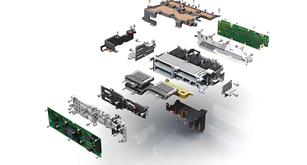
The motor control system in new energy vehicles primarily consists of the motor control unit, power drive module, sensors, and actuators. The motor control unit typically employs high-performance microprocessors with operating frequencies ranging from 100 to 300 MHz, responsible for signal processing, strategy computation, and system coordination. The power drive module includes inverters and DC converters, with current output ranges from 100 to 5,000 A, enabling precise motor speed control and power conversion. Sensors encompass speed sensors, current-voltage sensors, and temperature sensors, which collectively monitor operational parameters to ensure optimal performance. The integration of these components allows the motor control unit to manage energy flow efficiently, contributing to overall vehicle efficiency. For instance, the motor control unit continuously adjusts power output based on real-time data from sensors, optimizing motor efficiency under varying load conditions. This dynamic coordination highlights the importance of a well-structured motor control unit in maintaining system reliability. Moreover, advancements in semiconductor technology have enabled more compact and powerful motor control units, further enhancing their role in vehicle electrification. As I delve deeper into this topic, I will emphasize how the motor control unit serves as the brain of the system, orchestrating all functions to maximize motor efficiency and ensure smooth operation.
Common faults in the motor control system can be categorized into issues with the motor control unit, power drive module, and signal acquisition with sensors. For the motor control unit, typical faults include data processing delays, signal loss, and logic errors, which may lead to software deadlocks or memory unit damage, resulting in control strategy failure and unstable vehicle power output. When the motor control unit malfunctions, it can prolong response times for various vehicle operations, adversely affecting acceleration capabilities and overall safety. Communication signal interruptions are a classic fault in the motor control unit, impairing effective control of vehicle power and potentially reducing energy recovery efficiency, thereby shortening driving range and diminishing user experience. In severe cases, such faults can cause complete system paralysis. Without timely diagnosis and maintenance during long-term operation, fault accumulation may occur, leading to overheating of power devices, abnormal control algorithms, and even failure of core components, exacerbating repair costs and posing safety risks. These issues underscore the critical role of the motor control unit in ensuring system stability under complex road conditions and extreme climates.
Faults in the power drive module often manifest as device aging, short circuits, and overheating. Overheating can cause temperatures to exceed 120°C, triggering thermal runaway and component failure. Abnormal current fluctuations, typically in the range of 100 to 500 Hz, accompany module faults, leading to reduced motor output power and decreased vehicle range. Additionally, power drive module anomalies can induce electromagnetic interference, disrupting the stable operation of other electronic devices in the vehicle. Under high-load or prolonged operation, if such faults are not controlled promptly, they can accelerate device degradation and affect the normal functioning of the motor control unit and battery management system, causing frequent activation of protection mechanisms and interrupting continuous power output. This highlights the interdependence between the power drive module and the motor control unit, where faults in one can cascade to the other, emphasizing the need for integrated maintenance approaches.
Sensor faults include signal drift, poor contact, or response delays, resulting in distorted data acquisition. Sensors are designed to operate in environments ranging from -40°C to 85°C; temperature fluctuations outside this range can cause measurement deviations. Sensor faults interfere with the accurate assessment of motor efficiency, leading to失效 of the motor control unit’s adjustment mechanisms and affecting overall vehicle performance stability. Abnormal sensor signals may also cause erroneous judgments by the control system, resulting in power output fluctuations or improper activation of protection mechanisms, compromising driving experience and safety. This further stresses the importance of reliable sensor data for the motor control unit to execute precise control strategies. As I analyze these faults, it becomes evident that a holistic view of the motor control unit and its peripherals is essential for effective maintenance.
To address these challenges, I propose maintenance technologies based on motor efficiency, focusing on intelligent diagnosis for the motor control unit, optimized repair processes for the power drive module, and adaptive control mechanisms for sensors. First, the intelligent diagnosis strategy for the motor control unit relies on building a high-precision motor efficiency model. This model dynamically reflects the impact of motor load, speed, and current changes on system performance. By monitoring the processing speed and data stream integrity of the motor control unit alongside efficiency parameters, the diagnosis system can detect potential software and hardware faults, reducing misdiagnosis rates and improving repair accuracy. Incorporating machine learning techniques enhances the system’s intelligence and adaptability, facilitating fault prediction and maintenance efficiency. The motor efficiency model can be expressed using the following formula, where efficiency (η) is a function of various operational parameters:
$$\eta = f(P_{load}, \omega, I) = \frac{P_{mech}}{P_{elec}}$$
Here, \(P_{load}\) represents the motor load in Newton-meters (N·m), \(\omega\) denotes the rotational speed in revolutions per minute (rpm), and \(I\) is the current in amperes (A). \(P_{mech}\) is the mechanical output power, and \(P_{elec}\) is the electrical input power. This formula helps quantify how changes in these parameters affect motor efficiency, providing a basis for the motor control unit to optimize performance. For the diagnosis system, key parameters must be monitored in real-time, as summarized in the table below:
| Parameter | Technical Requirement | Remarks |
|---|---|---|
| Operating Temperature Range (°C) | -20 to 50 | Adapts to various environmental conditions |
| Diagnostic Computation Delay (ms) | ≤10 | Ensures real-time performance |
| Motor Load Range (N·m) | 0 to 500 | Reflects impact of load on motor efficiency |
| Speed Range (rpm) | 0 to 8,000 | Monitors motor efficiency changes at different speeds |
| Current Measurement Range (A) | 0 to 500 | Supports multiple driving conditions |
| Fault Warning Accuracy (%) | ≥92 | Reduces misdiagnosis rate |
| Data Stream Integrity Monitoring Frequency (Hz) | 1,000 | Enables real-time data acquisition |
| Fault Type Coverage | Software anomalies, hardware faults, communication errors | Facilitates multi-mode fault identification |
This table outlines the critical metrics for the intelligent diagnosis system, emphasizing the role of the motor control unit in maintaining these standards. In practice, a new energy vehicle company developed a smart diagnosis platform that integrates multi-dimensional efficiency data with motor control unit parameters, effectively capturing control logic errors and communication delays. This platform reduces fault response time and supports wide-temperature environments, enhancing fault detection sensitivity and system reliability. The continuous optimization of its algorithms allows adaptation to different vehicle models and complex conditions, mitigating performance fluctuations caused by motor control unit faults and promoting intelligent maintenance processes.
Second, the repair process optimization and efficiency compensation method for the power drive module focus on thermal management, component replacement, and parameter calibration. The goal is to ensure stable operation within a current range of 100 to 5,000 A. Efficiency compensation involves adjusting inverter switching frequencies (typically 100 to 500 Hz) and optimizing PWM waveforms to minimize power transmission losses. The compensation algorithm can be enhanced using real-time data, improving module stability and reliability. The repair process requires stringent temperature control from -40°C to 120°C, with wind speeds of 10 to 15 m/s for cooling, and aims to shorten repair cycles to 10-12 hours. Effective thermal management prevents thermal stress-induced aging and performance degradation, maintaining continuous power output. Parameter calibration fine-tunes control signals to match the power module with the overall motor control unit, avoiding energy waste and overload risks. The efficiency compensation can be modeled as:
$$\Delta \eta = g(f_{sw}, D)$$
Where \(\Delta \eta\) represents the efficiency improvement, \(f_{sw}\) is the switching frequency in Hz, and \(D\) is the duty cycle of the PWM signal. By optimizing these variables, the motor control unit can compensate for losses in the power drive module. A technical team developed a repair optimization scheme incorporating dynamic efficiency compensation algorithms, which mitigate thermal runaway caused by module aging. This scheme enables intelligent adjustment of thermal management parameters, improving module stability and vehicle range, while providing a standardized operational workflow. Additionally, it integrates fault trend prediction, helping maintenance personnel identify potential issues early and reduce unplanned vehicle downtime.
Third, the efficiency adaptive control mechanism enhances sensor fault tolerance through redundant designs and multi-sensor fusion techniques. This mechanism maintains signal continuity and accuracy by automatically compensating for sensor drift and response delays. The control system employs redundant sensor layouts and data fusion algorithms, operating effectively in environments from -40°C to 85°C. By modifying sampling frequencies and signal filtering parameters, it improves data real-time performance and stability. Incorporating artificial intelligence further boosts the system’s fault prediction and diagnosis capabilities, ensuring precise control and rapid response. The adaptive mechanism uses a multi-level fault-tolerant architecture, allowing the motor control unit to detect sensor anomalies in real-time and switch to backup sensors or derive valid data through algorithms, ensuring that motor efficiency monitoring remains unaffected by single-point failures. This significantly enhances the robustness and reliability of the entire motor control unit, maintaining vehicle stability in complex environments. The data fusion process can be expressed as:
$$S_{fused} = \sum_{i=1}^{n} w_i S_i$$
Where \(S_{fused}\) is the fused sensor signal, \(S_i\) represents individual sensor readings, and \(w_i\) are weights assigned based on sensor reliability, often adjusted by the motor control unit using adaptive algorithms. A new energy vehicle manufacturer successfully applied this multi-layer fault-tolerant and efficiency adaptive control strategy. By aggregating data from multiple sensors, the system maintains accurate motor efficiency assessment even when a single sensor fails, automatically adjusting control parameters to ensure smooth motor output. This design considers stable operation in harsh environments, increasing vehicle safety and durability while reducing sensor fault repair frequency and costs. The control strategy continuously learns and adapts to varying conditions, driving the motor control unit toward greater intelligence and reliability.
In conclusion, improving motor efficiency is vital for ensuring the reliability of the motor control unit in new energy vehicles. As technology advances, the complexity and intelligence of the motor control unit will continue to grow, making precise monitoring and intelligent diagnosis based on motor efficiency a core reliance. By integrating big data analytics, artificial intelligence, and the Internet of Things, real-time adaptive adjustment and fault prevention can be achieved, pushing maintenance technologies toward proactive and intelligent directions. In the future, the industry should focus on standardization and cross-domain collaboration to foster an efficient, green, and sustainable maintenance ecosystem for new energy vehicles, contributing to carbon neutrality goals and accelerating the evolution of intelligent transportation systems. Throughout this discussion, I have emphasized the centrality of the motor control unit in orchestrating these advancements, underscoring its role as the linchpin for optimizing motor efficiency and ensuring long-term system health. The motor control unit, through continuous innovation, will remain at the forefront of enabling smarter, more reliable vehicles that meet the demands of a greener future.