
The evolution of battery technology has fundamentally transformed the landscape of underground mining equipment. Heavy-duty battery-powered support carriers, replacing their diesel counterparts, have become central to modern, efficient, and environmentally conscious mining operations. The core of these vehicles’ performance—encompassing traction, gradeability, maneuverability, and overall energy efficiency—is determined by their electric drive system. The design and configuration of this system are critical, as they must reconcile often conflicting demands: delivering immense torque for moving multi-ton loads in confined, uneven roadways while maximizing the limited energy stored in onboard battery packs. This article delves into the key technologies underpinning the electric drive system of modern heavy-duty support carriers, analyzing prevalent architectures, their control paradigms, and the engineering trade-offs involved.
An electric drive system for such vehicles is more than just a motor replacing an engine. It is an integrated electromechanical system responsible for converting stored electrical energy into controlled motion. Its primary components include the traction motor(s), power electronic controllers (inverters), the gear reduction unit(s), and the final drive mechanism that connects to the wheels. The choice of architecture—how these components are arranged and interconnected—defines the vehicle’s dynamic capabilities and limitations. The central challenge lies in managing wheel slip, distributing torque effectively across axles and wheels, and ensuring reliable operation under harsh mining conditions, all while optimizing the use of every kilowatt-hour from the battery.
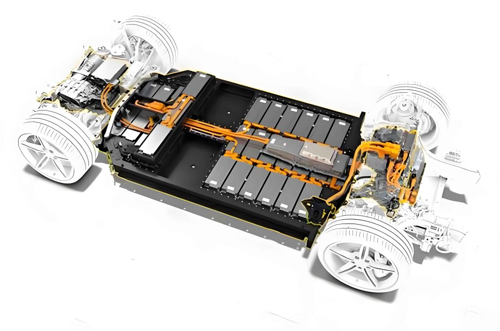
Historically, designs have evolved from simple, centralized drives to more sophisticated distributed configurations. We can categorize the primary architectures for heavy-duty support carrier electric drive systems into four distinct types, each with its own set of advantages and complexities.
1. Centralized Single-Motor Axle Drive
This architecture represents the most direct translation from a conventional mechanical powertrain. A single high-power traction motor outputs torque to a central mechanical transmission or a simple reducer. This output is then split via a transfer case to drive shafts connected to both the front and rear axles, which contain traditional mechanical differentials.
System Dynamics: The vehicle’s motion is governed by the fundamental road load equation. The total tractive effort $F_{te}$ required must overcome the resistive forces: rolling resistance $F_{rr}$, gradient resistance $F_{grad}$, and inertial force $F_{inertia}$ during acceleration.
$$F_{te} = F_{rr} + F_{grad} + F_{inertia} = mgf_r \cos(\theta) + mg \sin(\theta) + m \frac{dv}{dt}$$
where $m$ is the vehicle mass, $g$ is gravity, $f_r$ is the coefficient of rolling resistance, $\theta$ is the grade angle, and $v$ is velocity. The single motor must supply the torque $T_m$ to generate this effort at the wheels:
$$T_m = \frac{F_{te} \cdot r_w}{i_g \cdot i_d \cdot \eta_{drivetrain}}$$
Here, $r_w$ is the wheel radius, $i_g$ is the gearbox ratio, $i_d$ is the final drive (differential) ratio, and $\eta_{drivetrain}$ is the aggregate mechanical efficiency.
Key Limitation – Parasitic Power Loss: A major drawback in rigid-frame or poorly tuned articulated vehicles with this electric drive system is the potential for “torque wind-up” or parasitic power loss. When the front and rear axles are forced to rotate at exactly the same speed (due to the fixed-ratio mechanical coupling) but follow paths of slightly different lengths during a turn or on uneven ground, a conflict arises. This can lead to one axle driving while the other is effectively braked by the drivetrain itself, causing significant energy loss and component stress. The mechanical differentials only manage speed differences between wheels on the same axle, not between axles.
| Aspect | Description | Implication for Electric Drive System |
|---|---|---|
| Architecture | Single motor → Gearbox → Transfer Case → Drive Shafts → Axles with Diffs | Simple, resembles traditional layout. |
| Control Complexity | Low. Single motor controller. | Easier thermal and EMI management. |
| Torque Distribution | Fixed, mechanically determined (typically 50:50). | No adaptive control; prone to parasitic loss. |
| Fault Tolerance | Very Low. Motor failure disables the entire vehicle. | High risk of roadway blockage. |
| Efficiency | Lower due to multiple mechanical stages and potential parasitic loss. | Reduces effective range per battery charge. |
2. Dual-Motor, Dual-Axle Drive
This configuration decouples the front and rear drivetrains at the power source level. Two independent traction motors are used: one dedicated to driving the front axle (through a reducer) and the other driving the rear axle. This eliminates the need for a central transfer case and inter-axle drive shafts.
Control Advantages: This introduces a fundamental leap in controllability for the electric drive system. The torque to each axle, $T_{front}$ and $T_{rear}$, can now be independently and dynamically controlled by their respective inverters. The total tractive effort becomes the sum of the efforts from each axle:
$$F_{te} = F_{te,front} + F_{te,rear} = \frac{T_{front} \cdot i_{front} \cdot \eta_{front}}{r_w} + \frac{T_{rear} \cdot i_{rear} \cdot \eta_{rear}}{r_w}$$
A basic torque distribution strategy can aim to minimize total losses or prevent axle slip. For instance, a load-proportional distribution might set:
$$T_{front} = k \cdot T_{total}, \quad T_{rear} = (1-k) \cdot T_{total}$$
where $k$ is a distribution factor often based on static weight distribution or dynamic load transfer. More advanced strategies can use axle speed feedback to detect slip and reduce torque to the slipping axle.
Fault Tolerance: A significant operational benefit is partial functionality in case of a motor failure. If one motor fails, the other can often provide enough torque to limp the vehicle to a safe area, preventing a complete blockade—a critical feature in confined mine passages.
| Aspect | Description | Implication for Electric Drive System |
|---|---|---|
| Architecture | Independent Front Motor/Reducer/Axle & Rear Motor/Reducer/Axle | Decouples front/rear kinetics, removes transfer case. |
| Control Complexity | Medium. Requires coordination between two motor controllers. | Enables basic axle torque vectoring. |
| Torque Distribution | Dynamically adjustable between axles via software. | Can optimize traction, reduce slip, improve energy use. |
| Fault Tolerance | Medium. Vehicle may retain limited mobility with one failed drive unit. | Operational safety is enhanced. |
| Efficiency | Higher. Eliminates parasitic inter-axle loss; efficiency maps of two smaller motors can be better matched to load. | Potentially extends range. |
3. Four-Motor, Dual-Axle Drive (Dual-Motor Per Axle)
For the heaviest payloads exceeding 80 tons, even dual-motor systems may face challenges in delivering sufficient torque within package constraints. The four-motor architecture addresses this by further distributing power. Each axle is driven by two motors working in tandem, typically through a dual-input reduction gearbox that sums their torques before the mechanical differential.
Torque Summation and Control: The torque at each axle is the sum of the outputs from its two dedicated motors. For the front axle:
$$T_{axle,front} = T_{motor1} + T_{motor2}$$
$$F_{te,front} = \frac{T_{axle,front} \cdot i_{axle} \cdot \eta_{axle}}{r_w}$$
This configuration offers tremendous flexibility for the vehicle’s electric drive system. During light-load or high-speed travel, one motor per axle can be de-energized or operated at high efficiency points to conserve energy. Under maximum load or on severe gradients, all four motors can be engaged at optimal torque levels. This load-adaptive capability is a key efficiency driver.
Enhanced Traction Control: With independent control of each motor pair per axle, the system can more precisely manage wheel slip. If sensors indicate the beginning of slip on one side of an axle, the torque command to the corresponding motor pair can be momentarily reduced, leveraging the limited-slip effect of the mechanical differential. This provides a more robust electric drive system for low-adhesion surfaces common in mines.
| Aspect | Description | Implication for Electric Drive System |
|---|---|---|
| Architecture | Two motors per axle → Dual-input Gearbox → Axle with Diff. | Extreme torque capability; highly modular power. |
| Control Complexity | High. Requires synchronized control of four motors with axle-level strategies. | Enables sophisticated load-adaptation and efficiency optimization. |
| Torque Distribution | Adjustable at both inter-axle and intra-axle (motor pair) levels. | Superior traction management and failure mitigation. |
| Fault Tolerance | High. Can operate on reduced number of motors with graceful performance degradation. | Maximum operational availability. |
| Efficiency | Very High. Motors can operate near peak efficiency across a wider load spectrum. | Optimal energy usage, critical for battery runtime. |
4. Distributed Wheel-End Drive (e-Axle or In-Wheel Concepts)
This represents the most radical departure from conventional layouts. In a pure distributed electric drive system, each wheel is driven by its own dedicated motor, often integrated with a dedicated reduction gearbox (forming an “e-corner” module). This eliminates all mechanical differentials and drive shafts.
Electronic Differential and Advanced Dynamics: The mechanical differential’s function is replaced entirely by software in the Electronic Differential System (EDS). The core kinematic relationship for a turning vehicle is:
$$\omega_{out} = \omega_{in} \cdot (1 – \frac{B}{R}) \quad \text{and} \quad \omega_{in} = \omega_{in} \cdot (1 + \frac{B}{R})$$
where $\omega_{out}$ and $\omega_{in}$ are the angular speeds of the outer and inner wheels, $B$ is the track width, and $R$ is the turn radius. The vehicle’s master controller calculates the required speed for each wheel based on steering angle and vehicle speed, and commands each inverter/motor accordingly.
Torque Vectoring: This architecture enables true torque vectoring—independently controlling the magnitude and direction of torque at each wheel. This can generate direct yaw moments to aid vehicle stability and turning. The yaw moment $M_z$ generated by differential wheel forces is:
$$M_z = \frac{B}{2} (F_{x,rr} – F_{x,rl} + F_{x,fr} – F_{x,fl})$$
where $F_{x}$ is the longitudinal tire force at each wheel (rr=rear right, rl=rear left, etc.). This allows the electric drive system to actively correct understeer or oversteer tendencies.
Packaging and Efficiency: It saves significant space by removing central driveline components, allowing for more flexible vehicle design and potentially larger battery packs. It also eliminates efficiency losses associated with mechanical differentials and long drive shafts.
| Aspect | Description | Implication for Electric Drive System |
|---|---|---|
| Architecture | Individual motor + reducer per wheel (4 or 6 independent drives). | Maximum packaging freedom; no mechanical diffs or shafts. |
| Control Complexity | Very High. Requires high-fidelity vehicle dynamics model, EDS, and torque vectoring algorithms. | Peak controllability potential, but major software challenge. |
| Torque Distribution | Fully independent, down to individual wheel level. | Enables active stability control and optimal force allocation. |
| Fault Tolerance | Very High. Multiple drive failures can be accommodated by the remaining wheels. | Excellent redundancy. |
| Efficiency | Highest potential. Minimal mechanical loss paths; each motor can be optimized for its wheel load. | Theoretical peak for the electric drive system. |
In-Depth Analysis: The Four-Motor Drive System
Given its prevalence in the heaviest class of carriers, the four-motor electric drive system warrants a deeper technical examination. Its effectiveness hinges on two pillars: a robust control strategy and a well-understood dynamic model.
Control Strategy for Load Adaptation: A hierarchical controller is typically employed. The top layer determines the total torque demand $T_{req}$ based on the driver’s command (accelerator/brake) and vehicle state. This demand is then allocated optimally between the four motors. One optimization goal is to minimize total electrical losses $P_{loss,total}$.
$$P_{loss,total} = \sum_{i=1}^{4} P_{loss,i}(T_i, \omega_i)$$
$$\text{subject to: } \sum_{i=1}^{4} T_i \cdot i_{axle} = T_{req} \cdot r_w, \quad T_{i,min} \leq T_i \leq T_{i,max}$$
where $P_{loss,i}$ is the loss map of motor $i$, a function of its torque $T_i$ and speed $\omega_i$. This loss map includes copper losses, iron losses, and inverter switching losses. Solving this real-time optimization ensures the electric drive system operates at its global efficiency peak for any given demand.
Dynamic Modeling and Response: For a heavy articulated carrier, a simplified planar model is useful. The equations of motion for the front and rear modules (for an articulated vehicle) involve longitudinal, lateral, and yaw dynamics coupled at the articulation joint. The longitudinal dynamics for each module, powered by its respective motor pair, can be expressed as:
$$m_f \dot{v}_{x,f} = F_{x,f} – F_{drag,f} – F_{rr,f} – F_{couple,x}$$
$$m_r \dot{v}_{x,r} = F_{x,r} – F_{drag,r} – F_{rr,r} + F_{couple,x}$$
where $F_{x,f/r}$ is the tractive force from the wheel(s), and $F_{couple,x}$ is the longitudinal coupling force at the articulation joint. A key challenge noted in practice is that the response of such a high-inertia, compliant driveline to rapid torque commands from four motors can lead to oscillations or “shudder.” This is often modeled by including torsional compliance $k_{driveshaft}$ and damping $c_{driveshaft}$ in the driveline:
$$J_{motor} \dot{\omega}_m = T_m – k_{driveshaft}(\theta_m – \theta_w) – c_{driveshaft}(\omega_m – \omega_w)$$
$$J_{wheel} \dot{\omega}_w = k_{driveshaft}(\theta_m – \theta_w) + c_{driveshaft}(\omega_m – \omega_w) – T_{load}$$
Effective control of the electric drive system must include filters or model-based controllers to manage this compliance and ensure smooth torque delivery without excessive gearbox noise or wear.
System Design Considerations and Future Trajectories
Selecting the optimal electric drive system architecture is a multi-variable optimization problem. Key design considerations include:
- Payload and Duty Cycle: Extreme tonnage favors four-motor or distributed systems for torque density and redundancy.
- Mine Topology: Long, flat galleries may favor simpler systems, while ramps, wet conditions, and tight turns benefit from advanced torque distribution.
- Total Cost of Ownership (TCO): Includes initial cost, maintenance (simpler vs. more complex systems), and energy cost (efficiency).
- Thermal Management: Distributing heat generation across multiple smaller motors can be easier than cooling one large motor.
- Communication and Software: The complexity of the controller network and software algorithms grows exponentially with the number of independently controlled drives.
The future trajectory for these electric drive systems points towards greater integration and intelligence. Key trends are:
- Integrated e-Axle Modules: Combining motor, power electronics, reduction gearing, and cooling into a single, sealed, swap-able module for each axle or wheel-end.
- Advanced Motor Technologies: Permanent Magnet Synchronous Motors (PMSMs) offer high power density and efficiency but have rare-earth material concerns. Advanced Switched Reluctance Motors (SRMs) offer ruggedness, fault tolerance, and no rare-earth magnets, making them attractive for the harsh mining environment.
- Predictive and Adaptive Control: Using terrain mapping, load sensing, and historical data to pre-emptively adjust torque distribution for the upcoming road segment, further optimizing energy use.
- Health Monitoring and Prognostics: Embedding sensors within the electric drive system to predict maintenance needs (bearing wear, insulation degradation) based on vibration, current signature, and thermal analysis.
In conclusion, the electric drive system is the definitive component defining the capability and intelligence of a modern heavy-duty battery-powered support carrier. The evolution from centralized single-motor drives to distributed multi-motor systems reflects a journey towards greater efficiency, control, and reliability. The four-motor dual-axle system currently strikes a powerful balance for the heaviest applications, offering massive, adaptable torque with inherent redundancy. Meanwhile, fully distributed wheel-end drives represent the pinnacle of controllability and packaging efficiency, albeit with significant software complexity. As battery technology and power electronics continue to advance, the electric drive system will become even more integrated, intelligent, and pivotal in enabling sustainable, productive, and safe underground mining operations. The ongoing research and development in this field focus not just on raw power delivery, but on creating a seamlessly coordinated, self-optimizing electromechanical system that maximizes every aspect of vehicle performance.