
The rapid evolution of battery electric car technology has brought thermal management systems to the forefront of research and development. Ensuring optimal operating temperatures for critical components like the passenger cabin, the high-voltage battery pack, and the electric drive motor is paramount for the safety, performance, and longevity of a modern battery electric car. An efficient thermal management system not only safeguards these components but also minimizes its own energy consumption and spatial footprint, directly contributing to the vehicle’s driving range. Traditional thermal management architectures for battery electric cars often rely on a complex network of refrigerant and coolant hoses connecting discrete components, leading to significant packaging challenges, high fluid flow resistance, and increased refrigerant charge. This work presents a novel, highly integrated modular thermal management system designed to address these limitations, paving the way for more compact and energy-efficient battery electric cars.
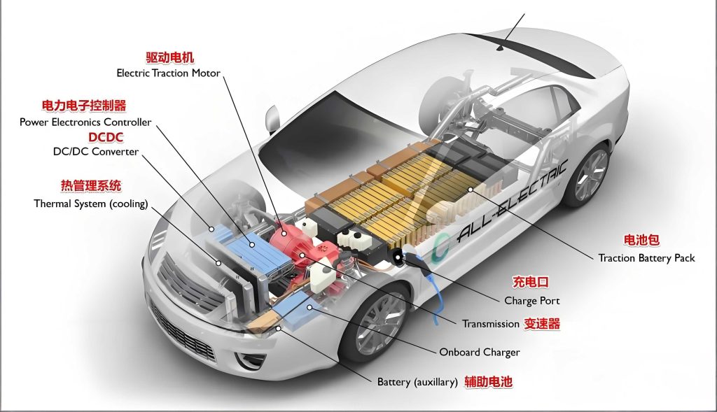
The core innovation lies in a dual-module architecture that segregates the refrigerant and coolant circuits. This approach moves beyond simple component compaction by fundamentally re-architecting the fluid pathways. The refrigerant module integrates key components such as expansion valves, solenoid valves, the liquid-cooled condenser (chiller), and the accumulator onto a single, manifold-like fluid plate. Similarly, the coolant module consolidates pumps, multi-way valves, sensors, and the coolant reservoir into a compact, 3D-printed nylon manifold. This design philosophy drastically reduces the number of external hoses and connection points compared to a conventional layout for a battery electric car. The physical integration offers the potential for reduced weight, lower leak risk, and simplified assembly. However, integrating multiple flow paths into a single module raises critical engineering concerns regarding internal flow resistance and unwanted heat transfer (thermal cross-talk) between adjacent high- and low-temperature circuits, which could undermine system efficiency.
To evaluate the hydraulic and thermal performance of the proposed modules, a comprehensive simulation study was conducted using Computational Fluid Dynamics (CFD). The simulations solved the fundamental governing equations for fluid flow and heat transfer to predict pressure drops and heat exchange between fluid channels under various operating conditions typical for a battery electric car. The governing equations for fluid flow include the continuity and momentum (Navier-Stokes) equations. For an incompressible flow, these can be expressed as:
$$
\nabla \cdot \mathbf{u} = 0
$$
$$
\rho \frac{\partial \mathbf{u}}{\partial t} + \rho (\mathbf{u} \cdot \nabla) \mathbf{u} = -\nabla p + \mu \nabla^2 \mathbf{u} + \rho \mathbf{g}
$$
where \( \mathbf{u} \) is the velocity vector, \( \rho \) is the fluid density, \( p \) is pressure, \( \mu \) is the dynamic viscosity, and \( \mathbf{g} \) is the gravitational acceleration vector. For turbulent flows, appropriate modeling such as the Reynolds-Averaged Navier-Stokes (RANS) equations with a k-ε or k-ω turbulence model is employed. The energy equation, governing heat transfer, is given by:
$$
\rho c_p \frac{\partial T}{\partial t} + \rho c_p (\mathbf{u} \cdot \nabla) T = k \nabla^2 T + \dot{q}
$$
where \( c_p \) is the specific heat capacity, \( T \) is temperature, \( k \) is thermal conductivity, and \( \dot{q} \) represents volumetric heat sources.
Boundary conditions for the simulations were defined based on extreme and typical operating scenarios for a battery electric car, as summarized in Table 1. The target flow resistances were derived from the performance characteristics of system pumps and historical data from non-integrated systems.
| Module | Mode | Circuit/Sub-mode | Flow Rate | Inlet Temp. (°C) | Pressure (Bar abs.) | Flow Resistance Target (kPa) |
|---|---|---|---|---|---|---|
| Refrigerant | Battery Cooling | High Load | 280 kg/h | 16.8 | 5.2 | ≤ 90 |
| Cabin Cooling | High Load | 200 kg/h | 6.5 | 3.7 | ≤ 60 | |
| Heat Pump Heating | Standard | 70 kg/h | -22 | 1.5 | ≤ 27 | |
| Coolant | Battery Cooling Mode | Motor Circuit | 16 L/min | 50 | – | ≤ 20 |
| Battery Cooling Mode | Battery Circuit | 25 L/min | 20 | – | ≤ 25 |
The simulation results for the refrigerant module are presented graphically below. The flow resistance remained within the target limits across all modes. The maximum pressure drop of 75 kPa was observed on the low-pressure side during the high-load battery cooling mode, which is well within the pump compressor’s capability. Crucially, the analysis of thermal cross-talk revealed that parasitic heat exchange between high- and low-temperature refrigerant channels was minimal. The maximum calculated heat transfer was 83.6 W from the hot side to the cold side during cabin cooling, which is negligible compared to the system’s total cooling capacity of several kilowatts in a battery electric car. This is attributed to strategic routing and separation of channels within the manifold plate.
The coolant module’s performance was similarly validated. The flow resistance for both the motor and battery cooling circuits under high-load conditions was simulated. The results, broken down by key sections of the manifold, are shown in Table 2. The total pressure drop for the motor circuit was 16.6 kPa, and for the battery circuit, it was 17.3 kPa. Both values are comfortably below the targets and align with the efficient operating point of the selected coolant pumps for a battery electric car. Thermal cross-talk in the coolant manifold, where motor and battery loops run in close proximity, was also assessed. The simulated heat exchange was 189.5 W during battery cooling mode. While non-zero, this value is very small relative to the total heat rejection load (on the order of 9 kW), confirming that the design effectively mitigates unwanted thermal coupling.
| Coolant Circuit | Manifold Segment | Simulated Flow Resistance (kPa) |
|---|---|---|
| Motor Loop | LTR Outlet to Pump Inlet | 5.7 |
| Valve Outlet to LTR Inlet | 4.0 | |
| Total (Simulated) | 16.6 | |
| Battery Loop | Chiller Outlet to Battery Plate | 8.5 |
| Battery Plate to Valve | 5.5 | |
| Total (Simulated) | 17.3 |
Following the simulation phase, physical prototypes of both the refrigerant and coolant modules were manufactured. The refrigerant module utilized an aluminum fluid plate with welded ports and mounting bosses, while the coolant manifold was produced via additive manufacturing from nylon. These modules, along with other key components like the compressor, outdoor heat exchanger, and cabin HVAC unit, were assembled into a complete thermal management system prototype for a battery electric car.
To rigorously evaluate the integrated system’s performance, a sophisticated test bench was constructed. This bench featured two environmentally controlled chambers (indoor and outdoor) to simulate ambient conditions, wind tunnels to provide controlled airflow across heat exchangers, and a comprehensive sensor suite. The system was tested under several steady-state conditions spanning severe and moderate climates, as defined in Table 3. Key performance metrics measured included cooling/heating capacity, compressor power consumption, and system Coefficient of Performance (COP). The COP is defined as:
$$
\text{COP}_{\text{cooling}} = \frac{Q_{\text{cooling}}}{W_{\text{comp}}} , \quad \text{COP}_{\text{heating}} = \frac{Q_{\text{heating}}}{W_{\text{comp}}}
$$
where \( Q \) is the useful thermal energy transfer and \( W_{\text{comp}} \) is the compressor electrical power input.
| Test Condition | Outdoor Temp. (°C) | Indoor Temp. (°C) | Front-end Air Speed (m/s) | Cabin Airflow (m³/h) | Relative Humidity (%) |
|---|---|---|---|---|---|
| 1. Severe Cooling | 43 | 40 | 4.0 | 480 | 40 |
| 2. Standard Cooling | 35 | 27 | 2.5 | 480 | 50 |
| 3. Thermal Balance Cooling | 35 | 27 | 2.5 | 200 | 50 |
| 4. Mild Heating | -7 | 0 | 2.5 | 200 | 35 |
| 5. Severe Heating | -10 | -10 | 2.5 | 320 | 35 |
The experimental results demonstrated the efficacy of the integrated modular design for a battery electric car. The measured flow resistance on the low-pressure side of the refrigerant circuit was consistently low, under 40 kPa for cooling modes and below 10 kPa for heating modes, validating the simulation predictions and confirming the hydraulic efficiency gained from reducing lengthy hoses. Most importantly, the system exhibited excellent energy efficiency across the board. As shown in the performance summary, the COP exceeded 2.5 in all test conditions. Notably, under the thermal balance cooling condition (Condition 3), the COP reached 3.5, indicating highly efficient operation. In heating mode, the COP values were above 3.0, even at an ambient temperature of -10°C, showcasing the system’s capability to provide cabin and battery warmth with minimal impact on the driving range of a battery electric car.
In conclusion, this work successfully designed, analyzed, and validated an integrated modular thermal management system tailored for battery electric cars. The dual-module architecture effectively addresses the packaging and efficiency challenges of conventional systems. Comprehensive CFD simulations confirmed that the integrated design maintains low flow resistance and minimal parasitic heat transfer. Experimental testing on a full-system prototype verified these findings and demonstrated superior energy efficiency, with COP values consistently above 2.5 and reaching up to 3.5 under balanced conditions. This integrated modular approach presents a promising solution for the next generation of thermal management systems in battery electric cars, contributing directly to improved vehicle range, performance, and packaging flexibility. Future work may focus on further material optimization, dynamic control strategy development for the integrated modules, and lifecycle analysis to quantify the total cost and environmental benefits for mass-produced battery electric cars.