
When a power battery electric vehicle refuses to enter its ready state, the root cause is frequently neither a depleted pack nor a failed traction motor but a break in a low-voltage signal loop that never carries propulsion current. That loop is the high-voltage interlock, a safety architecture now treated as mandatory equipment on modern power battery platforms. A systematic examination of the technology, covering standards requirements, control principles, diagnostic methods and production-vehicle application, has been consolidated into a four-dimensional framework intended to support technicians who inspect and repair new-energy vehicles.
The work addresses a typical failure mode in power battery electric vehicles: a vehicle that cannot be powered up because the high-voltage interlock circuit has been interrupted. Because the interlock is a low-voltage supervision mechanism wrapped around the high-voltage architecture, its failure produces symptoms that can easily be misattributed to the power battery itself, to the battery management system, or to the charging system. Understanding how the interlock is defined, how it is structured, how it is diagnosed and how it behaves on a specific production power battery vehicle therefore forms a complete service competency rather than a narrow troubleshooting trick.
The analysis is organised around four dimensions. The first establishes the regulatory boundary that separates high voltage from low voltage and the standards that compel manufacturers to fit interlock devices. The second explains the control logic that governs what a power battery management system or a vehicle control unit does when interlock integrity is lost, both at key-on and while the vehicle is in motion. The third sets out the diagnostic methods available in the workshop, distinguishing loop-continuity testing from waveform-based signal analysis. The fourth applies the framework to a production power battery electric vehicle fitted with two separate interlock loops, one dedicated to the direct-current high-voltage path and one dedicated to the alternating-current charging path.
- 1. Standards Framework: Defining the High-Voltage Boundary and the Interlock Mandate
The regulatory starting point is the boundary between low voltage and high voltage. Under the electric vehicle safety requirements standard GB 18384—2025, a direct-current voltage exceeding 60 V, or an alternating-current voltage exceeding 30 V in root-mean-square terms, is classified as Class B voltage, which is to say high voltage. This threshold is not an abstract definition. It determines which circuits must be protected, which connectors must be interlocked, and which diagnostic procedures require qualified personnel and insulated tooling.
The second regulatory pillar is the electrical safety specification for electrically propelled road vehicles, ISO 6469-3:2021. That document requires high-voltage connectors and protective enclosures that are readily removable, or removable by hand without tools, to be equipped with a high-voltage interlock device. The logic behind the requirement is straightforward: any connection that a person can separate without instrumentation is a connection that can be separated while the system is energised, and the interlock exists to make that separation safe by ensuring the power battery is disconnected and discharged before the hazardous conductor becomes exposed.
For designers of power battery systems, the standards framework has three practical consequences. First, every high-voltage connector on the power battery pack, on the power distribution unit, on the electric compressor, on the positive temperature coefficient heater and on the charging interface becomes a candidate for interlock supervision. Second, the interlock loop must be routed so that it is physically associated with the high-voltage conductors it supervises, so that a fault affecting the power path is likely to affect the signal path as well. Third, the response to an interlock break must be fast enough and complete enough to satisfy the discharge requirement, which in turn drives the control strategy implemented in the power battery management system.
- 2. Definition and Safety Role of High-Voltage Interlock in Power Battery Systems
High-voltage interlock is defined as the use of a low-voltage signal to confirm the integrity of the entire high-voltage electrical system, ensuring that every high-voltage component connector on the vehicle is fully seated and that no short circuit or open circuit exists in the supervised path. The interlock is therefore not a power-carrying circuit. It is a verification circuit, and its value lies entirely in what it proves about the circuits that do carry power.
The safety function becomes clear when the loop is broken during operation. If the high-voltage system circuit is disconnected, or if its integrity is compromised while the vehicle is running, the power battery management system or the vehicle control unit initiates a safety protection strategy. The purpose is to prevent the arc damage that occurs when high-voltage components are plugged or unplugged under load. An interlock that signals a separation before the power terminals actually part allows the control system to remove the load current first, which converts a potentially destructive and dangerous event into an orderly shutdown.
At vehicle start-up the behaviour is distinctive. When the power battery management system or the vehicle control unit detects that the high-voltage interlock loop is open, it triggers a fault alarm. The ready indicator on the instrument cluster does not illuminate, and the powertrain fault indicator is switched on. The control unit then commands the positive and negative contactors inside the power battery pack to open, with the result that the vehicle cannot be raised to high voltage and cannot be driven. This is the classic no-start complaint that brings a power battery electric vehicle into the workshop.
While the vehicle is being driven, the response is graded rather than absolute. If the power battery management system or the vehicle control unit detects an interlock loop fault, it illuminates the fault indicator as before, but it also commands the power battery pack to limit its power output. The output power of the drive motor is reduced, and the vehicle is held to a low speed. The driver is expected to stop the vehicle as soon as it is safe to do so and to arrange inspection and repair. The distinction matters for diagnosis: a vehicle that will not start at all points to a loop that was already open at key-on, whereas a vehicle that starts and then loses power points to a fault that developed after the initial integrity check.
- 3. Three Interlock Categories Shape Power Battery Safety Architecture
High-voltage interlock is implemented in three categories: structural interlock, functional interlock and software interlock. Each addresses a different failure pathway, and a complete power battery electric vehicle will normally use all three.
Structural interlock places an interlock circuit directly on the high-voltage connector. If any connector is accidentally separated while the system is energised, the power battery management system or the vehicle control unit detects the resulting open circuit in the interlock loop without delay. To protect personnel, the system immediately starts an alarm, disconnects the main high-voltage circuit electrically, and activates active discharge so that the high-voltage potential falls below 60 V within five seconds. Cover-open detection is a further application of the same structural principle, extending supervision from the connector to the enclosure.
Functional interlock applies a charging-priority rule. While the power battery electric vehicle is charging, or while a charging gun is connected, the vehicle is not permitted to be powered up for driving. Certain auxiliary functions remain available, notably the air-conditioning system, including compressor cooling and positive temperature coefficient heater warming. The control strategy exists to prevent the cable drag and personal safety hazards that would arise if a vehicle attempted to drive away with a charging cable attached.
Software interlock involves high-voltage components that participate through the communication network rather than through a hardwired loop. The principal participants are the positive temperature coefficient heater, the electric compressor and the power battery pack. Once the high-voltage system has been powered up normally, the heater or the compressor begins monitoring the voltage state on the high-voltage side. If an abnormality is detected, the air-conditioning system sends the high-voltage abnormality information over the controller area network to the power battery management system or the vehicle control unit, which triggers a high-voltage interlock fault alarm. On receipt of the alarm, the control unit immediately limits or interrupts the function of the heater or the compressor to keep the vehicle safe.
A newer trend is now emerging in power battery architectures. When high-voltage components begin to draw energy from the power battery pack, they independently check their connection state to the high-voltage positive and negative terminals and report the result as a message frame to the vehicle control unit or the power battery management system. This approach moves part of the integrity verification into the component itself and complements the hardwired loop, further improving vehicle safety and supporting stable operation of the high-voltage system.
| Interlock category | Supervision medium | Typical participants | Control response |
|---|---|---|---|
| Structural interlock | Hardwired interlock loop integrated into the high-voltage connector; cover-open detection | High-voltage connectors on the power battery pack, power distribution assembly, compressor, heater and charging interface | Alarm, disconnection of the main high-voltage circuit, active discharge to below 60 V within five seconds |
| Functional interlock | Charging-connection status and charging-priority logic | Charging interface and charging gun connection | Driving power-up inhibited during charging; air-conditioning and heater operation permitted |
| Software interlock | Controller area network messages and high-voltage side voltage monitoring | Positive temperature coefficient heater, electric compressor, power battery pack | High-voltage abnormality reported to the power battery management system or vehicle control unit; function limited or interrupted |
- 4. Physical Structure and Operating Principle of the Interlock Loop
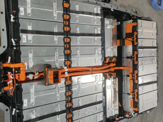
The high-voltage interlock device uses a low-voltage interlock conductor as its signal line. That conductor is routed in parallel with the high-voltage power cables inside the same high-voltage harness protective sleeve, and it is connected in series through every high-voltage component to build a complete loop. Because the signal conductor shares the route and the environmental exposure of the power conductors, mechanical damage, chafing, heat exposure or connector disturbance tends to affect both, which is precisely the design intent.
The connector design itself carries part of the safety logic. In an interlocked high-voltage connector, the high-voltage power terminals and the interlock terminal in the middle of the connector differ in physical length. During mating, the high-voltage terminals engage first and the interlock terminal engages afterwards. During separation, the low-voltage interlock terminal disengages first and the high-voltage terminals disengage afterwards. The sequence guarantees that the interlock signal is always the last connection made and the first connection broken, so the control system is informed of an impending separation before any power terminal is exposed.
The interlock signal is a voltage signal. Several forms are in use: a 12 V level signal, a 5 V level signal, a 12 V square wave signal and a 5 V square wave signal. The 12 V square wave form is currently the most widely applied. The interlock signal is emitted by the controller, travels along the interlock line, passes in sequence through the high-voltage connectors of each high-voltage module, and then returns to the controller. The controller compares the signal it transmitted with the signal it received and uses the comparison to judge the integrity of the supervised high-voltage line.
Because the comparison is between a transmitted pattern and a received pattern, the interlock is capable of detecting conditions that a simple continuity check would miss. A short circuit to a stable voltage, an intermittent connection that happens to close at the moment of measurement, or a signal degraded by corrosion can all produce a received waveform that differs from the transmitted waveform while a basic resistance measurement still appears acceptable. This is the technical reason why waveform-based diagnosis occupies a distinct and important place in the service procedure.
| Signal form | Characteristic | Diagnostic implication |
|---|---|---|
| 12 V level signal | Static voltage level carried on the interlock conductor | Continuity and short-to-ground or short-to-power conditions can be assessed with a multimeter |
| 5 V level signal | Static voltage level at a lower potential | Same measurement approach, with reference to the lower nominal value |
| 12 V square wave signal | Pulse-width modulated pattern emitted by the controller and returned through the loop | Oscilloscope comparison of transmitted and received waveforms reveals opens, shorts and signal degradation |
| 5 V square wave signal | Pulse-width modulated pattern at a lower potential | Oscilloscope comparison, with attention to the reduced amplitude |
- 5. Diagnostic Methodology for High-Voltage Interlock Faults
The common fault phenomena are consistent across power battery electric vehicle platforms. After start-up, the ready indicator fails to illuminate and the vehicle cannot be raised to high voltage. Alternatively, when a charging gun is connected, the charging connection indicator illuminates but charging does not take place. Both symptoms point to a supervision circuit that is not reporting the integrity the control system requires before it will close the power battery contactors.
Analysis of the possible causes, drawing on workshop experience, groups the failure modes into three families. The first is mechanical failure of the high-voltage interlock connector, including a loose, deformed or corroded interlock terminal. The second is electrical failure of the high-voltage interlock circuit, including an open circuit, a short circuit or a high-resistance connection in the interlock wiring. The third is a local controller fault, such as an internal mechanical or electronic failure within the power battery management system, the vehicle control unit or a comparable module.
Two detection methods are available, and they are complementary rather than alternative. The first is the interlock loop diagnostic method. It takes the closure and continuity of the interlock loop as the precondition for normal high-voltage interlock operation, and it narrows the fault range progressively by measuring resistance between the output terminal and the input terminal of the loop until the fault is located. The second is the interlock signal diagnostic method. It uses an oscilloscope to capture the interlock signal waveform and narrows the fault range by comparing the waveform at the output terminal with the waveform at the input terminal until the fault is located.
The practical value of running both methods lies in the different failure populations they address. Resistance measurement is fast, requires only a multimeter, and reliably identifies a clean open circuit or a dead short. Waveform comparison requires an oscilloscope and a known-good reference pattern, but it exposes intermittent connections, signal degradation and pattern distortion that a resistance reading cannot reveal. A workshop that relies on resistance measurement alone will occasionally replace a component that was never defective, because the loop appeared continuous at the moment of the test.
| Fault family | Specific examples | Indicative diagnostic approach |
|---|---|---|
| Connector mechanical fault | Interlock terminal loose, deformed or corroded | Visual inspection, terminal fit check, loop resistance measurement across the connector |
| Circuit electrical fault | Interlock wiring open circuit, short circuit or high-resistance connection | Loop resistance measurement, waveform comparison at output and input terminals |
| Controller local fault | Internal fault within the power battery management system, vehicle control unit or comparable module | Verification of signal emission and signal reception at the controller terminals |
- 6. Application Analysis in a Production Power Battery Electric Vehicle
A production power battery electric vehicle provides a concrete illustration of how the architecture is deployed. The vehicle in question carries two high-voltage interlock lines. One is the direct-current high-voltage interlock, whose supervised high-voltage components include the power battery management system, the power distribution assembly with its high-voltage connectors for the heater, the compressor and the power battery, and the high-voltage connector of the power battery pack itself.
The routing of the direct-current loop follows a defined path. The high-voltage interlock signal is emitted from terminal BK45(B)/4 of the battery management unit and passes through terminal BK51/30 into the power battery pack. It leaves the pack at terminal BK51/29 and travels to terminal BK46/12 of the power distribution assembly. Within that assembly it passes in sequence through the high-voltage component connectors for the heater, the air-conditioning compressor and the power battery, and finally exits at terminal BK46/13 to reach terminal BK45(B)/5, completing the high-voltage interlock loop.
The second line is the alternating-current high-voltage interlock. Its supervised high-voltage components are principally the battery management unit, the power distribution assembly, the alternating-current charging high-voltage connector and the low-voltage connector of the power distribution assembly. The high-voltage interlock signal is emitted from terminal BK45(B)/10, enters terminal BK46/15, passes through the alternating-current charging high-voltage connector, and exits at terminal BK46/14 to reach terminal BK45(B)/11. If this line is not functioning correctly, the power battery control unit will store a related diagnostic trouble code and the vehicle will be unable to raise its power battery to high voltage.
| Interlock line | Signal origin | Routed through | Signal return | Consequence of a fault |
|---|---|---|---|---|
| Direct-current high-voltage interlock | Battery management unit terminal BK45(B)/4 | Power battery pack via BK51/30 and BK51/29; power distribution assembly via BK46/12; heater, air-conditioning compressor and power battery high-voltage connectors | BK46/13 to BK45(B)/5 | High-voltage interlock fault stored; vehicle cannot be raised to high voltage |
| Alternating-current high-voltage interlock | Battery management unit terminal BK45(B)/10 | Power distribution assembly via BK46/15; alternating-current charging high-voltage connector | BK46/14 to BK45(B)/11 | Diagnostic trouble code stored by the power battery control unit; vehicle cannot be raised to high voltage |
Both the direct-current and the alternating-current high-voltage interlock signals on this power battery electric vehicle are modulated pulse-width signals emitted by the power battery management system, alternating between 0 V and 5 V. Diagnosis is carried out with an oscilloscope applied to the four terminals BK45(B)/4, BK45(B)/5, BK45(B)/10 and BK45(B)/11. When the circuit is intact, the feedback point receives a modulated pulse-width signal identical to the signal that was transmitted, and the power battery management system uses that returned pattern to perform continuity verification across the entire high-voltage interlock signal path.
The case demonstrates why terminal-level documentation is essential in power battery service. The two loops share a single controller, a single distribution assembly and a single diagnostic concept, yet they supervise different physical paths and produce different consequences when they fail. A technician who treats the interlock as a single undifferentiated circuit will waste diagnostic time; a technician who knows the origin terminal, the routing and the return terminal for each loop can move directly to the segment most likely to be at fault.
- 7. Service Implications and Industry Outlook
The consolidated framework carries several implications for the power battery service sector. The first concerns diagnostic equipment. Because the most widely deployed interlock signal form is a 12 V square wave, and because the production power battery vehicle examined here uses a 0 V to 5 V modulated pulse-width signal, a workshop that intends to diagnose interlock faults to component level must have an oscilloscope available alongside conventional multimeters. Resistance measurement remains valuable, but it is not sufficient on its own.
The second implication concerns technician knowledge. The interlock loop is a low-voltage circuit that supervises a high-voltage system, and the two must be understood together. A technician who understands only the low-voltage side will struggle to explain why an interlock break prevents the power battery contactors from closing; a technician who understands only the high-voltage side will not think to check a five-volt signal when the vehicle refuses to start. The four dimensions examined in the analysis, namely standards requirements, control principles, diagnostic methods and application analysis, are intended precisely to build that combined understanding.
The third implication concerns the evolution of the architecture itself. The movement toward high-voltage components that independently verify their connection to the high-voltage positive and negative terminals, and that report the result over the controller area network to the vehicle control unit or the power battery management system, changes the diagnostic landscape. Hardwired loop continuity will remain necessary but will no longer be sufficient as a description of interlock integrity. Technicians will increasingly need to read component-level connection status messages as well as measure loop resistance and capture waveforms.
The fourth implication concerns safety practice. The interlock exists to prevent live plugging and unplugging of high-voltage connectors, and its five-second active discharge requirement defines the interval within which the high-voltage potential must fall below 60 V. Service procedures that bypass an interlock, that defeat a cover-open detection switch, or that assume a vehicle is de-energised because the ready indicator is dark all undermine the protection the architecture was designed to provide. The correct practice is to verify de-energisation with measurement, to respect the discharge interval, and to restore every interlock connection to its designed condition before returning the power battery electric vehicle to service.
Taken together, the standards requirements, the definition and safety role of the interlock, the three interlock categories, the physical structure and operating principle of the loop, the two diagnostic methods and the production-vehicle application form a coherent reference for technicians who troubleshoot and repair high-voltage interlock faults on power battery electric vehicles. The framework addresses the typical complaint of a vehicle that cannot be powered up, and it does so by connecting the regulatory boundary that defines high voltage, the control logic that governs the power battery management system response, the measurement techniques available in the workshop, and the terminal-level routing found on an actual power battery platform.