
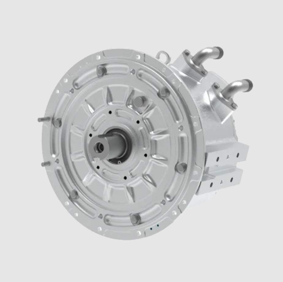
I designed and analyzed a flat-wire PMSM electric motor for new energy electric vehicles. My motivation is straightforward: the PMSM electric motor offers high power density, high torque density, compact size, low weight, and high efficiency, and these qualities make it a leading candidate for electric vehicle traction. I used flat-wire winding in the stator because flat conductors can be packed more tightly inside the slot than round wires. This increases the slot fill factor, reduces the end-winding length, lowers copper loss, and improves heat dissipation. The PMSM electric motor in my study therefore combines a flat-wire stator with a V-one double-layer permanent magnet rotor. The rotor topology provides saliency, and the resulting reluctance torque supports both overload capability and flux-weakening speed expansion.
I based my work on an 8-pole, 48-slot PMSM electric motor. The rated power is 16 kW, the peak power is 35 kW, the rated torque is 29 N·m, the peak torque is 110 N·m, the rated speed is 5400 r/min, and the maximum speed is 9000 r/min. The stator outer diameter is 153 mm, the core length is 86 mm, the selected stator inner diameter is 109 mm, the selected air-gap length is 0.7 mm, and the winding uses four layers. I selected a V-one permanent magnet arrangement to improve flux weakening and to extend the constant-power speed range. The flat wire specification is 3.35 mm by 2.5 mm, and with 0.25 mm insulation the pure copper slot fill factor reaches 74.8%. This value is important because a high slot fill factor allows the PMSM electric motor to produce more torque within the same frame.
The core electromagnetic torque of a PMSM electric motor can be written as
$$T = \frac{3}{2} p \left[ \lambda_{pm} i_q + \left( L_d – L_q \right) i_d i_q \right]$$
where \(p\) is the pole pair number, \(\lambda_{pm}\) is the permanent magnet flux linkage, \(i_d\) and \(i_q\) are the d-axis and q-axis currents, and \(L_d\) and \(L_q\) are the d-axis and q-axis inductances. The first term is the permanent magnet torque, and the second term is the reluctance torque. In my PMSM electric motor, the V-one rotor increases the saliency ratio, so the second term contributes significantly to the total torque. I also evaluated torque ripple using
$$T_{ripple} = \frac{T_{max} – T_{min}}{T_{avg}} \times 100\%$$
where \(T_{max}\), \(T_{min}\), and \(T_{avg}\) are the maximum, minimum, and average torque values over one steady-state period. The cogging torque, which is an important source of vibration and acoustic noise in a PMSM electric motor, can be expressed as
$$T_{cog} = -\frac{1}{2} \frac{dW}{\partial \theta}$$
where \(W\) is the magnetic co-energy and \(\theta\) is the rotor position. The efficiency of the PMSM electric motor is calculated from
$$\eta = \frac{P_{out}}{P_{in}} \times 100\%$$
and the total harmonic distortion of the back electromotive force is evaluated by
$$THD = \frac{\sqrt{E_2^2 + E_3^2 + E_4^2 + \cdots + E_{13}^2}}{E_1} \times 100\%$$
where \(E_1\) is the fundamental amplitude and \(E_2\) through \(E_{13}\) are the harmonic amplitudes. These equations guided my design choices for the flat-wire PMSM electric motor.
| Parameter | Value | Parameter | Value |
|---|---|---|---|
| Rated power | 16 kW | Stator inner diameter | 109 mm |
| Peak power | 35 kW | Core length | 86 mm |
| Rated torque | 29 N·m | Air-gap length | 0.7 mm |
| Peak torque | 110 N·m | Stator slots | 48 |
| Rated speed | 5400 r/min | Pole number | 8 |
| Maximum speed | 9000 r/min | Magnet type | V-one |
| Stator outer diameter | 153 mm | Winding layers | 4 |
I first investigated the stator side of the PMSM electric motor because the stator inner diameter, air-gap length, and slot geometry affect the air-gap flux density, the magnetic loading, the electric loading, the torque output, and the torque ripple. When the stator outer diameter is fixed, the stator inner diameter controls the split between yoke thickness and slot area. A smaller inner diameter leaves more room for the yoke but reduces the stator bore area. A larger inner diameter increases the bore area but compresses the yoke. Both effects change the magnetic saturation level and the torque waveform. I scanned the stator inner diameter from 105 mm to 115 mm. The average torque first increased and then decreased, while the torque ripple first decreased and then increased. The minimum torque ripple occurred at an inner diameter of 109 mm, and the maximum torque still satisfied the design requirement. Therefore, I selected 109 mm as the stator inner diameter of the PMSM electric motor.
| Stator inner diameter (mm) | Average torque trend | Torque ripple trend | Decision |
|---|---|---|---|
| 105 | Moderate | High | Not selected |
| 107 | Increasing | Decreasing | Candidate |
| 109 | High and acceptable | Minimum | Selected |
| 111 | Decreasing | Increasing | Not selected |
| 113 | Lower | Higher | Not selected |
| 115 | Lowest | Highest | Not selected |
I then studied the air-gap length of the PMSM electric motor. The air-gap length affects the magnetizing inductance, the power factor, the flux-weakening capability, and the mechanical robustness of the rotor assembly. A smaller air gap increases the air-gap flux density and improves the power factor, but it may reduce mechanical clearance and increase the risk of manufacturing difficulties. A larger air gap reduces the d-axis inductance and can lower the maximum speed under voltage limit. I scanned the air-gap length from 0.5 mm to 1.0 mm. The average torque decreased as the air gap increased. The torque ripple first decreased and then increased. The minimum torque ripple occurred at 0.7 mm. Since the torque requirement was still satisfied at this value, I selected an air-gap length of 0.7 mm for my PMSM electric motor.
| Air-gap length (mm) | Average torque trend | Torque ripple trend | Decision |
|---|---|---|---|
| 0.5 | Highest | Moderate | Not selected |
| 0.6 | High | Decreasing | Candidate |
| 0.7 | Acceptable | Minimum | Selected |
| 0.8 | Lower | Increasing | Not selected |
| 0.9 | Lower | Higher | Not selected |
| 1.0 | Lowest | High | Not selected |
For the flat-wire PMSM electric motor, I used a rectangular stator slot because rectangular slots match the geometry of flat conductors. I defined the slot height as \(h_1\), the slot width as \(w_1\), the slot opening height as \(h_2\), and the slot opening width as \(w_2\). The flat wire dimensions and the slot dimensions must be co-designed. If the slot is too deep, the slot leakage inductance increases and the torque may decrease. If the slot is too wide, the tooth width is reduced and the tooth flux density may become too high. I scanned \(h_1\) from 12.0 mm to 14.0 mm and \(w_1\) from 3.5 mm to 4.5 mm. The average torque decreased as \(h_1\) increased. The torque ripple first decreased slowly and then increased. For \(w_1\), both the average torque and the torque ripple decreased as the width increased. Considering the torque requirement and the torque ripple, I selected \(h_1 = 12.5\) mm and \(w_1 = 4.15\) mm. I also scanned the slot opening height \(h_2\) and the slot opening width \(w_2\). The average torque decreased as \(h_2\) increased, while the torque ripple first decreased and then increased. The average torque increased as \(w_2\) increased, while the torque ripple first decreased and then increased. I selected \(h_2 = 1.0\) mm and \(w_2 = 1.5\) mm because this combination gave low torque ripple and acceptable torque.
| Dimension | Symbol | Selected value |
|---|---|---|
| Slot height | \(h_1\) | 12.5 mm |
| Slot width | \(w_1\) | 4.15 mm |
| Slot opening height | \(h_2\) | 1.0 mm |
| Slot opening width | \(w_2\) | 1.5 mm |
| Flat wire size | \(w \times h\) | 3.35 mm × 2.5 mm |
| Insulation thickness | \(t_{ins}\) | 0.25 mm |
| Copper slot fill factor | \(k_{cu}\) | 74.8% |
The copper slot fill factor can be estimated by
$$k_{cu} = \frac{A_{cu}}{A_{slot}} \times 100\%$$
where \(A_{cu}\) is the total copper area and \(A_{slot}\) is the slot area. In my PMSM electric motor, the flat-wire arrangement increased \(k_{cu}\) to 74.8%, which is significantly higher than what is typically achieved with round wire. This high fill factor reduces the DC resistance, lowers the copper loss at a given current, and improves the thermal path from the conductor to the stator core. For an electric vehicle traction PMSM electric motor, these benefits are directly translated into higher continuous torque and better efficiency.
After the stator design, I optimized the rotor surface of the PMSM electric motor by introducing auxiliary slots. The purpose of these auxiliary slots is to shape the air-gap permeance, reduce the harmonic content of the air-gap flux density, suppress the cogging torque, and reduce the torque ripple. I used two asymmetric auxiliary slots per permanent magnet pole. The key variables were the auxiliary slot depth \(h_{fc}\), the slot position angle \(\theta_r\), the inner-half slot angle \(\theta_{in}\), and the outer-half slot angle \(\theta_{out}\). I first performed single-variable sweeps to determine the useful ranges. The results showed that the auxiliary slot geometry has a strong influence on torque ripple and a moderate influence on average torque. As \(h_{fc}\) increased, both average torque and torque ripple first decreased and then increased. As \(\theta_r\) increased, average torque first decreased slowly and then increased, while torque ripple first decreased and then increased. As \(\theta_{in}\) increased, average torque decreased, while torque ripple first decreased and then increased. As \(\theta_{out}\) increased, average torque increased, while torque ripple first decreased and then increased. Therefore, a carefully chosen auxiliary slot can greatly reduce torque ripple without sacrificing much average torque.
| Level | \(h_{fc}\) (mm) | \(\theta_r\) (deg) | \(\theta_{in}\) (deg) | \(\theta_{out}\) (deg) |
|---|---|---|---|---|
| -1 | 0.2 | 125 | 17 | 17 |
| 0 | 0.4 | 127 | 20 | 20 |
| 1 | 0.6 | 129 | 23 | 23 |
I used a Box-Behnken response surface design to build surrogate models for the average torque \(T_{avg}\) and the torque ripple \(T_{ripple}\). The four factors were \(h_{fc}\), \(\theta_r\), \(\theta_{in}\), and \(\theta_{out}\). I then evaluated the candidate designs with finite element analysis. The response surface equations I obtained are
$$T_{avg} = 65.42 – 15.485 h_{fc} – 0.4504 \theta_r + 0.011 \theta_{in} + 0.1108 \theta_{out} + 0.8437 h_{fc}^2 + 0.001875 \theta_r^2 + 0.000972 \theta_{in}^2 + 0.11875 h_{fc} \theta_r – 0.03333 h_{fc} \theta_{in} + 0.01667 h_{fc} \theta_{out} – 0.000417 \theta_r \theta_{in} – 0.000833 \theta_r \theta_{out}$$
and
$$T_{ripple} = 425 + 100.9 h_{fc} – 8.10 \theta_r + 10.3 \theta_{in} – 3.69 \theta_{out} + 26.26 h_{fc}^2 + 0.0383 \theta_r^2 + 0.015 \theta_{in}^2 – 1.006 h_{fc} \theta_r + 0.368 h_{fc} \theta_{in} – 0.14 h_{fc} \theta_{out} – 0.087 \theta_r \theta_{in} + 0.0307 \theta_r \theta_{out} – 0.0064 \theta_{in} \theta_{out}$$
These equations are valid within the factor ranges listed in the table above. The fit quality was verified by the coefficient of determination \(R^2\), the adjusted coefficient of determination \(R^2_{adj}\), and the \(P\)-value. The response surface model for \(T_{avg}\) achieved \(R^2 = 99.95\%\) and \(R^2_{adj} = 99.88\%\). The response surface model for \(T_{ripple}\) achieved \(R^2 = 96.41\%\) and \(R^2_{adj} = 91.75\%\). In both cases the \(P\)-value was below 0.0001, which indicates that the surrogate models are accurate enough for multi-objective optimization of the PMSM electric motor.
| Metric | \(T_{avg}\) | \(T_{ripple}\) |
|---|---|---|
| \(P\)-value | < 0.0001 | < 0.0001 |
| \(R^2\) | 99.95% | 96.41% |
| \(R^2_{adj}\) | 99.88% | 91.75% |
| Run | \(h_{fc}\) | \(\theta_r\) | \(\theta_{in}\) | \(\theta_{out}\) | \(T_{avg}\) (N·m) | \(T_{ripple}\) (%) |
|---|---|---|---|---|---|---|
| 1 | 0 | -1 | 0 | -1 | 37.82 | 2.252 |
| 2 | 0 | 1 | 0 | -1 | 38.02 | 2.494 |
| 3 | 0 | 0 | -1 | 1 | 38.04 | 2.952 |
| 4 | 1 | 1 | 0 | 0 | 38.12 | 2.850 |
| 5 | -1 | 0 | -1 | 0 | 38.03 | 4.184 |
| 6 | 0 | 1 | 0 | 1 | 38.08 | 3.016 |
| 7 | 0 | 0 | 1 | 1 | 37.94 | 1.897 |
| 8 | 0 | 1 | 1 | 0 | 38.01 | 1.830 |
| 9 | 0 | 0 | 1 | -1 | 37.87 | 1.879 |
| 10 | 1 | -1 | 0 | 0 | 37.83 | 3.567 |
| 11 | 1 | 0 | 1 | 0 | 37.91 | 3.221 |
| 12 | 1 | 0 | 0 | 1 | 38.01 | 2.738 |
| 13 | -1 | 0 | 0 | 1 | 38.02 | 3.710 |
| 14 | 0 | -1 | 0 | 1 | 37.90 | 2.038 |
| 15 | -1 | 0 | 0 | -1 | 37.97 | 3.539 |
| 16 | 1 | 0 | -1 | 0 | 38.05 | 3.335 |
| 17 | 0 | 0 | -1 | -1 | 37.97 | 2.703 |
| 18 | 0 | 1 | -1 | 0 | 38.11 | 3.581 |
| 19 | 1 | 0 | 0 | -1 | 37.92 | 2.904 |
| 20 | -1 | -1 | 0 | 0 | 37.95 | 3.198 |
| 21 | 0 | -1 | -1 | 0 | 37.91 | 2.047 |
| 22 | -1 | 0 | 1 | 0 | 37.97 | 3.188 |
| 23 | 0 | -1 | 1 | 0 | 37.82 | 2.383 |
| 24 | -1 | 1 | 0 | 0 | 38.05 | 4.091 |
| 25 | 0 | -1 | 0 | -1 | 37.82 | 2.252 |
I combined the response surface models with the NSGA-II algorithm to solve the multi-objective optimization problem. The objective was to maximize average torque and minimize torque ripple. Because both objectives should be minimized in the algorithm, I defined the fitness functions as
$$f_1(X_i) = \frac{1}{T_{avg}(X_i)}$$
and
$$f_2(X_i) = T_{ripple}(X_i)$$
where \(X_i\) is the vector of auxiliary slot variables. The variable ranges were those listed in the factor-level table. The NSGA-II algorithm produced a Pareto set of candidate designs. I validated representative points with finite element analysis. The predicted and finite element results were close, and the remaining difference came mainly from the geometric rounding and mesh discretization. From the Pareto set I selected three representative schemes. The first scheme used \(h_{fc} = 0.48\) mm, \(\theta_r = 129^\circ\), \(\theta_{in} = 23^\circ\), and \(\theta_{out} = 20.91^\circ\). The second scheme used \(h_{fc} = 0.485\) mm, \(\theta_r = 129^\circ\), \(\theta_{in} = 23^\circ\), and \(\theta_{out} = 23^\circ\). The third scheme used \(h_{fc} = 0.434\) mm, \(\theta_r = 129^\circ\), \(\theta_{in} = 22.98^\circ\), and \(\theta_{out} = 17^\circ\). I compared the three schemes with the baseline PMSM electric motor without auxiliary slots.
| Variable | Scheme 1 | Scheme 2 | Scheme 3 |
|---|---|---|---|
| \(h_{fc}\) (mm) | 0.48 | 0.485 | 0.434 |
| \(\theta_r\) (deg) | 129 | 129 | 129 |
| \(\theta_{in}\) (deg) | 23 | 23 | 22.98 |
| \(\theta_{out}\) (deg) | 20.91 | 23 | 17 |
| Objective | No auxiliary slot | Scheme 1 | Scheme 2 | Scheme 3 |
|---|---|---|---|---|
| \(T_{avg}\) (N·m) | 38.1 | 38.03 | 38.03 | 37.98 |
| \(T_{ripple}\) (%) | 5.57 | 1.712 | 1.747 | 1.524 |
Scheme 3 gave the best torque ripple suppression. Compared with the baseline PMSM electric motor without auxiliary slots, the average torque decreased from 38.1 N·m to 37.98 N·m, a reduction of only 0.33%, while the torque ripple decreased from 5.57% to 1.524%, a reduction of 72.64%. Therefore, I selected scheme 3 as the final rotor auxiliary slot design for my PMSM electric motor. This result confirms that a multi-objective optimization workflow combining response surface models and NSGA-II can effectively balance average torque and torque ripple in a flat-wire PMSM electric motor.
I also analyzed the no-load performance of the optimized PMSM electric motor. The cogging torque is a key indicator at low speed. Before the auxiliary slots were introduced, the peak-to-peak cogging torque was 914.788 mN·m. After the auxiliary slots were introduced, the peak-to-peak cogging torque decreased to 429.2028 mN·m, which is a reduction of 53.08%. The optimized cogging torque peak value is about 0.22 N·m, which satisfies the design requirement of no more than 0.5 N·m. This reduction is important because low cogging torque improves low-speed smoothness, reduces vibration, and improves the control accuracy of the PMSM electric motor.
| Condition | Peak-to-peak cogging torque (mN·m) | Peak value (N·m) | Reduction |
|---|---|---|---|
| Without auxiliary slots | 914.788 | 0.457 | Baseline |
| With auxiliary slots | 429.2028 | 0.22 | 53.08% |
The no-load air-gap flux density also improved. After the asymmetric auxiliary slots were added, the fundamental amplitude of the no-load air-gap flux density increased slightly. The waveform became closer to a sinusoidal shape. The small depressions on both sides of the air-gap flux density waveform are caused by the auxiliary slot geometry, and they help reduce the distortion of the air-gap magnetic field. A more sinusoidal air-gap flux density is desirable because it reduces the harmonic content of the back electromotive force and lowers the torque ripple in the PMSM electric motor.
I analyzed the no-load back electromotive force at the maximum speed of 9000 r/min. The three line-to-line back electromotive force waveforms are sinusoidal and well balanced. I performed a Fourier decomposition of the phase back electromotive force. The total harmonic distortion calculated from the fundamental and the second through thirteenth harmonics is 3.04%. This low THD indicates that the optimized PMSM electric motor has a high-quality air-gap magnetic field and is suitable for field-oriented control.
| Quantity | Value |
|---|---|
| Maximum speed | 9000 r/min |
| Back EMF waveform | Three-phase sinusoidal |
| THD | 3.04% |
| Harmonics considered | 2nd to 13th |
I evaluated the magnetic field distribution at the maximum speed. The maximum flux density in the stator yoke is about 1.3 T, and the maximum flux density in the stator teeth is about 1.6 T. The magnetic bridge reaches about 2.3 T, which provides effective magnetic isolation. No severe saturation occurs in the main magnetic circuit, and the flux density distribution is reasonable for a traction PMSM electric motor. This distribution supports both torque production and flux weakening.
| Region | Maximum flux density (T) | Comment |
|---|---|---|
| Stator yoke | 1.3 | No severe saturation |
| Stator teeth | 1.6 | Acceptable for traction duty |
| Magnetic bridge | 2.3 | Effective magnetic isolation |
I then analyzed the load performance of the PMSM electric motor under four representative electric vehicle operating conditions: hill climbing, peak power, rated high-efficiency operation, and high-speed operation. At the hill-climbing point, the speed is 1000 r/min, the average torque is 113.86 N·m, and the torque ripple is 2.46%. At the peak-power point, the speed is 3800 r/min, the average torque is 113.84 N·m, and the torque ripple is 2.0%. At the rated high-efficiency point, the speed is 5400 r/min, the average torque is 37.98 N·m, and the torque ripple is 1.524%. At the high-speed point, the speed is 9000 r/min, the average torque is 53.66 N·m, and the torque ripple is 0.97%. These results show that the flat-wire PMSM electric motor can satisfy both the peak torque requirement and the high-speed torque requirement while maintaining low torque ripple.
| Operating condition | Speed (r/min) | Average torque (N·m) | Torque ripple (%) |
|---|---|---|---|
| Hill climbing | 1000 | 113.86 | 2.46 |
| Peak power | 3800 | 113.84 | 2.00 |
| Rated high efficiency | 5400 | 37.98 | 1.524 |
| High speed | 9000 | 53.66 | 0.97 |
I calculated the torque-speed external characteristics of the PMSM electric motor for both peak power and rated power. The peak-power external characteristic shows that the motor can produce high torque at low speed and then enter the constant-power region as speed increases. The rated-power external characteristic shows a similar shape but at a lower power level. The transition from constant torque to constant power is smooth. This behavior is essential for an electric vehicle traction PMSM electric motor because the vehicle needs high torque for starting and hill climbing, and it needs high speed for highway driving.
| Quantity | Requirement | Calculated result |
|---|---|---|
| Maximum speed power | At least 30 kW | 46.6 kW |
| Rated torque ripple | No more than 2% | 1.524% |
| Cogging torque | No more than 0.5 N·m | 0.22 N·m |
| Maximum efficiency | Greater than 95.5% | 96.63% |
| High-efficiency area | At least 85% | 91.36% |
The efficiency map is one of the most important performance summaries for a traction PMSM electric motor. I calculated the efficiency over the entire speed and torque range. The maximum efficiency reaches 96.63%, and the high-efficiency operating region, defined as efficiency greater than 85%, accounts for 91.36% of the operating map. The highest efficiency occurs near the rated operating condition. The PMSM electric motor maintains high efficiency over a wide speed range, which is beneficial for electric vehicle range and energy consumption. The wide high-efficiency area also reduces the demand on the cooling system because less loss is generated over typical driving cycles.
| Metric | Value |
|---|---|
| Maximum efficiency | 96.63% |
| High-efficiency threshold | 85% |
| High-efficiency area | 91.36% |
| Speed range | 1000 r/min to 9000 r/min |
| Torque range | Up to 113.86 N·m |
From my design and analysis, several conclusions can be drawn about the flat-wire PMSM electric motor. First, flat-wire winding raises the pure copper slot fill factor to 74.8%, which increases torque density and reduces copper loss. Second, the stator inner diameter, air-gap length, and slot geometry have a strong effect on torque and torque ripple. My selected values are 109 mm for the stator inner diameter, 0.7 mm for the air-gap length, 12.5 mm for the slot height, 4.15 mm for the slot width, 1.0 mm for the slot opening height, and 1.5 mm for the slot opening width. Third, asymmetric rotor auxiliary slots significantly reduce torque ripple and cogging torque. The optimized scheme reduces torque ripple by 72.64% and cogging torque by 53.08%, while the average torque decreases by only 0.33%. Fourth, the no-load back electromotive force has a THD of 3.04%, and the magnetic field distribution is reasonable, with a maximum yoke flux density of about 1.3 T, a maximum tooth flux density of about 1.6 T, and a magnetic bridge flux density of about 2.3 T. Fifth, the PMSM electric motor meets the traction requirements at hill climbing, peak power, rated operation, and high speed. The maximum efficiency is 96.63%, and the high-efficiency area is 91.36%.
I believe the design approach presented here is useful for the development of a high-performance PMSM electric motor for electric vehicles. The combination of flat-wire winding, V-one permanent magnet rotor topology, stator parameter optimization, and response-surface-based NSGA-II auxiliary slot optimization provides a practical path to high torque density, low torque ripple, low cogging torque, and wide high-efficiency operation. The PMSM electric motor I studied satisfies the target indicators and offers a strong reference for further design and characteristic analysis of flat-wire traction machines.