
Electric vehicle charging in residential areas is no longer a peripheral convenience; it is becoming a core electrical design requirement. I approach this subject from the perspective of a distribution designer who must reconcile three competing objectives: sufficient charging capacity for current and future users, safe and orderly integration with the existing residential power system, and economical operation of transformers and feeders. The rapid growth of electric vehicle charging demand means that a simple “install more chargers” strategy is inadequate. Every additional alternating-current or direct-current charger changes the load profile of the residential garage, affects voltage regulation, and influences transformer loading. My analysis therefore treats electric vehicle charging as a system-level design problem rather than a standalone equipment selection exercise.
In my assessment, the most important technical question is not whether a residential area can accept electric vehicle charging, but how much electric vehicle charging it can accept without compromising reliability, safety, and economic performance. This question requires a structured evaluation of layout, distribution topology, demand diversity, transformer reserve, and operational control. I use tables and formulas throughout this article to make the logic transparent and repeatable. The discussion covers feasibility, physical layout, distribution design, capacity calculation, demand-factor selection, transformer economic operation, and alternating-current charging optimization. Each section links back to the central goal of designing residential electric vehicle charging infrastructure that is safe, expandable, and economically justified.
Feasibility Assessment for Residential Electric Vehicle Charging
I begin with feasibility because electric vehicle charging projects often fail at the boundary between user demand and electrical capacity. A residential community may have sufficient parking spaces but insufficient transformer reserve; it may have adequate power but poor cable routing; or it may have both power and space but weak fire-safety separation. My feasibility framework therefore examines capacity, space, equipment selection, safety, user behavior, and operation and maintenance together. I do not treat any single criterion as decisive. Instead, I assign each criterion a design consequence and use the result to decide whether electric vehicle charging should be connected to the existing system, supplied by a dedicated transformer, or implemented in stages.
Capacity reserve is the first filter. I compare the existing transformer loading profile with the expected electric vehicle charging load. If the existing transformer has a stable spare capacity and the charging demand is small, a connection to the existing low-voltage network can be technically acceptable. If the charging demand is large, intermittent, and concentrated in the evening, I prefer a dedicated transformer or a dedicated charging distribution board with separate metering. Space is the second filter. I verify parking geometry, clearances, cable paths, ventilation, and fire access. Equipment selection is the third filter. I match alternating-current charging for long-dwell parking and direct-current charging for short-dwell or emergency replenishment. Safety and operation are continuous filters that apply to every stage.
| Dimension | Key question | Design consequence |
|---|---|---|
| Transformer reserve | Is there stable spare capacity after existing residential load? | Decides existing-network connection versus dedicated transformer |
| Parking geometry | Can chargers, cables, and clearances be accommodated? | Decides wall-mounted, floor-mounted, or bracket layout |
| Charging behavior | Do users park overnight or require fast replenishment? | Decides AC-dominant or DC-assisted configuration |
| Fire and ventilation | Are separation, detection, and smoke control adequate? | Decides zoning, compartmentation, and equipment enclosure |
| Metering and billing | Can electric vehicle charging be measured separately? | Decides sub-metering and management platform |
| Expandability | Can future chargers be added without major civil works? | Decides reserved conduits, spare breakers, and transformer space |
I also consider user behavior because electric vehicle charging load is not equal to the sum of nameplate ratings. A residential user typically arrives in the evening, parks for many hours, and does not need immediate full-power charging. This long-dwell pattern is favorable for alternating-current electric vehicle charging and for load shifting. However, the same pattern can produce a sharp evening peak if all users start charging at the same time. My feasibility assessment therefore distinguishes between connected load, demand load, and energy demand. Connected load is the sum of charger ratings. Demand load is the coincident power after diversity. Energy demand is the daily electricity required by the vehicles. A project that passes the energy test may still fail the demand test, and a project that passes the demand test may still fail the transformer loading test under worst-case conditions.
Layout and Physical Design of Electric Vehicle Charging Facilities
Physical layout is where electric vehicle charging design becomes practical. I place charging facilities in accessible public parking areas or designated garage zones, but I avoid locations that conflict with traffic flow, fire access, or pedestrian routes. I prefer locations near electrical rooms and vertical cable shafts because shorter cable routes reduce voltage drop and installation cost. At the same time, I maintain safe separation from fire-control rooms, transformer rooms, and other critical spaces. For electric vehicle charging in underground garages, I check headroom, cable tray routes, drainage, and ventilation. I also check whether the charger enclosure can be protected from vehicle impact and whether the charging cable can be managed without creating a trip hazard.
I use different installation methods according to parking geometry. For wall-adjacent spaces, I mount the charger on the wall or on a dedicated post near the rear of the vehicle, and I provide a wheel stop to prevent over-travel. For floor-mounted spaces, I use a pedestal or a movable bracket with a cable groove. For bracket-type spaces, I provide an activity bracket or cable channel at the front of the space. For underground pits or special zones, I pre-install a foundation and a power interface. I do not allow electric vehicle charging equipment to share a final circuit with unrelated charging equipment unless the circuit is specifically designed and interlocked for that purpose. This rule simplifies protection coordination and reduces the risk of nuisance tripping.
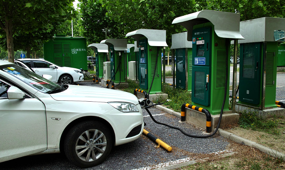
Fire safety and evacuation are non-negotiable in my layout decisions. I keep charging areas away from hazardous locations and ensure that each charging zone has a clear evacuation path. Where charging facilities are distributed across multiple garage zones, I coordinate fire compartmentation and smoke control with the architectural design. I also consider environmental effects: irrigation, vegetation, and rainwater can damage outdoor chargers, while dust and vehicle exhaust can affect indoor equipment. For high-power direct-current electric vehicle charging, I cluster the equipment near the transformer room to reduce cable length and voltage drop. For alternating-current electric vehicle charging, I distribute the equipment closer to parking spaces because the power level is lower and the dwell time is longer.
| Item | Design requirement | Reason |
|---|---|---|
| Charger location | Accessible parking area with clear identification | Improves usability and management |
| Traffic separation | Avoid main traffic lanes and blind corners | Reduces collision risk |
| Cable route | Short route to electrical shaft or distribution board | Reduces voltage drop and cost |
| Protection | Wheel stop, impact barrier, or pedestal protection | Protects equipment from vehicle impact |
| Fire access | Clear evacuation path and fire separation | Maintains life safety |
| Ventilation | Adequate air movement in enclosed garages | Limits heat and pollutant accumulation |
| Signage | Clear operating instructions and emergency contact | Improves safe use |
I also design the layout for maintenance. A charger that cannot be reached safely will not be maintained properly. I leave working space in front of distribution boards, and I avoid installing chargers in narrow corners where a technician cannot open the enclosure. I label each electric vehicle charging circuit at both ends, and I record the circuit-to-parking-space mapping in the as-built documentation. This mapping is essential for fault isolation and for future capacity expansion. When I plan a new garage, I reserve additional conduit capacity and wall space even if only a fraction of the parking spaces will receive chargers in the first phase. The marginal cost of reserved conduit is small compared with the cost of reopening finished walls and ceilings later.
Distribution System Design for Electric Vehicle Charging
Distribution design determines whether electric vehicle charging is a stable load or a source of nuisance. I use a differentiated approach. For a small number of chargers, I connect the electric vehicle charging load to an existing low-voltage feeder or a spare circuit in the residential distribution board, provided that the existing protection devices, cable ampacity, and voltage drop are adequate. For a large deployment, I set up a dedicated charging transformer or a dedicated charging distribution room outside the user area, and I share cable trenches and routing infrastructure with the residential network where practical. This approach improves reliability and makes metering and management easier.
I select the distribution topology according to load density and supply radius. A three-level topology is common in large garages: the main distribution board feeds zone distribution boards, and the zone boards feed individual electric vehicle charging piles. A single-level topology may be adequate for a small garage with a compact layout. I avoid excessively long low-voltage feeders because voltage drop and protective-device coordination become difficult. For a three-phase balanced system, I estimate voltage drop using the following relationship:
$$ \Delta U\%=\frac{\sqrt{3}\,I\,L\left(R\cos\varphi+X\sin\varphi\right)}{U_N}\times 100 $$
where \(I\) is the operating current, \(L\) is the one-way cable length, \(R\) and \(X\) are the cable resistance and reactance per unit length, \(\cos\varphi\) is the power factor, and \(U_N\) is the nominal line voltage. In my design checks, I keep the voltage drop within the limit allowed by the applicable standard and I verify that the protective device can clear a fault at the farthest charger. I also check harmonic distortion because electric vehicle charging rectifiers and switched-mode power supplies can inject harmonics. For a large alternating-current electric vehicle charging installation, I specify chargers with low harmonic current and, where necessary, use a dedicated distribution transformer with appropriate impedance.
| Option | Application | Advantages | Limitations |
|---|---|---|---|
| Existing low-voltage feeder | Small charger count and verified spare capacity | Low initial cost and fast implementation | Limited expandability and possible voltage-drop issues |
| Dedicated charging distribution board | Medium charger count in one garage zone | Separate metering and easier management | Requires spare transformer capacity |
| Dedicated charging transformer | Large electric vehicle charging deployment | High reliability and independent protection | Higher investment and space requirement |
| Three-level zone distribution | Large garage with multiple charging zones | Short feeders and modular expansion | More distribution boards and coordination effort |
I also consider the interface between electric vehicle charging and the residential base load. Residential base load is dominated by lighting, elevators, pumps, ventilation, and household appliances. Electric vehicle charging adds a new evening load that may coincide with the residential peak. To quantify this effect, I build a simple load model:
$$ P_{\mathrm{total}}(t)=P_{\mathrm{base}}(t)+P_{\mathrm{EV}}(t) $$
where \(P_{\mathrm{base}}(t)\) is the residential base load at time \(t\), and \(P_{\mathrm{EV}}(t)\) is the electric vehicle charging load at time \(t\). I compare the resulting total load with the transformer capacity and the feeder rating. If the combined peak exceeds the allowable limit, I consider load management, staggered charging, or a dedicated transformer. In my experience, the most economical solution is often a combination of moderate capacity increase and intelligent electric vehicle charging control rather than a large transformer replacement.
Capacity Calculation for Underground Garage Electric Vehicle Charging
Capacity calculation is the technical core of electric vehicle charging design. I calculate the apparent power of a single charger first, then aggregate the chargers with a demand factor, and finally add the non-charging load to obtain the transformer capacity. For a single alternating-current charger, the apparent power is:
$$ S_{\mathrm{ch},i}=\frac{K_{x,i}P_{\mathrm{out},i}}{\eta_i\cos\varphi_i} $$
where \(S_{\mathrm{ch},i}\) is the calculated input apparent power of charger \(i\) in kVA, \(P_{\mathrm{out},i}\) is the rated output power in kW, \(K_{x,i}\) is the demand factor for that charger or group, \(\eta_i\) is the conversion efficiency, and \(\cos\varphi_i\) is the power factor. In my calculations, I use the input power rather than the output power because the transformer and feeder must supply the losses. For a group of chargers, the total calculated capacity is:
$$ S_{\Sigma}=K_x\sum_{i=1}^{n}\frac{P_i}{\eta_i\cos\varphi_i} $$
where \(S_{\Sigma}\) is the total calculated electric vehicle charging capacity, \(K_x\) is the group demand factor, and \(n\) is the number of chargers. The transformer capacity is then:
$$ S_{\mathrm{tr}}=S_0+S_{\Sigma} $$
where \(S_0\) is the calculated capacity of non-charging loads in kVA. I do not simply add the nameplate ratings of all chargers. The demand factor is the key variable that converts connected load into design load. If the demand factor is too high, the transformer is oversized and operates at low load for most of the year. If the demand factor is too low, the transformer may be overloaded during the evening peak. I therefore select the demand factor from measured data and from the expected charging behavior of the specific residential community.
| Symbol | Meaning | Typical unit |
|---|---|---|
| \(P_{\mathrm{out}}\) | Rated output power of one charger | kW |
| \(\eta\) | Charger efficiency | dimensionless |
| \(\cos\varphi\) | Power factor | dimensionless |
| \(K_x\) | Demand factor | dimensionless |
| \(S_{\mathrm{ch}}\) | Single charger input capacity | kVA |
| \(S_{\Sigma}\) | Total electric vehicle charging capacity | kVA |
| \(S_0\) | Non-charging load capacity | kVA |
| \(S_{\mathrm{tr}}\) | Transformer capacity | kVA |
I also calculate the daily energy demand because capacity alone does not describe the charging need. For a residential community with different vehicle groups, the daily electric vehicle charging energy can be estimated as:
$$ E_{\mathrm{EV},d}=\sum_{j=1}^{m}N_j\,d_j\,e_j $$
where \(N_j\) is the number of vehicles in group \(j\), \(d_j\) is the average daily charging probability, and \(e_j\) is the average energy required per charging event in kWh. This formula helps me separate energy adequacy from power adequacy. A transformer may have enough energy capacity over a day but insufficient power capacity during the evening peak. Conversely, a transformer may have enough power capacity but insufficient daily energy if the chargers are heavily used. I use both checks in my design.
Demand Factor Selection and Load Diversity
The demand factor is defined as the ratio of the calculated demand to the connected load:
$$ K_x=\frac{P_c}{P_e} $$
where \(P_c\) is the calculated active power and \(P_e\) is the connected active power. For electric vehicle charging, the demand factor decreases as the number of chargers increases because not all users charge at the same time. However, the decrease is not unlimited. Evening arrival patterns, limited off-peak awareness, and the growing use of electric vehicle charging can keep the coincident load relatively high. I therefore use a range rather than a single value.
| Number of chargers | Demand factor range | Design interpretation |
|---|---|---|
| 1 | 1.00 | No diversity; design for full load |
| 3 | 0.87-0.94 | High coincidence in small groups |
| 5 | 0.78-0.86 | Moderate diversity begins |
| 10 | 0.66-0.74 | Evening clustering still significant |
| 15 | 0.56-0.64 | Diversity becomes measurable |
| 20 | 0.47-0.55 | Group control recommended |
| 25 | 0.42-0.50 | Load management adds value |
| 30 | 0.38-0.45 | Staggered charging recommended |
| 40 | 0.31-0.38 | Strong diversity but peak risk remains |
| 50 | 0.29-0.36 | Central control recommended |
| 60 | 0.29-0.35 | Diminishing reduction |
| 80 | 0.28-0.35 | Use measured data for final design |
I combine the demand factor with actual charging power. For example, a nominal 7 kW alternating-current charger may deliver about 6.3 kW to the vehicle because of onboard charger limits and operating conditions. If the charger efficiency is 0.95 and the power factor is 0.98, the input capacity of one charger is:
$$ S_{\mathrm{ch}}=\frac{1.0\times 7}{0.95\times 0.98}\approx 7.52\ \mathrm{kVA} $$
For 20 chargers with a demand factor of 0.50, the total calculated electric vehicle charging capacity is:
$$ S_{\Sigma}=0.50\times 20\times 7.52\approx 75.2\ \mathrm{kVA} $$
This result is much lower than the arithmetic sum of 20 chargers, which would be about 150.4 kVA. The difference is the diversity benefit. However, I do not rely on diversity alone. I check the worst-case scenario in which a larger fraction of users charge simultaneously, and I provide load management to cap the total electric vehicle charging demand. This dual approach allows me to use a smaller transformer while maintaining service quality.
| Parameter | Value | Unit |
|---|---|---|
| Nominal charger power | 7.0 | kW |
| Efficiency | 0.95 | – |
| Power factor | 0.98 | – |
| Single charger input capacity | 7.52 | kVA |
| Number of chargers | 20 | units |
| Demand factor | 0.50 | – |
| Calculated charging capacity | 75.2 | kVA |
| Non-charging load | 120.0 | kVA |
| Required transformer capacity | 195.2 | kVA |
I also account for the difference between single-phase and three-phase electric vehicle charging. Single-phase chargers are common in residential garages, but a large number of single-phase chargers can create phase imbalance. I distribute the chargers across phases as evenly as possible and verify the neutral current. For three-phase chargers, I check the balance at the distribution board and the transformer. Phase imbalance not only increases losses but also reduces the usable capacity of the transformer. In my design reviews, I treat phase balance as a capacity issue, not merely a power-quality issue.
Transformer Loading and Economic Operation
Transformer capacity optimization is not only about kVA rating. It is about the relationship between load profile and transformer losses. The active power loss of a transformer can be approximated as:
$$ P_{\mathrm{loss}}=P_0+\beta^2P_k $$
where \(P_0\) is the no-load loss, \(P_k\) is the rated short-circuit loss, and \(\beta\) is the load factor. The load factor is defined as:
$$ \beta=\frac{S}{S_{\mathrm{tr}}} $$
where \(S\) is the actual apparent power and \(S_{\mathrm{tr}}\) is the rated transformer capacity. The economic load factor that minimizes losses per unit of delivered energy is often close to:
$$ \beta_{\mathrm{opt}}=\sqrt{\frac{P_0}{P_k}} $$
In practice, I do not design a transformer to operate at its theoretical optimum all the time because residential load varies. Instead, I aim for a long-term average load factor that avoids both light-load operation and heavy-load operation. A transformer that runs below about 20 percent of rated capacity for most of the year has poor utilization and relatively high no-load losses per unit of energy delivered. A transformer that runs above about 85 percent of rated capacity for long periods has limited reserve and higher winding temperature. The acceptable operating window depends on the transformer design, cooling, and load duration, but the general principle is to keep the average load factor in a moderate range and to use the spare capacity for electric vehicle charging only after a detailed load study.
| Loading state | Load factor range | Design response |
|---|---|---|
| Light load | Below 20 percent | Review transformer size; consider load transfer or smaller unit |
| Economical load | 30-60 percent | Good efficiency and reserve for electric vehicle charging |
| High load | 60-85 percent | Acceptable with monitoring and load control |
| Heavy load | Above 85 percent | Avoid continuous operation; add capacity or curtail charging |
For existing residential areas, I often face the constraint that a new dedicated transformer cannot be added easily. In that case, I estimate the spare capacity of the existing transformer from its measured load profile. If the existing average load factor is \(LF_0\) and the maximum allowable load factor after adding electric vehicle charging is \(LF_{\max}\), the additional apparent power available for electric vehicle charging is:
$$ S_{\mathrm{avail}}=\left(LF_{\max}-LF_0\right)S_{\mathrm{tr}} $$
The corresponding number of additional alternating-current chargers, assuming a charger input capacity \(S_{\mathrm{ch}}\) and a demand factor \(K_x\), is:
$$ N_{\mathrm{add}}=\left\lfloor\frac{S_{\mathrm{avail}}}{K_xS_{\mathrm{ch}}}\right\rfloor $$
I use this formula as a first-order screening tool. The final number must be verified against feeder capacity, voltage drop, protection coordination, and the actual load profile. The formula is useful because it converts transformer reserve into a practical charger count that can be discussed with the building owner and the users.
| Parameter | Value | Unit |
|---|---|---|
| Transformer rating | 1600 | kVA |
| Existing average load factor | 0.65 | – |
| Maximum allowable load factor | 0.85 | – |
| Available apparent power | 320 | kVA |
| Charger input capacity | 7.52 | kVA |
| Demand factor | 0.50 | – |
| Indicative additional chargers | 85 | units |
| Indicative chargers after practical margin | 75-80 | units |
The numerical result should not be interpreted as a mandate to install that many chargers immediately. It is a capacity envelope. I prefer a staged approach in which the first phase installs a conservative number of electric vehicle charging points, the monitoring system records actual demand, and the second phase uses the measured data to refine the demand factor. This approach reduces the risk of stranded assets. It also allows the building owner to align capital expenditure with actual electric vehicle adoption.
Alternating-Current Electric Vehicle Charging Operation Optimization
Operation optimization is the least expensive way to increase the effective capacity of a residential electric vehicle charging system. I focus on alternating-current charging because most residential users park for long periods and do not need immediate high-power charging. Two strategies are particularly useful: timed charging and automatic valley charging. Both strategies preserve user choice while shifting load away from the evening peak.
In the timed charging strategy, the user sets a departure time and a minimum required energy. The charger calculates the latest start time that still satisfies the energy requirement:
$$ T_{\mathrm{start}}=T_{\mathrm{depart}}-\frac{E_{\mathrm{req}}}{P_{\mathrm{ch}}\eta}-T_{\mathrm{margin}} $$
where \(T_{\mathrm{depart}}\) is the planned departure time, \(E_{\mathrm{req}}\) is the required energy, \(P_{\mathrm{ch}}\) is the charging power, \(\eta\) is the efficiency, and \(T_{\mathrm{margin}}\) is a safety margin. The charger then delays the start of electric vehicle charging until \(T_{\mathrm{start}}\). If the user needs more energy than can be delivered in the available window, the charger starts earlier or alerts the user. This strategy is simple, transparent, and effective for users who have predictable schedules.
In the automatic valley charging strategy, the charger receives time-of-use price signals or grid load signals and automatically schedules electric vehicle charging during low-load periods. The user specifies a deadline and a minimum energy level. The charger optimizes the schedule within those constraints. The cost of charging can be expressed as:
$$ C_{\mathrm{charge}}=\sum_{t\in T}P_t\Delta t\,p_t $$
where \(P_t\) is the charging power at time \(t\), \(\Delta t\) is the time step, and \(p_t\) is the electricity price at time \(t\). The saving compared with immediate charging is:
$$ C_{\mathrm{saving}}=C_{\mathrm{immediate}}-C_{\mathrm{optimized}} $$
I use this formula to evaluate the economic benefit of load shifting. The benefit depends on the price difference between peak and valley periods, the available parking duration, and the user’s energy requirement. For a residential community with a long overnight parking window, the saving can be significant. The same strategy also reduces the coincident peak of electric vehicle charging, which may defer transformer reinforcement.
| Strategy | Control basis | User input | Main benefit | Limitation |
|---|---|---|---|---|
| Immediate charging | Start on connection | None | Simple and predictable | May coincide with evening peak |
| Timed charging | Departure time and energy requirement | Departure time, minimum energy | Shifts load away from peak | Requires user planning |
| Automatic valley charging | Price or grid load signal | Deadline, minimum energy | Reduces cost and peak demand | Depends on communication and metering |
| Managed group charging | Group power limit | Priority or deadline | Protects transformer capacity | Requires central controller |
I integrate these strategies with a local charging management system. The system measures the total electric vehicle charging load at the distribution board, compares it with a dynamic limit, and sends power-adjustment commands to individual chargers. The control logic can be expressed as:
$$ P_{\mathrm{EV,limit}}(t)=\min\left(P_{\mathrm{feeder,limit}},P_{\mathrm{tr,limit}}-P_{\mathrm{base}}(t)\right) $$
where \(P_{\mathrm{EV,limit}}(t)\) is the allowable electric vehicle charging power at time \(t\), \(P_{\mathrm{feeder,limit}}\) is the feeder capacity limit, \(P_{\mathrm{tr,limit}}\) is the transformer capacity limit, and \(P_{\mathrm{base}}(t)\) is the non-charging base load. This formula prevents the combined load from exceeding the equipment rating. It also allows the system to use more electric vehicle charging power during periods when the base load is low.
I pay attention to user acceptance. A charging control system that repeatedly interrupts charging without explanation will be disabled or bypassed. I therefore require clear displays, mobile notifications, and a manual override with logging. The override should be limited in duration and should not compromise the transformer protection. In my design, the control system is a capacity-management tool, not a substitute for adequate electrical infrastructure. It reduces peak demand, but it does not eliminate the need for proper cables, breakers, and transformers.
Case Study and Sensitivity Analysis
I now apply the method to a representative residential underground garage. The garage has 500 parking spaces. The initial plan provides electric vehicle charging infrastructure for 20 percent of the spaces, which means 100 charging spaces. I assume 7 kW single-phase alternating-current chargers with an input capacity of 7.52 kVA, an efficiency of 0.95, and a power factor of 0.98. The non-charging load is 300 kVA. I evaluate three demand-factor scenarios: conservative, expected, and aggressive.
| Scenario | Demand factor | Charging capacity (kVA) | Non-charging load (kVA) | Required transformer (kVA) |
|---|---|---|---|---|
| Conservative | 0.60 | 451.2 | 300 | 751.2 |
| Expected | 0.45 | 338.4 | 300 | 638.4 |
| Aggressive | 0.30 | 225.6 | 300 | 525.6 |
The results show that the demand factor has a large effect on the required transformer capacity. Under the conservative scenario, the transformer must be rated at least 800 kVA after standard sizing. Under the expected scenario, a 630 kVA or 800 kVA transformer may be adequate depending on the load profile and the allowable overload. Under the aggressive scenario, a 630 kVA transformer may be sufficient, but the risk of evening peak overload is higher. I do not select the aggressive value unless the project includes a reliable load-management system and the users accept managed charging.
I also perform a sensitivity check on the number of chargers. If the charging ratio increases from 20 percent to 40 percent, the connected load doubles, but the demand factor decreases because diversity increases. The net effect is not linear. I use the following relationship to estimate the new charging capacity:
$$ S_{\Sigma,2}=S_{\Sigma,1}\frac{N_2K_{x,2}}{N_1K_{x,1}} $$
where \(N_1\) and \(N_2\) are the charger counts and \(K_{x,1}\) and \(K_{x,2}\) are the corresponding demand factors. For example, if the charger count doubles from 100 to 200 and the demand factor decreases from 0.45 to 0.35, the charging capacity increases by a factor of \(200\times0.35/(100\times0.45)=1.56\), not by a factor of 2. This non-linear behavior is important for staged planning. It means that the first phase should provide civil infrastructure for the ultimate capacity, while the electrical equipment can be added in modules.
| Charger count | Demand factor | Relative charging capacity | Planning implication |
|---|---|---|---|
| 50 | 0.55 | 0.61 | Small first phase; verify transformer reserve |
| 100 | 0.45 | 1.00 | Base case |
| 150 | 0.39 | 1.30 | Modular expansion; add distribution board |
| 200 | 0.35 | 1.56 | Dedicated transformer likely |
| 300 | 0.30 | 2.00 | Central management and staged transformer upgrade |
I also evaluate the transformer loading after the addition of electric vehicle charging. Suppose the existing average load factor is 0.55 and the new charging load increases the average load factor by 0.10. The new average load factor is 0.65, which is within the economical range. However, the evening peak may be higher than the average. I therefore check the peak load factor separately. If the peak load factor exceeds 0.85 for more than a short duration, I add load management or increase the transformer capacity. This distinction between average and peak loading is essential for electric vehicle charging because the load is highly time-dependent.
Implementation Roadmap and Design Conclusions
I recommend a staged implementation roadmap for residential electric vehicle charging. The first stage establishes the design basis: load survey, parking inventory, fire-safety review, and transformer reserve assessment. The second stage installs shared infrastructure: cable trays, conduits, distribution boards, and metering. The third stage installs chargers in phases, starting with the most accessible and electrically favorable spaces. The fourth stage commissions the monitoring and load-management system. The fifth stage reviews operating data and adjusts the demand factor for future expansion. This roadmap reduces initial capital expenditure and avoids the common mistake of installing a large transformer before the actual electric vehicle charging demand is known.
| Stage | Main activities | Decision output |
|---|---|---|
| 1. Assessment | Load survey, parking inventory, fire review | Feasible charging ratio and connection strategy |
| 2. Shared infrastructure | Conduits, cable trays, distribution boards, metering | Expandable physical and electrical backbone |
| 3. Charger installation | Phase 1 chargers in favorable spaces | Operational electric vehicle charging service |
| 4. Control and monitoring | Load management, time-of-use scheduling, data collection | Measured demand profile and peak control |
| 5. Review and expansion | Data analysis and demand-factor update | Optimized next-phase capacity and charger count |
My conclusions are as follows. First, residential electric vehicle charging should be designed with a clear distinction between connected load, demand load, and energy demand. The demand factor is the bridge between the physical charger count and the transformer capacity, and it must be selected from measured behavior rather than from a single rule of thumb. Second, layout and distribution design should be modular. Shared conduits and reserved distribution-board space cost little during construction and save significant cost during expansion. Third, transformer capacity should be optimized around the actual load profile. A transformer that is too large wastes no-load losses and capital; a transformer that is too small creates overload risk and poor voltage quality. Fourth, alternating-current electric vehicle charging should be managed through timed charging, automatic valley charging, and group power limits. These strategies increase the effective capacity of the existing system and reduce electricity cost without compromising user needs. Fifth, existing residential areas should use measured spare capacity to determine a safe electric vehicle charging envelope, while new residential areas should reserve transformer space, conduit capacity, and parking-space provisions for future electric vehicle charging growth.
In my final design philosophy, electric vehicle charging is not an isolated load to be added at the end of a project. It is a design variable that influences layout, transformer sizing, cable routing, protection, metering, and operation. When I treat electric vehicle charging as an integrated part of the residential electrical system, I can achieve a design that is safe, economically efficient, and adaptable to future demand. The formulas and tables presented here provide a practical basis for that integration. They allow the designer to move from a qualitative discussion of electric vehicle charging to a quantitative evaluation of capacity, diversity, transformer loading, and operational flexibility. The result is a residential electric vehicle charging system that serves users reliably while protecting the assets of the building owner and the stability of the local distribution network.