
In this review, I summarize the current state of modeling and simulation for solid state cells, with a focus on all-solid-state batteries and their material-level, interface-level, and device-level behavior. A solid state cell replaces the conventional liquid electrolyte and separator with a solid electrolyte, which creates the possibility of higher specific energy, improved safety, wider operating temperature, and longer cycle life. At the same time, the solid state cell introduces severe chemo-mechanical coupling, imperfect solid-solid contacts, space charge layers, interphase formation, void growth, crack propagation, and lithium dendrite penetration. These phenomena cannot be understood by experiment alone. Therefore, I organize the discussion around molecular dynamics, key material and interface models, electrochemical performance models, mechanical models, and multiphysics coupling frameworks. I also highlight the role of data-driven methods and the remaining scientific and engineering barriers that must be resolved before large-scale industrialization of the solid state cell can be achieved.
The central motivation for modeling a solid state cell is that its performance is not controlled by a single transport or reaction step. Instead, the solid state cell is a strongly coupled system in which ion transport, electron transport, electrochemical reactions, stress generation, fracture, heat generation, and interface evolution interact across multiple length and time scales. I therefore treat the solid state cell as a multiscale problem: atomistic models reveal migration barriers and interfacial stability, microscale models describe particle networks, grain boundaries, voids, and cracks, and continuum models predict cell-level voltage, capacity, impedance, and thermal response. This hierarchical view is essential because a model that works for a liquid electrolyte battery cannot be directly transferred to a solid state cell without accounting for mechanical contact, solid-state diffusion, and interfacial degradation.
Typical solid state cell architectures include a composite positive electrode, a solid electrolyte layer, and a negative electrode that may be lithium metal, silicon-based, or a composite anode. The solid electrolyte may be sulfide, oxide, polymer, halide, or a composite. Each choice creates a different set of modeling requirements. For example, sulfide electrolytes offer high ionic conductivity and good deformability, but they are sensitive to moisture and can react with lithium metal. Oxide electrolytes offer better chemical stability but often require high sintering temperatures and suffer from high interfacial resistance. Polymer electrolytes are flexible and scalable, but their room-temperature ionic conductivity is often low. A successful model of a solid state cell must therefore include material-specific parameters rather than relying on generic electrolyte assumptions.
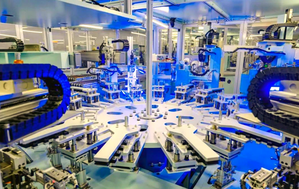
I begin with a comparative overview of battery models, because the choice of model determines which physics can be resolved and which phenomena are averaged out. Electrochemical models are physically transparent and can predict internal concentration and potential distributions. Equivalent circuit models are computationally efficient and are suitable for online state estimation, but they cannot explain dendrite growth or fracture. Thermal-electrochemical-mechanical models can capture safety and degradation, but they require many parameters. Neural network models are data-driven and can handle nonlinear behavior, but they need high-quality data and have limited extrapolation ability. Table 1 summarizes these trade-offs.
| Model family | Core principle | Main advantages | Main limitations | Typical use in a solid state cell |
|---|---|---|---|---|
| Electrochemical model | Reaction and transport equations, such as the pseudo-two-dimensional model | Physical meaning is clear, internal states are resolved, and material design can be guided | High computational cost, many parameters, difficult to scale to modules | Electrode optimization, interfacial kinetics, concentration polarization, and cell-level voltage prediction |
| Equivalent circuit model | Resistors, capacitors, and impedance elements fitted to terminal behavior | Simple, fast, easy parameter identification, suitable for real-time control | Does not reveal internal mechanisms or degradation modes | Battery management, state estimation, and rapid system-level simulation |
| Thermal-electrochemical-mechanical model | Coupled electrochemistry, heat transfer, and solid mechanics | Can evaluate safety, stress, fracture, and thermal runaway | Very high computational demand and complex parameter acquisition | Thermal management, stress analysis, interface failure, and extreme-condition safety |
| Neural network model | Data-driven mapping from inputs to battery states | Handles nonlinearity, can fuse multiple data sources, and is fast after training | Requires large datasets, poor extrapolation, and weak physical interpretability | Life prediction, complex dynamic conditions, and data-rich industrial scenarios |
From my perspective, the most promising route is not to choose one model family exclusively, but to build hybrid frameworks. A solid state cell model can use an equivalent circuit for online estimation, an electrochemical model for internal states, a mechanical model for stress and fracture, and a data-driven correction for unmodeled effects. This hybrid strategy is especially important for the solid state cell because its degradation is often caused by coupled interface and mechanical phenomena that are not captured by a single model class.
Before discussing atomistic methods, I note that the industrialization of the solid state cell is already moving from laboratory cells to pilot and pre-production stages. Several global automotive and battery manufacturers have announced targets in the range of 350 to 500 Wh/kg, with small-batch production and vehicle demonstration expected in the late 2020s. Table 2 summarizes these generic technology routes without identifying specific organizations. The key point is that the solid state cell is no longer a purely academic concept; it is a technology with clear performance targets and a pressing need for predictive models that can shorten development cycles.
| Technology route | Typical energy density target | Expected maturity window | Main modeling challenge |
|---|---|---|---|
| Sulfide-based solid state cell | 400 to 500 Wh/kg | Small batch around 2027, scale-up after 2030 | Moisture sensitivity, lithium metal compatibility, dendrite penetration, and chemo-mechanical fracture |
| Oxide-based solid state cell | 350 to 450 Wh/kg | Pilot production in the late 2020s | High interfacial resistance, sintering-induced defects, and contact loss |
| Polymer and composite solid state cell | 300 to 400 Wh/kg | Early deployment through semi-solid and hybrid designs | Low room-temperature conductivity, mechanical softening, and long-term interface stability |
| Halide and mixed solid electrolyte cell | 400 Wh/kg and above | Emerging, with longer development horizon | Stability window, interphase formation, and scalable synthesis |
I now turn to molecular dynamics and atomistic calculations. These methods are essential for the solid state cell because macroscopic transport and degradation originate from atomic-scale migration barriers, defect energetics, and interfacial reactions. Molecular dynamics tracks atomic trajectories by integrating Newton’s equations of motion. The mean square displacement is a central quantity for ion transport:
$$ \mathrm{MSD}(t) = \left\langle \left| \mathbf{r}(t) – \mathbf{r}(0) \right|^2 \right\rangle $$
The self-diffusion coefficient follows from the long-time limit:
$$ D = \lim_{t \to \infty} \frac{1}{6t} \mathrm{MSD}(t) $$
For many solid electrolytes, the temperature dependence of diffusion and conductivity follows an Arrhenius relationship:
$$ D = D_0 \exp\left( -\frac{E_a}{k_B T} \right) $$
$$ \sigma T = \sigma_0 \exp\left( -\frac{E_a}{k_B T} \right) $$
Here, \(E_a\) is the activation energy, \(k_B\) is the Boltzmann constant, \(T\) is temperature, \(D_0\) is a pre-exponential factor, and \(\sigma_0\) is a conductivity prefactor. Density functional theory and ab initio molecular dynamics can provide these parameters for candidate solid electrolytes. In my view, the most valuable atomistic contributions to the solid state cell are the identification of migration pathways, the quantification of dopant effects, and the prediction of interfacial reaction products.
Table 3 compares several atomistic and mesoscale methods that I use to interpret solid state cell behavior. Each method has a different balance between accuracy and accessible length and time scales.
| Method | Length scale | Time scale | Primary output | Role in solid state cell modeling |
|---|---|---|---|---|
| Density functional theory | Angstrom to nanometers | Picoseconds | Electronic structure, energies, barriers, elastic constants | Interface stability, defect formation, surface electron states, and migration barriers |
| Ab initio molecular dynamics | Nanometers | Picoseconds to nanoseconds | Diffusion coefficients and structural evolution | Ion transport in crystalline and disordered solid electrolytes |
| Classical molecular dynamics | Nanometers to tens of nanometers | Nanoseconds to microseconds | Atomic trajectories, MSD, elastic properties | Grain boundary softening, thermal effects, and interfacial structure |
| Kinetic Monte Carlo | Nanometers to micrometers | Microseconds to seconds | Diffusion and reaction kinetics | Long-time ion transport and phase evolution in solid state cell electrodes |
| Phase-field model | Nanometers to micrometers | Microseconds to seconds | Morphology, phase boundaries, and damage | Dendrite growth, crack propagation, and interphase evolution |
For sulfide solid electrolytes, the argyrodite family is especially important. Its ionic conductivity depends strongly on composition, halogen disorder, and lithium vacancy concentration. Table 4 summarizes representative ionic and electronic conductivities for several argyrodite compositions. These values illustrate why the solid state cell community pays close attention to halogen mixing and sulfur-halogen substitution: small structural changes can alter conductivity by orders of magnitude.
| Composition | Ionic conductivity (mS/cm) | Electronic conductivity (mS/cm) | Modeling implication |
|---|---|---|---|
| Li5.5PS4.5Cl1.5 | 3.9 | 1.4 × 10^-5 | High ionic conductivity but non-negligible electronic conductivity |
| Li5.75PS4.75Cl1.25 | 3.0 | 2.6 × 10^-5 | Chlorine substitution creates lithium vacancies and changes transport |
| Li6PS5Br | 1.9 | 4.4 × 10^-6 | Bromide variant with lower ionic conductivity |
| Li6PS5Cl0.25Br0.75 | 3.4 | 1.1 × 10^-5 | Mixed halide improves conductivity relative to single halide |
| Li6PS5Cl0.5Br0.5 | 3.9 | 1.4 × 10^-5 | Balanced halide mixture gives high ionic conductivity |
| Li6PS5Cl0.75Br0.25 | 3.2 | 3.7 × 10^-6 | Halide ratio affects both transport and stability |
| Li6PS5Cl | 2.4 | 5.1 × 10^-6 | Reference composition for comparison |
The next scale is the key material and interface level. I divide this into positive electrode modeling, negative electrode modeling, and solid electrolyte modeling. In a solid state cell, these three regions cannot be treated independently because the interface between them controls rate capability, capacity retention, and safety.
For the positive electrode, the composite structure contains active material particles, solid electrolyte, conductive additives, and pores. Porous electrode theory remains useful, but it must be extended to include solid-solid contact, mechanical stress, and interfacial resistance. The lithium concentration in an active particle is often described by spherical diffusion:
$$ \frac{\partial c_s}{\partial t} = \frac{1}{r^2} \frac{\partial}{\partial r} \left( r^2 D_s \frac{\partial c_s}{\partial r} \right) $$
The boundary condition at the particle surface is related to the interfacial current density:
$$ -D_s \frac{\partial c_s}{\partial r} \bigg|_{r=R} = \frac{j}{F} $$
The electrochemical reaction rate is commonly written using Butler-Volmer kinetics:
$$ j = i_0 \left[ \exp\left( \frac{\alpha_a F \eta}{RT} \right) – \exp\left( -\frac{\alpha_c F \eta}{RT} \right) \right] $$
In a solid state cell, the overpotential \(\eta\) is influenced not only by concentration and potential, but also by mechanical stress. A simplified chemo-mechanical overpotential correction can be written as:
$$ \eta = \phi_s – \phi_e – U – \frac{\Omega \sigma_n}{F} $$
Here, \(\Omega\) is the partial molar volume, \(\sigma_n\) is the normal stress at the interface, and \(U\) is the open-circuit potential. This coupling explains why external stack pressure can change the apparent kinetics of a solid state cell. I have found that ignoring this term can lead to large errors in predicted voltage and capacity, especially for high-capacity positive materials that undergo significant volume change.
Mechanical deformation in the positive electrode is described by a chemo-elastic constitutive law. The total strain is decomposed into elastic, chemical, and thermal parts:
$$ \varepsilon_{ij} = \varepsilon_{ij}^{el} + \varepsilon_{ij}^{chem} + \varepsilon_{ij}^{th} $$
The chemical strain is often assumed to be proportional to the concentration change:
$$ \varepsilon_{ij}^{chem} = \frac{1}{3} \Omega \Delta c \, \delta_{ij} $$
The stress follows Hooke’s law:
$$ \sigma_{ij} = C_{ijkl} \left( \varepsilon_{kl} – \varepsilon_{kl}^{chem} – \varepsilon_{kl}^{th} \right) $$
For a composite positive electrode, damage and fracture can be modeled using cohesive zones or phase-field damage. The energy release rate \(G\) and fracture toughness \(K_{IC}\) determine whether a crack propagates:
$$ G = \frac{K_I^2}{E’} $$
$$ K_I = Y \sigma \sqrt{\pi a} $$
Here, \(a\) is crack length, \(Y\) is a geometry factor, and \(E’\) is the effective modulus. In the solid state cell, crack propagation is dangerous because it creates fresh surfaces for reaction and can provide pathways for lithium penetration.
Table 5 summarizes the main positive electrode modeling considerations for a solid state cell. I emphasize that the trade-off between ionic conductivity, electronic conductivity, mechanical compliance, and interfacial stability is the core design problem.
| Positive electrode factor | Physical effect | Modeling treatment | Impact on solid state cell |
|---|---|---|---|
| Particle radius | Changes diffusion length and stress magnitude | Spherical diffusion and chemo-mechanical stress | Smaller particles improve rate but increase surface area and interfacial reaction |
| Porosity | Controls ion transport pathways and mechanical accommodation | Effective medium theory and homogenization | Excess porosity reduces energy density; too little porosity increases stress |
| Contact area | Determines interfacial resistance and current distribution | Contact mechanics and impedance boundary conditions | Contact loss causes capacity fade and uneven lithiation |
| Volume change | Generates stress, fracture, and delamination | Chemo-elasticity, plasticity, and cohesive fracture | Can cause capacity loss and impedance rise |
| Solid electrolyte fraction | Provides ionic percolation and mechanical support | Effective conductivity and composite micromechanics | Optimal fraction balances transport and energy density |
For the negative electrode, lithium metal is the most attractive because of its low potential and high theoretical capacity. However, lithium deposition in a solid state cell is unstable. The morphology of lithium deposits can be needle-like, mossy, or tree-like. Table 6 summarizes these morphologies and their consequences.
| Dendrite morphology | Growth characteristics | Main consequence | Modeling approach |
|---|---|---|---|
| Needle-like | Grows in both lateral and vertical directions | Can puncture the solid electrolyte and cause internal short circuit | Phase-field and linear stability analysis |
| Mossy-like | High surface area, small diameter, consumes lithium | Forms dead lithium and increases interfacial resistance | Diffusion-reaction and morphological evolution models |
| Tree-like | Branches in multiple directions | Capacity loss, short circuit, and safety risk | Electrochemical-mechanical phase-field models |
The classical description of electrodeposition stability begins with the current-overpotential relationship. In a solid state cell, the mechanical stress at the interface modifies the electrochemical driving force. A widely used form is:
$$ i = i_0 \left[ \exp\left( \frac{(1-\alpha) F \eta}{RT} \right) – \exp\left( -\frac{\alpha F \eta}{RT} \right) \right] $$
The interfacial overpotential can include stress work:
$$ \eta = \phi_s – \phi_e – U – \frac{\Omega}{F} \sigma_n $$
Linear stability analysis often predicts that a planar interface is unstable when the current density exceeds a critical value. A simplified stability criterion can be written as:
$$ J_{crit} \propto \frac{\sigma_{int} \Omega}{F L} + \frac{G_{int}}{L^2} $$
Here, \(\sigma_{int}\) is the interfacial stress, \(L\) is a characteristic length, and \(G_{int}\) is the interfacial energy. In my assessment, the competition between interfacial energy, stress, and ion transport is the central issue for dendrite suppression in the solid state cell.
Lithium metal also exhibits plastic and viscoplastic deformation. The large-deformation elastic-viscoplastic model is written in terms of the deformation gradient \(\mathbf{F}\) and the Cauchy stress \(\boldsymbol{\sigma}\). The chemical contribution to deformation is included through a swelling term:
$$ \mathbf{F} = \mathbf{F}^{el} \mathbf{F}^{pl} \mathbf{F}^{chem} $$
The chemical deformation gradient for isotropic swelling is:
$$ \mathbf{F}^{chem} = \left( 1 + \frac{\Omega \Delta c}{3} \right) \mathbf{I} $$
This type of model shows that lithium can be compressed and squeezed along the interface, and that plastic flow can either blunt or sharpen a dendrite depending on the local stress state. I consider this one of the most important directions for improving the predictive power of solid state cell models.
Silicon-based negative electrodes are another important case. Silicon undergoes very large volume changes during lithiation and delithiation, often exceeding 300 percent. The chemical strain is large, and plastic deformation and fracture are unavoidable unless the architecture is carefully designed. The large-deformation theory uses the multiplicative decomposition of the deformation gradient and a free energy that depends on both elastic deformation and lithium concentration. A simplified expression for the chemical strain is:
$$ \varepsilon^{chem} = \frac{1}{3} \Omega c \mathbf{I} $$
For a spherical particle, the radial and tangential stresses can be computed by solving the diffusion equation together with mechanical equilibrium:
$$ \nabla \cdot \boldsymbol{\sigma} = 0 $$
Phase-field damage models are often used to predict crack initiation and propagation in silicon particles. The damage variable \(d\) degrades the stiffness:
$$ \sigma_{ij} = (1-d)^2 C_{ijkl} \left( \varepsilon_{kl} – \varepsilon_{kl}^{chem} \right) $$
The evolution of damage is driven by the elastic energy density and a fracture energy threshold. In a solid state cell, silicon particles are embedded in a solid electrolyte matrix, so the particle-matrix interaction, void formation, and contact loss must be included. This is a much more complex problem than in a liquid electrolyte battery, where the liquid can accommodate volume changes more easily.
I now focus on the solid electrolyte itself. Its microstructure includes grains, grain boundaries, pores, cracks, and secondary phases. These features determine effective ionic conductivity, mechanical modulus, and failure mode. The Nernst-Planck equation describes coupled diffusion and migration:
$$ \mathbf{J}_i = -D_i \nabla c_i – \frac{z_i F}{RT} D_i c_i \nabla \phi $$
The conservation equation for each species is:
$$ \frac{\partial c_i}{\partial t} + \nabla \cdot \mathbf{J}_i = 0 $$
In a solid electrolyte with immobilized anions, the ionic current is carried mainly by lithium ions. A common simplification is:
$$ \mathbf{i} = – \sigma_e \nabla \phi_e + \frac{\sigma_e RT}{F} \left( 1 – t_+ \right) \nabla \ln c_e $$
The space charge layer near an interface is described by Poisson’s equation:
$$ \nabla \cdot \left( \varepsilon \nabla \phi \right) = – F \sum_i z_i c_i $$
The Debye length characterizes the thickness of the space charge region:
$$ \lambda_D = \sqrt{ \frac{\varepsilon k_B T}{2 e^2 c_0} } $$
When the space charge layer is significant, the local lithium concentration near the interface can be depleted, which increases interfacial resistance. This effect is more pronounced in a solid state cell than in a liquid electrolyte cell because the solid electrolyte cannot replenish ions by convection.
Interface contact loss is another dominant degradation mode. The interfacial resistance depends on the real contact area:
$$ R_{int} = \frac{\rho_{int}}{A_{contact}} $$
During cycling, volume changes can create voids and reduce \(A_{contact}\). The contact pressure required to maintain contact can be estimated from contact mechanics. A simplified Hertzian contact relation is:
$$ a = \left( \frac{3 F R}{4 E^*} \right)^{1/3} $$
Here, \(a\) is the contact radius, \(F\) is the applied force, \(R\) is the effective radius, and \(E^*\) is the effective modulus. In a solid state cell, stack pressure is therefore not a secondary variable; it directly controls the interfacial area and current distribution.
Crack propagation in the solid electrolyte is driven by stress, including stress from interphase formation, thermal expansion, and lithium insertion. The Griffith criterion gives the critical stress for crack growth:
$$ \sigma_c = \sqrt{ \frac{2 E \gamma_s}{\pi a} } $$
When lithium fills a crack, the pressure inside the crack can be large enough to drive fracture. A simplified expression for the pressure generated by lithium deposition is:
$$ p = \frac{F \eta \rho}{M} $$
Here, \(\rho\) is the density of lithium and \(M\) is its molar mass. If \(p\) exceeds the critical value, the crack can propagate through the solid electrolyte. This mechanism explains why a high-modulus solid electrolyte is not automatically immune to dendrites. Interfacial adhesion, surface defects, and grain boundary softening can dominate over bulk modulus.
Table 7 summarizes the main solid electrolyte degradation mechanisms and the corresponding modeling strategies. I use this table to emphasize that the solid state cell fails through multiple coupled pathways, not through a single transport limitation.
| Degradation mechanism | Physical origin | Modeling strategy | Effect on solid state cell |
|---|---|---|---|
| Space charge depletion | Difference in chemical potential and immobile anions | Poisson-Nernst-Planck equations | High interfacial resistance and reduced rate capability |
| Interphase formation | Reduction or oxidation of the solid electrolyte | Diffusion-reaction and phase-field models | Impedance growth and capacity fade |
| Void formation | Uneven lithium stripping and volume change | Chemo-mechanical contact models | Contact loss and current constriction |
| Crack propagation | Stress from interphase, thermal expansion, or lithium pressure | Cohesive zone and phase-field fracture | Short circuit and mechanical failure |
| Grain boundary softening | Local disorder and weaker atomic bonding | Molecular dynamics and micromechanics | Preferred lithium penetration pathways |
| Surface defects | Scratches, pores, and pre-existing flaws | Fracture mechanics and defect statistics | Early dendrite nucleation |
Mechanical properties of the solid electrolyte are also critical. Elastic modulus, hardness, toughness, and plasticity determine how the solid state cell responds to stack pressure and cycling. For many inorganic solid electrolytes, the Pugh modulus ratio \(G/K\) can be used to estimate brittleness. A high ratio indicates brittleness, while a low ratio indicates ductility. The bulk modulus \(K\), shear modulus \(G\), and Young’s modulus \(E\) are related by:
$$ K = \frac{E}{3(1-2\nu)} $$
$$ G = \frac{E}{2(1+\nu)} $$
Here, \(\nu\) is Poisson’s ratio. In my reading of the literature, the solid state cell community has moved from the idea that “stiffer is better” to a more nuanced view: stable electrodeposition requires a balance between mechanical stiffness, interfacial adhesion, ionic conductivity, and defect tolerance.
At the cell level, the electrochemical performance of a solid state cell is modeled by coupling charge conservation, mass conservation, and reaction kinetics. The charge conservation equation in the solid phase is:
$$ \nabla \cdot \left( \sigma_s \nabla \phi_s \right) = – a j $$
In the electrolyte phase, the ionic current satisfies:
$$ \nabla \cdot \left( \sigma_e \nabla \phi_e \right) = a j $$
The volumetric reaction rate \(a j\) is given by Butler-Volmer kinetics. The lithium concentration in the solid electrolyte evolves according to:
$$ \frac{\partial c_e}{\partial t} = \nabla \cdot \left( D_e \nabla c_e \right) + \frac{a j}{F} $$
For a one-dimensional solid state cell, these equations are solved along the thickness direction. The cell voltage is the difference between the solid-phase potentials at the current collectors minus the interfacial overpotentials and ohmic drops:
$$ V = \phi_s^{pos} – \phi_s^{neg} – \eta_{pos} – \eta_{neg} – I R_{cell} $$
I note that the traditional pseudo-two-dimensional model cannot be directly applied to a solid state cell because the electrolyte is not a binary liquid with convection-free transport and because mechanical contact is not perfect. However, the pseudo-two-dimensional framework can be extended by adding a contact resistance, a concentration-dependent diffusion coefficient, and a stress-dependent reaction rate.
Table 8 lists the key parameters that I would include in a cell-level solid state cell model. The table also indicates whether each parameter is typically obtained from experiment, atomistic simulation, or calibration.
| Parameter | Symbol | Typical source | Influence on solid state cell |
|---|---|---|---|
| Solid diffusion coefficient | \(D_s\) | Experiment or atomistic calculation | Rate capability and concentration polarization |
| Electrolyte ionic conductivity | \(\sigma_e\) | Impedance spectroscopy | Ohmic loss and current distribution |
| Exchange current density | \(i_0\) | Kinetic experiments | Interfacial reaction rate |
| Contact resistance | \(R_{int}\) | Impedance or contact mechanics | Voltage loss and heat generation |
| Partial molar volume | \(\Omega\) | Crystallography or experiment | Chemo-mechanical stress |
| Elastic modulus | \(E\) | Nanoindentation or simulation | Stress, fracture, and contact stability |
| Fracture energy | \(G_c\) | Fracture tests or simulation | Crack initiation and propagation |
| Thermal conductivity | \(k\) | Thermal experiments | Temperature distribution and thermal runaway |
Mechanical modeling of the solid state cell at the cell level requires solving the equilibrium equation:
$$ \nabla \cdot \boldsymbol{\sigma} = 0 $$
The constitutive relation includes chemical and thermal strains:
$$ \boldsymbol{\sigma} = \mathbf{C} : \left( \boldsymbol{\varepsilon} – \boldsymbol{\varepsilon}^{chem} – \boldsymbol{\varepsilon}^{th} \right) $$
The thermal strain is:
$$ \boldsymbol{\varepsilon}^{th} = \alpha \Delta T \mathbf{I} $$
The chemical strain for lithium insertion is:
$$ \boldsymbol{\varepsilon}^{chem} = \frac{1}{3} \Omega \Delta c \mathbf{I} $$
These equations are solved together with the electrochemical equations because the stress affects the reaction kinetics and transport. In a solid state cell, the mechanical problem is not optional; it is a core part of the electrochemical performance. I have observed that models that neglect stress can overpredict capacity and underestimate degradation, especially at high rates and high stack pressures.
Multiphysics coupling is the natural framework for the solid state cell. The main fields are electrochemical potential, lithium concentration, temperature, stress, and damage. The heat generation includes ohmic, reaction, and reversible terms:
$$ \rho C_p \frac{\partial T}{\partial t} = \nabla \cdot \left( k \nabla T \right) + Q_{ohm} + Q_{rxn} + Q_{rev} $$
The ohmic heat is:
$$ Q_{ohm} = \sigma_s |\nabla \phi_s|^2 + \sigma_e |\nabla \phi_e|^2 $$
The reaction heat is:
$$ Q_{rxn} = a j \eta $$
The reversible heat is:
$$ Q_{rev} = a j T \frac{\partial U}{\partial T} $$
These heat sources change the temperature, which changes transport, kinetics, and mechanical properties. The temperature also generates thermal stress, which can initiate cracks. This feedback loop is central to the safety of the solid state cell.
Table 9 summarizes the main multiphysics coupling terms that I include in a solid state cell model. The table is organized by the primary field and the secondary field that it influences.
| Primary field | Secondary field | Coupling term or effect | Modeling significance |
|---|---|---|---|
| Electrochemical potential | Concentration | Migration and reaction | Current distribution and overpotential |
| Concentration | Stress | Chemical strain and diffusion-induced stress | Fracture and contact loss |
| Stress | Reaction kinetics | Stress-dependent overpotential | Modified exchange current and deposition stability |
| Temperature | Transport and kinetics | Arrhenius dependence | Rate capability and thermal runaway |
| Temperature | Stress | Thermal expansion mismatch | Crack initiation and delamination |
| Damage | Transport and kinetics | Degraded stiffness and conductivity | Accelerated degradation and failure |
Several studies have shown that design parameters have a strong effect on solid state cell performance. Increasing positive electrode thickness can increase capacity, but it also increases ionic and electronic transport lengths. Reducing electrolyte thickness can reduce ohmic resistance, but it increases the risk of short circuit by dendrites. Increasing stack pressure can improve contact and reduce voids, but it can also drive crack propagation. These trade-offs are summarized in Table 10.
| Design parameter | Potential benefit | Potential penalty | Best modeling approach |
|---|---|---|---|
| Positive electrode thickness | Higher areal capacity | Higher transport resistance and stress | 1D electrochemical model with stress coupling |
| Electrolyte thickness | Lower ohmic resistance | Higher dendrite short-circuit risk | Electrochemical-mechanical stability model |
| Particle size | Shorter diffusion length | More interfaces and side reactions | Microscale diffusion and phase-field model |
| Stack pressure | Better contact and lower void volume | Crack propagation and creep | Contact mechanics and fracture model |
| Solid electrolyte modulus | Mechanical support and dendrite suppression | Poor contact and fracture | Chemo-mechanical coupling model |
| Operating temperature | Higher conductivity and kinetics | Accelerated degradation and thermal stress | Thermal-electrochemical-mechanical model |
In my view, the most important future directions for solid state cell modeling are the following. First, the positive electrode requires detailed continuum modeling of three-dimensional composite microstructures with damage and fracture. Second, the lithium metal anode requires a fully coupled electrochemical-mechanical model that includes plasticity, viscoplasticity, and interfacial adhesion. Third, the solid electrolyte requires models for interphase formation, void growth, and crack propagation at grain boundaries and defects. Fourth, data-driven methods should be integrated with physical models to accelerate materials screening and parameter identification. Fifth, experimental validation must be strengthened, especially for buried interfaces and operando conditions.
For the positive electrode, I recommend that future models include anisotropic material behavior, realistic particle size distributions, and non-ideal contact geometry. The representative volume element should be large enough to capture percolation and stress heterogeneity, but small enough to be computationally feasible. Boundary conditions should be chosen carefully to avoid artificial stress concentrations. The constitutive laws should include plasticity and damage so that capacity fade can be linked to mechanical degradation.
For the negative electrode, I recommend that future models treat lithium metal as a deformable, viscoplastic material rather than a rigid boundary. The interaction between lithium flow and interface morphology is essential. The model should also include the effect of stack pressure on creep and contact area. In addition, the nucleation and growth of voids during stripping should be modeled, because void formation is a major source of impedance rise in the solid state cell.
For the solid electrolyte, I recommend that future models capture the formation and evolution of interphases. The reaction between the solid electrolyte and the electrode can produce ionically conductive but electronically insulating phases, or mixed conducting phases that continue to grow. The model should include volume expansion, stress generation, and fracture. It should also include the effect of grain boundaries, pores, and surface defects. Machine learning can accelerate the screening of solid electrolytes, but the training data should be generated from physically consistent models and validated against experiments.
At the cell level, I recommend that future models use a modular multiphysics architecture. Each physics module should be validated separately before coupling. The coupling should be performed at the appropriate time scale: electrochemical and transport equations may use a different time step from mechanical equilibrium, and thermal equations may use a different time step from diffusion. Sensitivity analysis should be used to identify the parameters that dominate performance and degradation. Uncertainty quantification should be included because many solid state cell parameters are difficult to measure.
Table 11 summarizes the research priorities that I consider most urgent for the solid state cell. These priorities are not independent; they should be addressed together in a multiscale framework.
| Priority area | Key question | Recommended method | Expected impact |
|---|---|---|---|
| Composite positive electrode | How do microstructure, contact, and fracture control capacity and rate? | 3D continuum modeling with damage and phase-field fracture | Improved electrode design and higher utilization |
| Lithium metal anode | How do plasticity and interfacial stress determine dendrite growth? | Large-deformation electrochemical-mechanical model | Safer and more stable lithium metal solid state cell |
| Solid electrolyte interphase | How do reaction, diffusion, and stress control interphase growth? | Diffusion-reaction and phase-field model | Lower interfacial resistance and longer cycle life |
| Void and contact loss | How do voids form and evolve under stack pressure? | Contact mechanics and moving boundary model | Reduced impedance rise and capacity fade |
| Data-driven materials screening | Which solid electrolytes suppress dendrites and resist fracture? | Machine learning with physical descriptors | Faster discovery of new solid electrolytes |
| Multiphysics validation | How can buried interfaces be measured under operation? | Operando characterization and model inversion | Higher predictive accuracy and design confidence |
I conclude that modeling and simulation are indispensable for the development of the solid state cell. Atomistic calculations provide the fundamental parameters and mechanisms. Microscale models reveal how particles, grains, pores, and cracks interact. Continuum models predict cell-level voltage, capacity, impedance, and thermal behavior. Multiphysics coupling connects these scales and captures the feedback loops that control degradation. The solid state cell is not simply a liquid electrolyte battery with a solid electrolyte; it is a new class of chemo-mechanical system. Its performance and safety depend on the simultaneous optimization of transport, mechanics, interfaces, and manufacturing.
From my perspective, the most promising path forward is a hierarchical, physics-based, data-informed modeling framework. Such a framework should be able to answer questions such as: What stack pressure is optimal for a given solid electrolyte and electrode geometry? How does particle size distribution affect the onset of fracture? What interface chemistry minimizes interphase growth while maintaining ionic contact? How does the solid state cell behave under fast charging, low temperature, and mechanical abuse? By answering these questions, the modeling community can reduce experimental trial-and-error and accelerate the industrialization of the solid state cell. I believe that the continued integration of atomistic simulation, continuum mechanics, electrochemical modeling, machine learning, and operando experiments will make the solid state cell a practical and reliable next-generation energy storage technology.