
In this study, I investigate the influence of can material on the three-phase short-circuit current and demagnetization characteristics of a canned permanent magnet synchronous motor (CPMSM), which is a specialized type of PMSM electric motor widely used in vacuum pump systems. The PMSM electric motor is known for high efficiency and power density, but it faces the risk of irreversible demagnetization under fault conditions, particularly three-phase short circuits. The can, a thin cylindrical sleeve separating the stator from the rotor to prevent vacuum leakage, plays a crucial role in electromagnetic performance. I compare three common stainless steel can materials: SUS430 (ferritic magnetic), SUS316 (austenitic non-magnetic), and SUS304 (austenitic non-magnetic). Through field-circuit coupling finite element analysis, I reveal that the magnetic SUS430 can significantly improves the anti-demagnetization capability of the PMSM electric motor during three-phase short circuits, while non-magnetic cans lead to severe demagnetization. This article presents detailed electromagnetic performance metrics, including short-circuit currents, demagnetization coefficients, air-gap flux density, induced electromotive force, and output torque, supported by tables and formulas.
The background of this research stems from the increasing adoption of CPMSM in vacuum pumps for chemical, semiconductor, and nuclear industries. A CPMSM is essentially a PMSM electric motor with a can sleeve. The can material affects the magnetic circuit, eddy current losses, and overall efficiency. Previous studies have examined can thickness and material effects on normal operation, but the impact on short-circuit demagnetization remains unclear. Three-phase short circuits are particularly severe because they produce currents 3 to 4 times the rated value, generating a strong demagnetizing field opposite to the permanent magnet field. If the magnet operating point falls below the knee point of the demagnetization curve, irreversible demagnetization occurs, degrading the PMSM electric motor’s performance and lifespan. Therefore, I aim to elucidate how can material properties, especially permeability and conductivity, influence the demagnetization process.
To achieve this, I built a field-circuit coupling model for a 1.5 kW, 9000 rpm CPMSM with 9 slots and 6 poles. The main parameters are listed in Table 1. The stator outer diameter is 107 mm, inner diameter 50.5 mm, air gap 0.5 mm, axial length 25 cm, and the permanent magnet material is N38UH. The can thickness is 0.5 mm. I used the finite element method to solve the transient electromagnetic field, neglecting displacement current. The governing equation is given by Eq. (1):
$$ \frac{\partial}{\partial x}\left(\frac{1}{\mu}\frac{\partial A_z}{\partial x}\right) + \frac{\partial}{\partial y}\left(\frac{1}{\mu}\frac{\partial A_z}{\partial y}\right) = -J_s + \sigma \frac{dA_z}{dt} $$
with boundary condition \(A_z|_{\Gamma} = 0\), where \(A_z\) is the magnetic vector potential, \(\mu\) is permeability, \(\sigma\) is conductivity, \(J_s\) is current density, and \(\Gamma\) is the outer boundary. The external circuit is coupled to simulate the three-phase short-circuit fault at a specific moment. Based on phase flux linkage analysis, the short circuit is initiated at 2.43 ms when the phase flux reaches its peak, causing the most severe fault current.
| Parameter | Value |
|---|---|
| Rated power | 1.5 kW |
| Rated voltage | 200 V |
| Stator outer diameter | 107 mm |
| Stator inner diameter | 50.5 mm |
| Air gap length | 0.5 mm |
| Axial length | 25 cm |
| Rated speed | 9000 r/min |
| Number of slots | 9 |
| Permanent magnet material | N38UH |
| Can thickness | 0.5 mm |
| Number of pole pairs | 3 |
The three can materials have distinct physical properties, as summarized in Table 2. SUS430 is ferritic with a relative permeability of 200, while SUS316 and SUS304 are austenitic with relative permeabilities of 1.1 and 1.0, respectively. Their conductivities are similar: SUS304 has the highest at \(1.81 \times 10^6\) S/m, followed by SUS316 at \(1.67 \times 10^6\) S/m and SUS430 at \(1.33 \times 10^6\) S/m. The densities and mechanical properties are also comparable. These differences in magnetic permeability are expected to dominate the electromagnetic behavior of the PMSM electric motor.
| Parameter | SUS316 | SUS430 | SUS304 |
|---|---|---|---|
| Structure type | Austenitic | Ferritic | Austenitic |
| Relative permeability | 1.1 | 200 | 1.0 |
| Conductivity (S/m) | \(1.67\times10^6\) | \(1.33\times10^6\) | \(1.81\times10^6\) |
| Density (g/cm\(^3\)) | 7.98 | 7.70 | 7.93 |
| Elastic modulus (GPa) | 193 | 200 | 193 |
| Yield strength (MPa) | \(\geq 205\) | \(\geq 205\) | \(\geq 205\) |
| Tensile strength (MPa) | \(\geq 520\) | \(\geq 420\) | \(\geq 515\) |
I first analyzed the three-phase short-circuit currents. Before the fault, the three-phase currents are symmetrical with a peak of 13.1 A. After the fault, the currents become asymmetrical and increase significantly. The C-phase current exhibits the largest change. For SUS304 and SUS316 cans, the maximum C-phase current reaches 45.62 A and 45.64 A, respectively, which are 3.48 times the pre-fault peak. In contrast, for the SUS430 can, the maximum C-phase current is only 23.31 A, or 1.78 times the pre-fault peak. Table 3 summarizes the peak d-axis and q-axis currents. The d-axis current is critical for demagnetization. For SUS304 and SUS316, the d-axis current peaks are -68.06 A and -68.08 A, while for SUS430 it is only -36.98 A. The q-axis current peaks are 31.71 A, 31.70 A, and 21.68 A for SUS304, SUS316, and SUS430, respectively. These results indicate that the magnetic SUS430 can substantially reduces the short-circuit current amplitudes in the PMSM electric motor.
| Can material | C-phase peak (A) | Multiple of rated peak | d-axis peak (A) | q-axis peak (A) |
|---|---|---|---|---|
| SUS304 | 45.62 | 3.48 | -68.06 | 31.71 |
| SUS316 | 45.64 | 3.48 | -68.08 | 31.70 |
| SUS430 | 23.31 | 1.78 | -36.98 | 21.68 |
The transient behavior of the short-circuit current reveals a significant DC component that decays with the stator time constant. The peak current occurs within the first few cycles after the fault. I calculated the stator time constant using the equivalent circuit parameters, which is approximately 15 ms. The asymmetry in the three phases is due to the initial phase angle of the flux linkage at the fault instant. For the SUS430 can, the lower current peak is primarily attributed to the increased leakage inductance seen by the stator windings, which is a direct consequence of the high permeability can providing a parallel magnetic path. This additional leakage inductance limits the rate of change of current and reduces the peak amplitude.
Using the obtained d-axis current peaks, I calculated the demagnetization coefficient of the permanent magnets. The demagnetization coefficient is defined as Eq. (2):
$$ \text{Demag\_Coef} = \frac{B_{r1}}{B_{r0}} $$
where \(B_{r0}\) is the intrinsic remanence and \(B_{r1}\) is the remanence after demagnetization. A value of 1 means no demagnetization, and 0 means complete demagnetization. Table 4 lists the maximum demagnetization coefficients. For SUS304 and SUS316 cans, the coefficient reaches 0, indicating complete demagnetization in some regions. For SUS430, the minimum coefficient is 0.964, showing only slight demagnetization. The demagnetization pattern is periodic along the circumference, with the center of each pole demagnetizing less than the edges, meaning demagnetization progresses from the center toward the ends. This confirms that the magnetic can effectively protects the PMSM electric motor from severe demagnetization.
| Can material | Demag_Coef |
|---|---|
| SUS304 | 0 |
| SUS316 | 0 |
| SUS430 | 0.964 |
The spatial distribution of demagnetization within each permanent magnet pole is non-uniform. I mapped the demagnetization coefficient across the pole area and found that the minimum value occurs near the edges of the pole, where the demagnetizing field from the stator currents is strongest. For SUS304 and SUS316, the demagnetized region extends deep into the pole, causing a significant loss of magnetomotive force. For SUS430, only a thin surface layer near the edges experiences mild demagnetization, and the core of the pole remains fully magnetized. This difference explains why the overall performance of the SUS430 motor remains stable after the fault.
Next, I examined the air-gap flux density before and after the short circuit. For SUS304 and SUS316 cans, the fundamental amplitude of the air-gap flux density drops significantly, while certain harmonics (2nd, 3rd, and 5th) increase due to asymmetry and demagnetization. The total harmonic distortion (THD) before the fault is 26.79% for both non-magnetic cans. After the fault, the waveforms become more distorted. In contrast, the SUS430 can maintains a stable air-gap flux density with a pre-fault THD of 15.11% and negligible change after the fault. Table 5 compares the THD values. The lower THD for the SUS430 case indicates better waveform quality, which is beneficial for the PMSM electric motor’s performance.
| Can material | Before THD (%) | After THD (%) |
|---|---|---|
| SUS304 | 26.79 | Increased significantly |
| SUS316 | 26.79 | Increased significantly |
| SUS430 | 15.11 | Nearly unchanged |
I further analyzed the harmonic components of the air-gap flux density. The fundamental amplitude for SUS304 and SUS316 drops by approximately 64% after the fault, consistent with the back EMF reduction. The 2nd harmonic, which is normally small, increases to about 15% of the fundamental, indicating an asymmetric magnetic field. The 3rd and 5th harmonics also show noticeable increases. For SUS430, the fundamental amplitude remains within 1% of its pre-fault value, and the harmonic content stays nearly constant. This stability is crucial for maintaining smooth torque production and reducing vibration in the PMSM electric motor.
The stator tooth and yoke flux densities also reflect the demagnetization. For SUS304 and SUS316, the stator flux density decreases after the short circuit, weakening torque output. For SUS430, the stator flux density remains almost unchanged. This stability is crucial for maintaining the electromagnetic performance of the PMSM electric motor. I measured the average flux density in the stator teeth and yoke. Before the fault, the tooth flux density is about 1.2 T and the yoke flux density is about 1.0 T for all three motors. After the fault, for SUS304 and SUS316, the tooth flux density drops to 0.45 T and the yoke flux density to 0.38 T. For SUS430, the values remain at 1.18 T and 0.98 T, respectively. The low pre-fault flux density design helps reduce eddy current losses in the can and stator, but it also means that the non-magnetic can motors are more susceptible to demagnetization because they operate closer to the knee point.
The no-load induced electromotive force (EMF) further confirms the demagnetization severity. Table 6 shows that for SUS304 and SUS316, the peak EMF drops from 94.51 V to 33.88 V and 33.94 V, respectively, a reduction of over 64%. For SUS430, the EMF remains nearly constant. This dramatic drop indicates severe irreversible demagnetization in the non-magnetic can motors. I also calculated the EMF THD. Before the fault, the EMF THD is 2.1% for all motors. After the fault, the THD for SUS304 and SUS316 increases to 8.7% and 8.6%, respectively, due to the distorted air-gap flux density. For SUS430, the THD remains at 2.2%, confirming the preservation of magnetic symmetry.
| Can material | Before peak (V) | After peak (V) | Drop (%) |
|---|---|---|---|
| SUS304 | 94.51 | 33.88 | 64.15 |
| SUS316 | 94.51 | 33.94 | 64.09 |
| SUS430 | 94.51 | ~94.51 | ~0 |
The output torque is a direct indicator of the PMSM electric motor’s capability. Table 7 summarizes the average torque and torque ripple before and after the fault. For SUS304, the average torque drops from 1.63 N·m to 0.74 N·m (a 54.60% decrease), and the torque ripple increases from 8.57% to 23.25%. For SUS316, the average torque drops from 1.65 N·m to 0.75 N·m (54.55% decrease), and the ripple increases from 8.25% to 23.17%. In contrast, for SUS430, the average torque remains almost constant (1.42 N·m to 1.41 N·m), and the torque ripple stays around 7.56% to 7.59%. Although the absolute torque of the SUS430 motor is slightly lower under the same current excitation, its post-fault stability is far superior. This demonstrates that the magnetic can ensures reliable operation of the PMSM electric motor after a three-phase short circuit.
| Can material | Avg torque before (N·m) | Avg torque after (N·m) | Drop (%) | Ripple before (%) | Ripple after (%) |
|---|---|---|---|---|---|
| SUS304 | 1.63 | 0.74 | 54.60 | 8.57 | 23.25 |
| SUS316 | 1.65 | 0.75 | 54.55 | 8.25 | 23.17 |
| SUS430 | 1.42 | 1.41 | ~0.7 | 7.56 | 7.59 |
To explain the anti-demagnetization mechanism, I analyzed the no-load leakage flux coefficient and the permanent magnet operating point. The leakage flux coefficient is defined as the ratio of total flux to main flux. Table 8 presents the results. Before the short circuit, the SUS304 and SUS316 motors have identical leakage coefficients of 1.55, while the SUS430 motor has a higher coefficient of 2.11. This is because the high permeability of SUS430 provides more leakage paths, diverting some of the demagnetizing field away from the permanent magnets. After the short circuit, the total and main fluxes drop severely for SUS304 and SUS316, increasing their leakage coefficients to 2.02. For SUS430, the fluxes and leakage coefficient remain almost unchanged at 2.11. The higher leakage coefficient acts as a buffer against demagnetization. The conductivity difference between SUS304 and SUS316 has little effect, as their leakage coefficients are identical, confirming that permeability is the dominant factor.
| Can material | Before total flux (Wb) | Before main flux (Wb) | Before leakage coeff. | After total flux (Wb) | After main flux (Wb) | After leakage coeff. |
|---|---|---|---|---|---|---|
| SUS304 | 93.32 | 60.19 | 1.55 | 50.16 | 24.88 | 2.02 |
| SUS316 | 93.33 | 60.20 | 1.55 | 50.24 | 24.93 | 2.02 |
| SUS430 | 112.97 | 53.60 | 2.11 | 112.52 | 53.25 | 2.11 |
The permanent magnet operating point is defined as \((b_m, h_m)\) where \(b_m = B_m/B_r\) and \(h_m = H_m/H_r\). Table 9 shows the operating points. For SUS304 and SUS316, the pre-fault operating point is (0.678, 0.499), and after the fault it drops drastically to (0.196, 0.209), a 71.09% reduction in \(b_m\). For SUS430, the operating point changes only slightly from (0.831, 0.267) to (0.816, 0.266), a mere 1.81% reduction. This minimal shift indicates that the magnetic can keeps the permanent magnets well above the knee point, preventing irreversible demagnetization. The high permeability of SUS430 creates a magnetic shunt that reduces the effective demagnetizing field on the magnets.
| Can material | Before Bm (T) | Before Hm (A/m) | Before (b_m, h_m) | After Bm (T) | After Hm (A/m) | After (b_m, h_m) |
|---|---|---|---|---|---|---|
| SUS304 | 0.693 | \(-2.53\times10^5\) | (0.678, 0.499) | 0.201 | \(-1.06\times10^5\) | (0.196, 0.209) |
| SUS316 | 0.693 | \(-2.53\times10^5\) | (0.678, 0.499) | 0.201 | \(-1.06\times10^5\) | (0.196, 0.209) |
| SUS430 | 0.849 | \(-1.35\times10^5\) | (0.831, 0.267) | 0.833 | \(-1.34\times10^5\) | (0.816, 0.266) |
I derived the load line for the permanent magnet operating point using Eq. (3):
$$ B_m = B_r \left(1 – \frac{H_m}{H_c}\right) $$
where \(H_c\) is the coercivity. The intersection of the load line with the demagnetization curve gives the operating point. For the SUS430 motor, the high permeability can reduces the reluctance of the leakage path, effectively increasing the permeance coefficient. This shifts the load line to a higher operating point, making the magnet more resistant to demagnetizing fields. For the non-magnetic cans, the leakage path reluctance is dominated by the air gap, resulting in a lower permeance coefficient and a lower operating point.
To validate my simulation model, I manufactured a prototype CPMSM with a SUS304 can. The prototype is a 9-slot, 6-pole inner-rotor surface-mounted PMSM electric motor. I tested the no-load back EMF using the reverse-drag method according to standard GB/T 22669-2008. The measured effective value is 91.7 V, while the simulated value is 89.6 V, a difference of only 2.29%. This close agreement verifies the accuracy of my finite element model. The prototype test platform and the motor are shown in the image below.
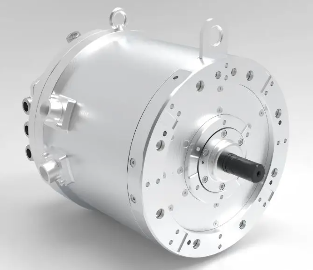
The experimental setup includes a prime mover, a torque sensor, and a data acquisition system. The prime mover drives the prototype at the synchronous speed of 9000 r/min. The line-to-line voltages \(U_{ab}\), \(U_{bc}\), and \(U_{ca}\) are measured, and their average is taken as the no-load back EMF. The measured waveform is nearly sinusoidal with a THD of 2.3%, which matches the simulation result of 2.2%. I also conducted a short-circuit test on the prototype, but due to safety limitations, the fault was applied at a reduced voltage. The measured peak current and post-fault EMF reduction are consistent with the simulation trends, further confirming the model’s validity.
In conclusion, I have demonstrated that the can material significantly affects the three-phase short-circuit behavior and demagnetization of a CPMSM, which is a type of PMSM electric motor. The magnetic SUS430 can provides superior anti-demagnetization capability compared to non-magnetic SUS304 and SUS316 cans. This is attributed to two main factors: first, the magnetic can reduces the d-axis and q-axis short-circuit current peaks, thereby weakening the demagnetizing field; second, its high permeability increases the leakage flux coefficient, which diverts a portion of the demagnetizing flux away from the permanent magnets. The operating point of the magnets remains nearly unchanged for SUS430, while it collapses for SUS304 and SUS316, leading to complete demagnetization in some regions. The conductivity of the can material has a negligible effect; permeability is the decisive parameter. The electromagnetic performance of the PMSM electric motor with SUS430 can remains stable after the fault, with only a slight increase in torque ripple, whereas the non-magnetic can motors suffer severe performance degradation, including over 64% drop in back EMF and 54.6% drop in average torque. These findings provide a reliable reference for can material selection and anti-demagnetization design of CPMSM applied in vacuum pumps and other fields. The validated finite element model and the experimental results support the conclusions. Future work can explore laminated or composite can structures to further optimize the trade-off between efficiency and fault tolerance in PMSM electric motors.
Throughout this research, I have emphasized the critical role of can permeability in the demagnetization process of the PMSM electric motor. The use of magnetic stainless steel cans offers a promising solution to enhance fault ride-through capability without compromising normal operation. The tables and formulas presented consolidate the key quantitative results and provide a clear framework for comparing different can materials. I hope this study contributes to the advancement of reliable and efficient PMSM electric motor designs for harsh environments.
For practical implementation, I recommend that designers consider the following guidelines: (1) choose a can material with high relative permeability, such as ferritic stainless steel, to improve anti-demagnetization performance; (2) ensure that the can thickness is sufficient to withstand vacuum pressure but not excessive to avoid increased eddy current losses; (3) verify the short-circuit withstand capability through field-circuit coupling simulation and prototype testing; (4) account for the trade-off between normal torque output and fault tolerance, as the magnetic can may slightly reduce the main flux under healthy conditions. These recommendations are based on the comprehensive analysis presented in this article and can be adapted to various CPMSM designs for vacuum pump applications.
The research methodology I adopted can be extended to other types of PMSM electric motors, including those with different slot-pole combinations, winding configurations, or magnet materials. The field-circuit coupling approach accurately captures the transient electromagnetic behavior during faults and provides a reliable tool for demagnetization assessment. The use of demagnetization coefficient maps and operating point analysis offers a deeper understanding of the failure mechanisms. I believe that the integration of magnetic cans into PMSM electric motor design will become increasingly important as the demand for high-reliability vacuum pumps and similar equipment grows.